


Washer-Extractors
Pocket Hardmount
2-Speed and 3-Speed
UW35P2
UW35P3
UW60P2
UW60P3
MC010J
Para bajar una copia de estas instrucciones en español, visite www.comlaundry.com.
Keep These Instructions for Future Reference.
(If this machine changes ownership, this manual must accompany machine.)
|
|
|
www.comlaundry.com |
Part No. F232090R3 |
|
|
|
||
|
|
|
February 2007 |
Operation/Programming
Table of
Contents
Safety Information.............................................................................. |
3 |
Explanation of Safety Messages........................................................... |
3 |
Important Safety Instructions ............................................................... |
3 |
Safety Decals ........................................................................................ |
5 |
Key To Symbols ................................................................................... |
6 |
Operator Safety..................................................................................... |
7 |
Safe Operating Environment ................................................................ |
7 |
Environmental Conditions ............................................................... |
7 |
Machine Location ............................................................................ |
8 |
Input and Output Services................................................................ |
8 |
Misuse................................................................................................... |
9 |
Operation............................................................................................. |
10 |
Delivery Inspection............................................................................... |
10 |
Customer Service.................................................................................. |
10 |
Serial Plate Location............................................................................. |
10 |
Machine Familiarization Guide ............................................................ |
12 |
Theory Of Operation............................................................................. |
12 |
Emergency Stop Button........................................................................ |
13 |
WE-6 Microcomputer........................................................................... |
14 |
LED Display ......................................................................................... |
14 |
Operational Keypad .............................................................................. |
17 |
Start-up ................................................................................................. |
18 |
Opening Door ....................................................................................... |
19 |
Loading ................................................................................................. |
19 |
Supply Dispenser .................................................................................. |
19 |
Cycle Selection ..................................................................................... |
19 |
Cycle Execution.................................................................................... |
20 |
Test Cycle ............................................................................................. |
20 |
Stop Routine ......................................................................................... |
21 |
Balance Switch Detection..................................................................... |
21 |
Temperature Display ............................................................................ |
21 |
Error Recovery Routine........................................................................ |
22 |
Motor Thermal Overload Indicator ...................................................... |
22 |
Manual Mode Control Feature.............................................................. |
23 |
Programming ...................................................................................... |
24 |
Programming Keypad........................................................................... |
24 |
Programming Tutorial .......................................................................... |
26 |
Programming Hints............................................................................... |
29 |
System Programming............................................................................ |
30 |
Prompting the WE-6 ........................................................................ |
30 |
Cycle Programming .............................................................................. |
31 |
Displaying a Cycle in Memory ........................................................ |
31 |
Displaying Individual Cycle Usage ................................................. |
31 |
Editing a Cycle................................................................................. |
32 |
Erasing a Cycle in Memory ............................................................. |
33 |
© Copyright 2007, Alliance Laundry Systems LLC
All rights reserved. No part of the contents of this book may be reproduced or transmitted in any form or by any means without the expressed written consent of the publisher.
F232090 |
© Copyright, Alliance Laundry Systems LLC – DO NOT COPY or TRANSMIT |
1 |
Step Programming ................................................................................ |
33 |
Programming a Fill without Spray................................................... |
33 |
Programming a Fill Temperature..................................................... |
33 |
Programming a Supply Step ............................................................ |
35 |
Programming Heat ........................................................................... |
36 |
Programming a Wash Step............................................................... |
36 |
Programming a Wash 5 Thermal Cool-down .................................. |
37 |
Programming No Reversing ............................................................ |
37 |
Programming a Soak Step................................................................ |
38 |
Programming a Drain Step............................................................... |
38 |
Programming a Flush Step............................................................... |
38 |
Programming a Spin Step ................................................................ |
39 |
Programming a Rinse Step............................................................... |
39 |
Programming an Auxiliary Step ...................................................... |
39 |
Simulator Operation and Program Transfer ......................................... |
40 |
Simulator Operation......................................................................... |
40 |
Transferring All Cycles from Computer to Simulator..................... |
41 |
Transferring One Cycle from Computer to Simulator..................... |
41 |
Transferring All Cycles from Simulator to Computer..................... |
42 |
Transferring One Cycle from Simulator to Computer..................... |
42 |
Preprogrammed Cycles......................................................................... |
43 |
Cycle Categories .............................................................................. |
43 |
Standard Supply Legend .................................................................. |
44 |
Standard Cycle Charts...................................................................... |
44 |
2 |
© Copyright, Alliance Laundry Systems LLC – DO NOT COPY or TRANSMIT |
F232090 |

Safety Information
Explanation of Safety Messages
Precautionary statements (“DANGER,” “WARNING,” and “CAUTION”), followed by specific instructions, are found in this manual and on machine decals. These precautions are intended for the personal safety of the operator, user, servicer, and those maintaining the machine.
DANGER
DANGER indicates the presence of a hazard that will cause severe personal injury, death, or substantial property damage if the danger is ignored.
WARNING
WARNING indicates the presence of a hazard that can cause severe personal injury, death, or substantial property damage if the warning is ignored.
CAUTION
CAUTION indicates the presence of a hazard that will or can cause minor personal injury or property damage if the caution is ignored.
Additional precautionary statements (“IMPORTANT” and “NOTE”) are followed by specific instructions.
IMPORTANT: The word “IMPORTANT” is used to inform the reader of specific procedures where minor machine damage will occur if the procedure is not followed.
NOTE: The word “NOTE” is used to communicate installation, operation, maintenance or servicing information that is important but not hazard related.
Important Safety Instructions
WARNING
To reduce the risk of fire, electric shock, serious injury or death to persons when using your washer, follow these basic precautions:
W023
1.Read all instructions before using the washer.
2.Refer to the GROUNDING INSTRUCTIONS in the INSTALLATION manual for the proper grounding of the washer.
3.Do not wash textiles that have been previously cleaned in, washed in, soaked in, or spotted with gasoline, kerosene, waxes, cooking oils, drycleaning solvents, or other flammable or explosive substances as they give off vapors that could ignite or explode.
4.Do not add gasoline, dry-cleaning solvents, or other flammable or explosive substances to the wash water. These substances give off vapors that could ignite or explode.
5.Under certain conditions, hydrogen gas may be produced in a hot water system that has not been used for two weeks or more. HYDROGEN GAS IS EXPLOSIVE. If the hot water system has not been used for such a period, before using a washing machine or combination washer-dryer, turn on all hot water faucets and let the water flow from each for several minutes. This will release any accumulated hydrogen gas. The gas is flammable, do not smoke or use an open flame during this time.
6.Do not allow children to play on or in the washer. Close supervision of children is necessary when the washer is used near children. This is a safety rule for all appliances.
7.Before the washer is removed from service or discarded, remove the door to the washing compartment.
8.Do not reach into the washer if the wash drum is moving.
F232090 |
© Copyright, Alliance Laundry Systems LLC – DO NOT COPY or TRANSMIT |
3 |
Safety Information
9.Do not install or store the washer where it will be exposed to water and/or weather.
10.Do not tamper with the controls.
11.Do not repair or replace any part of the washer, or attempt any servicing unless specifically recommended in the user-maintenance instructions or in published user-repair instructions that the user understands and has the skills to carry out.
12.To reduce the risk of an electric shock or fire, DO NOT use an extension cord or an adapter to connect the washer to the electrical power source.
13.Use washer only for its intended purpose, washing textiles.
14.Never wash machine parts or automotive parts in the machine. This could result in serious damage to the basket.
15.ALWAYS disconnect the washer from electrical supply before attempting any service. Disconnect the power cord by grasping the plug, not the cord.
16.Install the washer according to the INSTALLATION INSTRUCTIONS. All connections for water, drain, electrical power and grounding must comply with local codes and be made by licensed personnel when required.
17.To reduce the risk of fire, textiles which have traces of any flammable substances such as vegetable oil, cooking oil, machine oil, flammable chemicals, thinner, etc., or anything containing wax or chemicals such as in mops and cleaning cloths, must not be put into the washer. These flammable substances may cause the fabric to catch on fire by itself.
18.Do not use fabric softeners or products to eliminate static unless recommended by the manufacturer of the fabric softener or product.
19.Keep washer in good condition. Bumping or dropping the washer can damage safety features. If this occurs, have washer checked by a qualified service person.
20.Replace worn power cords and/or loose plugs.
21.Be sure water connections have a shut-off valve and that fill hose connections are tight. CLOSE the shut-off valves at the end of each wash day.
22.Loading door MUST BE CLOSED any time the washer is to fill, tumble or spin. DO NOT bypass the loading door switch by permitting the washer to operate with the loading door open.
23.Always read and follow manufacturer’s instructions on packages of laundry and cleaning aids. Heed all warnings or precautions. To reduce the risk of poisoning or chemical burns, keep them out of the reach of children at all times (preferably in a locked cabinet).
24.Always follow the fabric care instructions supplied by the textile manufacturer.
25.Never operate the washer with any guards and/or panels removed.
26.DO NOT operate the washer with missing or broken parts.
27.DO NOT bypass any safety devices.
28.Failure to install, maintain, and/or operate this washer according to the manufacturer’s instructions may result in conditions which can produce bodily injury and/or property damage.
NOTE: The WARNINGS and IMPORTANT SAFETY INSTRUCTIONS appearing in this manual are not meant to cover all possible conditions and situations that may occur. Common sense, caution and care must be exercised when installing, maintaining, or operating the washer.
Any problems or conditions not understood should be reported to the dealer, distributor, service agent or the manufacturer.
4 |
© Copyright, Alliance Laundry Systems LLC – DO NOT COPY or TRANSMIT |
F232090 |

WARNING
This machine must be installed, adjusted, and serviced by qualified electrical maintenance personnel familiar with the construction and operation of this type of machinery. They must also be familiar with the potential hazards involved. Failure to observe this warning may result in personal injury and/or equipment damage, and may void the warranty.
SW004
CAUTION
Ensure that the machine is installed on a level floor of sufficient strength and that the recommended clearances for inspection and maintenance are provided. Never allow the inspection and maintenance space to be blocked.
SW020
Safety Information
CAUTION
Be careful around the open door, particularly when loading from a level below the door. Impact with door edges can cause personal injury.
SW025
WARNING
Never touch internal or external steam pipes, connections, or components. These surfaces can be extremely hot and will cause severe burns. The steam must be turned off and the pipe, connections, and components allowed to cool before the pipe can be touched.
SW014
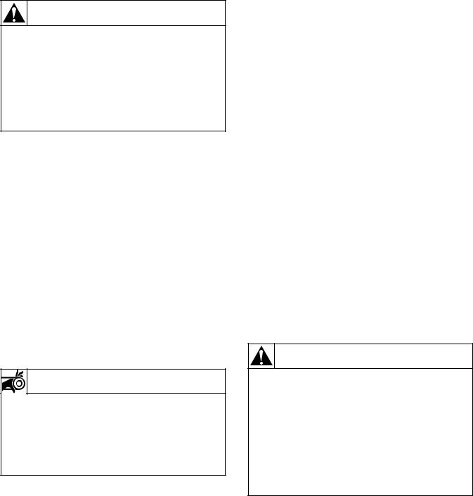
Safety Decals
Safety decals appear at crucial locations on the machine. Failure to maintain legible safety decals could result in injury to the operator or service technician.
MA004G
Figure 1
F232090 |
© Copyright, Alliance Laundry Systems LLC – DO NOT COPY or TRANSMIT |
5 |
Safety Information
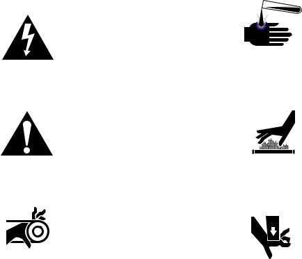
Key To Symbols
The lightning flash and arrowhead within the triangle is a warning sign indicating the presence of dangerous voltage.
The exclamation point within the triangle is a warning sign indicating important instructions concerning the machine and possibly dangerous conditions.
This warning symbol indicates the presence of potentially dangerous drive mechanisms within the machine. Guards should always be in place when the machine is in operation.
This warning symbol indicates the presence of possibly dangerous chemicals. Proper precautions should be taken when handling corrosive or caustic materials.
This warning symbol indicates the presence of hot surfaces that could cause serious burns. Stainless steel and steam lines can become extremely hot and should not be touched.
This warning symbol indicates the presence of possibly dangerous pinch-points. Moving mechanical parts can crush and/or sever body parts.
To provide personal safety and keep the machine in proper working order, follow all maintenance and safety procedures presented in this manual. If questions regarding safety arise, contact the factory immediately.
Use factory-authorized spare parts to avoid safety hazards.
6 |
© Copyright, Alliance Laundry Systems LLC – DO NOT COPY or TRANSMIT |
F232090 |

Operator Safety
WARNING
NEVER insert hands or objects into basket until it has completely stopped. Doing so could result in serious injury.
SW012
To ensure the safety of machine operators, the following maintenance checks must be performed daily:
1.Prior to operating the machine, verify that all warning signs are present and legible. Missing or illegible signs must be replaced immediately. Make certain that spares are available.
2.Check door interlock before starting operation of the machine:
a.Attempt to start the machine with the door open. The machine should not start with the door open.
b.Close the door without locking it and attempt to start the machine. The machine should not start with the door unlocked.
c.Close and lock the door and start a cycle. Attempt to open the door while the cycle is in progress. The door should not open.
If the door lock and interlock are not functioning properly, call a service technician.
3.Do not attempt to operate the machine if any of the following conditions are present:
a.The door does not remain securely locked during the entire cycle.
b.Excessively high water level is evident.
c.Machine is not connected to a properly grounded circuit.
Do not bypass any safety devices in the machine.
WARNING
Never operate the machine with a bypassed or disconnected balance system. Operating the machine with severe out-of-balance loads could result in personal injury and serious equipment damage.
SW039
Safety Information
Safe Operating Environment
Safe operation requires an appropriate operating environment for both the operator and the machine. If questions regarding safety arise, contact the factory immediately.
Environmental Conditions
●Ambient Temperature. Water in the machine will freeze at temperatures of
32° F or below.
Temperatures above 120° F (50° C) will result in more frequent motor overheating and, in some cases, malfunction or premature damage to solid state devices that are used in some models. Special cooling devices may be necessary.
Water pressure switches are affected by increases and decreases in temperature. Every 25° F (10° C) change in temperature will have a 1% effect on the water level.
●Humidity. Relative humidity above 90% may cause the machine’s electronics or motors to malfunction or may trip the ground fault interrupter. Corrosion problems may occur on some metal components in the machine.
If the relative humidity is below 30%, belts and rubber hoses may eventually develop dry rot. This condition can result in hose leaks, which may cause safety hazards external to the machine in conjunction with adjacent electrical equipment.
●Ventilation. The need for make-up air openings for such laundry room accessories as dryers, ironers, water heaters, etc., must be evaluated periodically. Louvers, screens, or other separating devices may reduce the available air opening significantly.
●Elevation. If the machine is to be operated at elevations of over 3,280 feet (1,000 meters) above sea level, pay special attention to water levels and electronic settings (particularly temperature) or desired results may not be achieved.
●Chemicals. Keep stainless steel surfaces free of chemical residues.
F232090 |
© Copyright, Alliance Laundry Systems LLC – DO NOT COPY or TRANSMIT |
7 |
Safety Information
WARNING
Do not place volatile or flammable fluids in any machine. Do not clean the machine with volatile or flammable fluids such as acetone, lacquer thinners, enamel reducers, carbon tetrachloride, gasoline, benzene, naptha, etc. Doing so could result in serious personal injury and/or damage to the machine.
SW002
●Water Damage. Do not spray the machine with water. Short circuiting and serious damage may result. Repair immediately
all seepage due to worn or damaged gaskets, etc.
Machine Location
●Foundation. The concrete floor must be of sufficient strength and thickness to handle the floor loads generated by the high extract speeds of the machine.
●Service/Maintenance Space. Provide sufficient space to allow comfortable performance of service procedures and routine preventive maintenance.
This is especially important in connection with machines equipped with an AC inverter drive.
Consult installation instructions for specific details.
CAUTION
Replace all panels that are removed to perform service and maintenance procedures. Do not operate the machine with missing guards or with broken or missing parts. Do not bypass any safety devices.
SW019
Input and Output Services
●Water Pressure. Best performance will be realized if water is provided at a pressure of 30–85 psi (2.0–5.7 bar). Although the machine will function properly at lower pressure, increased fill times will occur. Water pressure higher than 100 psi (6.7 bar) may result in damage to machine plumbing. Component failure(s) and personal injury could result.
●Steam Heat (Optional) Pressure. Best performance will be realized if steam is provided at a pressure of 30–80 psi (2.0–5.4 bar). Steam pressure higher than 125 psi (8.5 bar) may result in damage to steam components and may cause personal injury.
For machines equipped with optional steam heat, install piping in accordance with approved commercial steam practices. Failure to install the supplied steam filter may void the warranty.
●Compressed Air. For machines requiring compressed air service, best performance will be realized if air is provided at a pressure of 80–100 psi (5.4–6.7 bar).
●Drainage System. Provide drain lines or troughs large enough to accommodate the total number of gallons that could be dumped if all machines on the site drained at the same time from the highest attainable level. If troughs are used, they should be covered to support light foot traffic.
●Power. For personal safety and for proper operation, the machine must be grounded in accordance with state and local codes. The ground connection must be to a proven earth ground, not to conduit or water pipes. Do not use fuses in place of the circuit breaker. An easyaccess cutoff switch should also be provided.
WARNING
Dangerous voltages are present in the electrical control box(es) and at the motor terminals. Only qualified personnel familiar with electrical test procedures, test equipment, and safety precautions should attempt adjustments and troubleshooting. Disconnect power from the machine before removing the control box cover, and before attempting any service procedures.
SW005
Always disconnect power and water supplies before a service technician performs any service procedure. Where applicable, steam and/or compressed air supplies should also be disconnected before service is performed.
8 |
© Copyright, Alliance Laundry Systems LLC – DO NOT COPY or TRANSMIT |
F232090 |
Safety Information
Misuse
Never use this machine for any purpose other than washing fabric.
●Never wash petroleum-soaked rags in the machine. This could result in an explosion.
●Never wash machine parts or automotive parts in the machine. This could result in serious damage to the basket.
●Never allow children to play on or around this machine. Death or serious injury can result if children become trapped in the machine. Do not leave children unattended while the machine door is open. These cautions apply to animals as well.
F232090 |
© Copyright, Alliance Laundry Systems LLC – DO NOT COPY or TRANSMIT |
9 |
Operation
Operation
This manual is designed as a guide to operating and programming the UW35P and UW60P 2-speed and 3-speed rigid-mount washer-extractor equipped with the WE-6 microcomputer.
The UWP washer-extractor features programmable custom cycles and high
extract force.
The manuals, installation instructions, and wiring diagrams which accompany the washer-extractor have been included with the machine at no charge. Additional copies are available at a nominal charge.
NOTE: Read this manual thoroughly before attempting to operate the machine or program the microcomputer.
NOTE: Do not use this manual in conjunction with earlier model microcomputer-controlled UW washer-extractors. Do not use technical literature intended for earlier models when operating this machine.
NOTE: All information, illustrations, and specifications contained in this manual are based on the latest product information available at the time of printing. We reserve the right to make changes at any time without notice.
Delivery Inspection
Upon delivery, visually inspect crate, protective cover, and unit for any visible shipping damage. If the crate, protective cover, or unit are damaged or signs of possible damage are evident, have the carrier note the condition on the shipping papers before the shipping receipt is signed, or advise the carrier of the condition as soon as it is discovered.
Remove the crate and protective cover as soon after delivery as possible. If any damage is discovered upon removal of the crate and/or protective cover, advise the carrier and file a written claim immediately.
Customer Service
If literature or replacement parts are required, contact the source from whom the washer-extractor was purchased or contact Alliance Laundry Systems at (920) 748-3950 for the name and address of the nearest authorized parts distributor.
For technical assistance, call:
(920) 748-3121 Ripon, Wisconsin
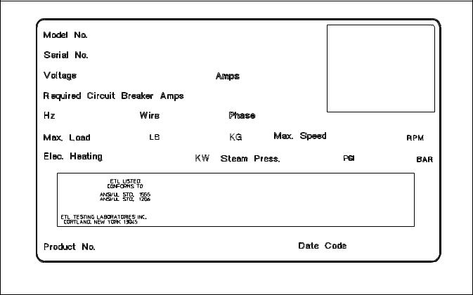
Serial Plate Location
A record of each machine is on file with the manufacturer. Always provide the machine’s serial number and model number when ordering parts or when seeking technical assistance.
Refer to Figure 2.
10 |
© Copyright, Alliance Laundry Systems LLC – DO NOT COPY or TRANSMIT |
F232090 |
Operation
|
Model Number Familiarization Guide |
|
|
|
|
|
Sample Model Number: UW60P2OU70001 |
|
|
|
|
UW |
Model Number Prefix |
|
|
|
|
60 |
Washer-Extractor Capacity (pounds dry weight) |
|
|
|
|
P |
Type of Electrical Control |
P = WE-6 Computer |
|
|
|
2 |
Washer-Extractor Speed Capabilities |
2 = 2 Speeds; 3 = 3 Speeds |
|
|
|
O |
Electrical Characteristics |
|
|
|
|
U7 |
Design Series |
|
|
|
|
0001 |
Option Identification (varies from machine to machine) |
|
|
|
|
UW60P2OU70001 |
|
|
00000000000 |
|
|
220-240 |
11 |
|
|
30 |
|
60 |
3 |
3 |
60 |
27 |
465 |
|
500000 |
|
|
|
PHM549N |
|
SAMPLE DECAL |
|
Figure 2
F232090 |
© Copyright, Alliance Laundry Systems LLC – DO NOT COPY or TRANSMIT |
11 |
Operation
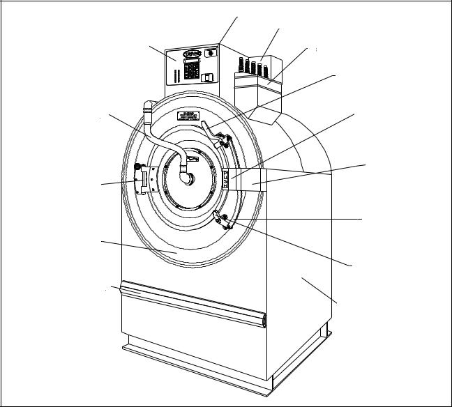
Machine Familiarization Guide
The machine familiarization guide in Figure 3 identifies major operational features of the UWP washer/extractor.
|
Emergency Stop Button |
|
Supply Valve Box |
Control Module |
Supply Dispenser |
|
|
|
Door Latch Handle |
Spray Rinse Tube |
Door Handle |
|
Door Box
Door Hinge
Door Latch
Extension Arm
Shell Front
Door Latch
Rub Rail
Side Panel
FA001G
Figure 3
Theory Of Operation
The design of the washer-extractor emphasizes performance reliability and long service life. The cylinder, shell, and main body panels are fabricated of stainless steel.
Electrical controls for the washer-extractor are housed in a separate enclosure located on the top of the machine. Removing the screws from the module cover, lifting the cover, and pulling to the rear provides
access to the control module. This module contains the WE-6 microcomputer, contactors, water-level switch, and other control components.
One dual-speed motor drives the cylinder via a V-belt drive in both speeds for the 2-speed models. Two motors drive the cylinder for the 3-speed models. The UW35 uses two ball bearings held in place by a single cast-iron housing that is bolted to the A-frame. The UW60 uses two flange-mounted, spherical roller bearings bolted to the A-frame.
12 |
© Copyright, Alliance Laundry Systems LLC – DO NOT COPY or TRANSMIT |
F232090 |
The cylinder is constructed with lifters or ribs that lift the laundry from the bath solution when the cylinder rotates at slow speed and then allow the laundry to tumble back into the bath. This mechanical action accomplishes the washing function. The cylinder is perforated, allowing the water to drain from within during the wash and extract steps.
The spray rinse feature consists of a fiber-reinforced clear hose connected to the center of the door glass and to both a hot and cold water inlet valve. A hemispherically-shaped spray nozzle inside the door glass produces a fan-action water spray which disperses rinse water throughout the load.
The operator can select from among 39 preprogrammed cycles.
Programmable custom cycles are another feature of the UWP.
On the UW60, a balance switch is installed between the faces of the A-frame to signal the controls to slow the machine when a severely out-of-balance load occurs during extract.
Water enters the washer-extractor through electromechanical water valves controlled by the microcomputer. The microcomputer also controls the drain and the door lock. In addition, it selects the water levels according to the programmed cycle. Vacuum breakers are installed in the water-inlet plumbing to prevent backflow of water.
The standard production UWP uses a single drain valve. (Dual drains are available as an option. The dual drains open and close together under control of the WE-6 computer.) The drain valve is normally open, which means that it closes only when power is applied, thus allowing the machine to drain in the event of a power failure.
A door-lock system prevents opening of the stainless steel door when a cycle is in progress. It also prevents operation of the washer-extractor when the door is open. The doorbox contains the door-lock microswitch, door-closed magnetic switch, and the door unlock solenoid.
The UW35 shaft seal assembly includes two lip seals integrated into the cast-iron bearing housing. Each seal has two lips which make contact with a polished stainless steel bushing mounted to the shaft.
Operation
The UW60 shaft seal assembly includes a brass collar held in place on the cylinder shaft with set screws. The collar has a flange with a ceramic ring which makes contact with a spring-loaded phenolic face seal enclosed in a nylon housing mounted on the rear of the shell. The collar contains two internal O rings which maintain contact with the cylinder shaft.
The polypropylene supply dispenser is mounted on the right side of the washer-extractor, viewed from the front. The dispenser has five supply compartments, numbered 1–5, starting from the rear of the machine. The compartments hold plastic supply cups that are used for either liquid or dry supplies. A nozzle flushes supplies from the cups with water for the time programmed in the cycle.
Liquid supplies can be injected directly into the cups by a customer-supplied external chemical supply system. Five hose strain reliefs on top of the supply dispenser facilitate connection to an external supply system. A terminal strip inside a compartment attached to the left side of the control module, viewed from the rear of the washer-extractor, provides connection points for external supply signals.
Emergency Stop Button
A red emergency stop button is located on the upper right-hand corner of the control panel. Push the button in to stop the washer-extractor. Turn button to the left and pull out to reset.
F232090 |
© Copyright, Alliance Laundry Systems LLC – DO NOT COPY or TRANSMIT |
13 |
Operation
WE-6 Microcomputer
The WE-6 microcomputer control is a fieldprogrammable solid-state control capable of storing and running up to 39 preprogrammed ready-to-use cycles. A detailed description of these cycles can be found in the Programming section of this manual under Individual Cycle Charts. (If this machine’s computer has been equipped with special preprogrammed cycles, a separate insert listing these cycles has been included in the resealable plastic bag which contained this manual.)
Never turn the power off while the computer mode switch is in the PROGRAM position. Such action will disorder portions of the programmed data, necessitating reprogramming of some or all of the existing cycles. Always return the mode switch to RUN position before turning the power off.Never leave the mode switch key inserted in the switch lock where it may be accessible to unauthorized personnel not familiar with programming procedures.
The computer control in this washer-extractor is continuously on the alert for problems within the machine. When the computer detects a problem, it immediately flashes a letter or number or both on the display. It may activate the signal buzzer as well.
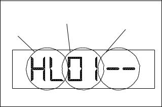
LED Display
The WE-6 microcomputer has a six-digit LED display. References to display indications pertain to the first four digits of the display reading left to right. The last two digits on the right side of the display will indicate either the last cycle used or the current cycle in progress. See Figure 4.
Function |
Step |
Cycle |
Number |
||
Being |
|
Number |
Executed |
|
|
|
|
MC007A |
Figure 4
The table which follows, entitled “Display Interpretations,” lists the various displays and what they mean.
14 |
© Copyright, Alliance Laundry Systems LLC – DO NOT COPY or TRANSMIT |
F232090 |
|
Display Interpretations |
|
|
|
|
UWP_01 |
Program identification code (ROM). |
|
This is an example only. |
||
|
||
|
|
|
DONE |
End of cycle |
|
|
|
|
DOOR |
Door not locked problem |
|
|
|
|
EMTY |
Empty problem |
|
|
|
|
FILL |
Fill problem |
|
|
|
|
SDLY |
Spin coast delay |
|
|
|
|
NEXT |
Select cycle or open door or select |
|
program |
||
|
||
|
|
|
NCYC |
Cycle not available |
|
|
|
|
STOP |
Stop button pressed or cycle ended |
|
|
|
|
A1 |
Auxiliary output #1 |
|
|
|
|
A2 |
Auxiliary output #2 |
|
|
|
|
A3 |
Signal |
|
|
|
|
CF |
Cold flush |
|
|
|
|
CH |
Cold fill to high level |
|
|
|
|
CM |
Cold fill to medium level |
|
|
|
|
CL |
Cold fill to low level |
|
|
|
|
CO |
Cold fill to overflow |
|
|
|
|
CR |
Cold rinse |
|
|
|
|
CY |
Cycle number |
|
|
|
|
D1 |
Drain #1 |
|
|
|
|
D2 |
Drain #2 (This feature is operational on |
|
UWPV models only.) |
||
|
||
|
|
|
F |
Heat select temperature in ° Fahrenheit |
|
|
|
|
C |
Heat select temperature in ° Centigrade |
|
|
|
|
HF |
Hot flush |
|
|
|
|
HH |
Hot fill to high level |
|
|
|
|
HM |
Hot fill to medium level |
|
|
|
|
HL |
Hot fill to low level |
|
|
|
Operation
|
Display Interpretations (Continued) |
|
|
|
|
HO |
|
Hot fill to overflow |
|
|
|
HR |
|
Hot rinse |
|
|
|
HS |
|
High speed spin |
|
|
|
MS |
|
Medium speed spin |
|
|
|
HT |
|
Heat (steam or electric) |
|
|
|
--M |
|
Minutes (used when programming |
|
time) |
|
|
|
|
|
|
|
--S |
|
Seconds (used when programming |
|
time) |
|
|
|
|
|
|
|
SK |
|
Soak |
|
|
|
S1 |
|
Supply #1 (Detergent) |
|
|
|
S2 |
|
Supply #2 (Bleach) |
|
|
|
S3 |
|
Supply #3 (Sour) |
|
|
|
S4 |
|
Supply #4 (Softener) |
|
|
|
S5 |
|
Supply #5 (Specialty) |
|
|
|
TH |
|
Controlled temperature fill to high |
|
level |
|
|
|
|
|
|
|
TM |
|
Controlled temperature fill to medium |
|
level |
|
|
|
|
|
|
|
TL |
|
Controlled temperature fill to low level |
|
|
|
TO |
|
Controlled temperature overflow |
|
|
|
W1 |
|
Wash #1 (normal reversing) |
|
|
|
W2 |
|
Wash #2 (gentle reversing) |
|
|
|
W3 |
|
Wash #3 (no agitation) |
|
|
|
W4 |
|
Wash #4 (distribution speed–forward |
|
only) |
|
|
|
|
|
|
|
W5 |
|
Wash #5 (temp.-controlled cool-down) |
|
|
|
WF |
|
Warm flush |
|
|
|
WH |
|
Warm fill to high level |
|
|
|
WM |
|
Warm fill to medium level |
|
|
|
WL |
|
Warm fill to low level |
|
|
|
F232090 |
© Copyright, Alliance Laundry Systems LLC – DO NOT COPY or TRANSMIT |
15 |
Operation
Display Interpretations (Continued) |
||
|
|
|
WO |
Warm fill to overflow level |
|
|
|
|
WR |
Warm rinse |
|
|
|
|
• |
Left dot–poor balance condition |
|
|
|
|
• |
Second dot from left–door lock switch |
|
|
|
|
• |
Third dot from left–program mode |
|
|
|
|
• |
Fourth dot from left–high level reached |
|
|
|
|
• |
Fifth dot from left–medium level |
|
reached |
||
|
||
|
|
|
• |
Right dot–low level reached |
|
|
|
|
EXISTS |
Cycle already in memory |
|
|
|
|
EDIT? |
Do you want to edit the cycle? |
|
|
|
|
TEMP |
Over-temperature-limit condition |
|
|
|
|
|
Open or shorted temperature input |
|
OVERHT |
circuit or temperature out of |
|
|
computer’s allowable limits |
|
|
|
|
WATER |
Water in washer-extractor at end of |
|
cycle |
||
|
||
|
|
|
°FAR |
Temperature in degrees Fahrenheit |
|
|
|
|
°CEN |
Temperature in degrees Centigrade |
|
|
|
|
MANUAL |
Manual Mode enabled |
|
|
|
|
NO MAN |
Manual Mode disabled |
|
|
|
|
1DRAIN |
One drain capability selected |
|
|
|
|
|
Second independent drain enabled via |
|
|
Auxiliary 2 output. (This feature is |
|
2Drain |
operational on UWPV models only. |
|
|
and should not be confused with the |
|
|
“dual drain” option.) |
|
|
|
|
ADV |
Advance (skip steps) feature enabled |
|
|
|
|
NO ADV |
Advance feature disabled |
|
|
|
|
16 |
© Copyright, Alliance Laundry Systems LLC – DO NOT COPY or TRANSMIT |
F232090 |
Operation
Operational Keypad
The computer’s control keypad includes sixteen keys. See Figure 5. Fourteen of these keys list functions printed in black lettering on a silver background. These functions are available to the operator and are intended to control operation of the machine. See the table below.
|
Operational Keypad |
|
|
|
|
Key |
Description |
|
|
|
|
Numbers 0–9 |
Press to select cycle number. |
|
|
|
|
Display Temp |
Press and hold. Display will show and update sump temperature in degrees Fahrenheit or Centigrade. |
|
|
|
|
|
Press to cause computer to skip to the next step in the cycle. The computer will not advance past |
|
Advance |
drain step if machine is not empty. (The Advance key is enabled at the factory and can be disabled at |
|
the |
||
|
||
|
laundry site.) |
|
|
|
|
Stop |
Press to immediately abort the cycle and initiate the Stop Routine. |
|
|
|
|
Start |
Press to start selected cycle or to re-start a step following a “FILL” or “EMTY” alarm. See Error |
|
Recovery Routine in this section of the manual. |
||
|
||
|
|
|
Manual |
See Manual Mode Control Feature at the end of this section. |
|
|
|
F232090 |
© Copyright, Alliance Laundry Systems LLC – DO NOT COPY or TRANSMIT |
17 |
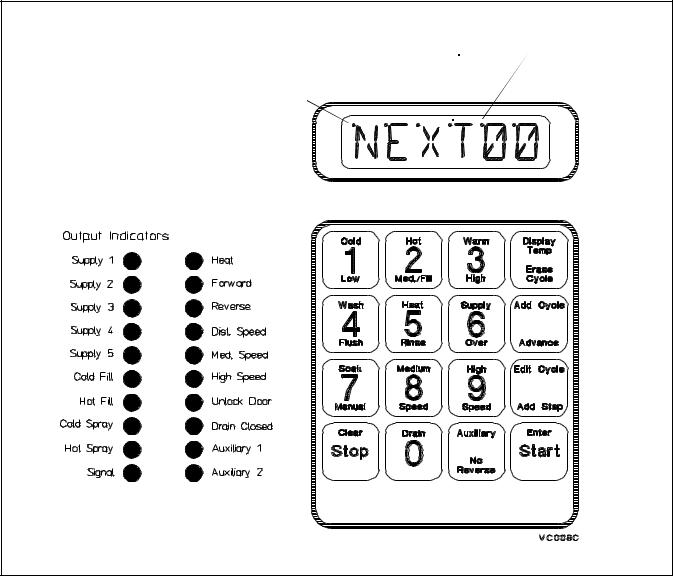
Operation
Located to the left of the computer keyboard are 20 LED indicator lights for the computer outputs. During the time that a cycle is running, one or more of these lights will be on to indicate the outputs activated for a particular step. See Figure 5.
Program |
High Level |
Medium Level |
|||
Door Lock Mode |
|||||
Fill Indicator |
Fill Indicator |
||||
Switch |
|
|
Low Level |
||
|
|
|
|||
Balance Sensing |
|
|
Fill Indicator |
||
Indicator |
|
|
|
|
|
|
|
|
|
|
|
|
|
|
|
|
|
MC008G
Figure 5
Start-up
Turn on the main power source (circuit breaker or cutoff switch on the wall).
When AC power is turned on, the display will show the program (ROM) identification code.
This identification code will appear for approximately five seconds. Then the computer display will flash “POWER” and “WAIT” alternately for 30 seconds.
The display will then show “NEXT00” to indicate that a cycle can be selected. This display will be shown at all times that power is on between cycles, indicating that the door-unlock solenoid will function if the doorunlock button is pressed. The washer-extractor is then ready for loading and unloading.
18 |
© Copyright, Alliance Laundry Systems LLC – DO NOT COPY or TRANSMIT |
F232090 |
 Loading...