


Washer/Extractor
AC Adjustable Frequency
Drive Information
For Allen-Bradley Model Numbers:
160
1305
1336
PowerFlex 40
PowerFlex 400
U072M
PHM1396C
TMB1396C
U074M |
FAULT |
|
READY |
||
|
U071M U071
U073M
Supplement
Part No. F232120R6
January 2010
|
|
Supplement |
|
General Information........................................................................... |
3 |
Table of |
Nameplate Location.............................................................................. |
4 |
Contents |
Storage .................................................................................................. |
5 |
|
General Inspection ................................................................................ |
5 |
|
PowerFlex 40 and 400 Drive Control Logic ..................................... |
6 |
|
Installation/Wiring................................................................................ |
6 |
|
Input Power Conditioning................................................................ |
6 |
|
Electrical Interference...................................................................... |
7 |
|
Terminal Block Access .................................................................... |
8 |
|
Power Terminal Block Description ................................................. |
9 |
|
Control Terminal Blocks Description and Control Logic................ |
10 |
|
AC Drive Diagnostics/Parameter Viewing........................................... |
28 |
|
PowerFlex Integrated Keypad.......................................................... |
28 |
|
Fault Display and Troubleshooting Information .................................. |
32 |
|
Allen-Bradley Drive Fault Codes .................................................... |
33 |
|
Troubleshooting Suggestions........................................................... |
35 |
|
Allen-Bradley 160-Series AC Drives................................................. |
36 |
|
Installation/Wiring................................................................................ |
36 |
|
Input Power Conditioning................................................................ |
36 |
|
Electrical Interference...................................................................... |
37 |
|
Terminal Block Access .................................................................... |
39 |
|
Power Terminal Block Description ................................................. |
40 |
|
Control Terminal Blocks Description and Control Logic................ |
41 |
|
160 Series Drive Control Logic Chart ............................................. |
42 |
|
AC Drive Diagnostics/Parameter Viewing........................................... |
51 |
|
160 Program Keypad Module (PKM or Parameter Unit)................ |
51 |
|
CopyCat Keypad.............................................................................. |
54 |
|
Fault Display and Troubleshooting Information .................................. |
58 |
|
Fault Code Identification ................................................................. |
58 |
|
Allen-Bradley Drive Fault Codes .................................................... |
59 |
|
Troubleshooting Suggestions........................................................... |
61 |
|
Allen-Bradley 1305-Series AC Drives............................................... |
62 |
|
Installation/Wiring................................................................................ |
62 |
|
Input Power Conditioning................................................................ |
62 |
|
Electrical Interference...................................................................... |
63 |
|
Terminal Block Access .................................................................... |
64 |
|
Power Terminal Block Description ................................................. |
65 |
|
Control Terminal Blocks Description and Control Logic................ |
65 |
|
AC Drive Diagnostics/Parameter Viewing........................................... |
73 |
|
Human Interface Module (HIM or Parameter Unit) ........................ |
73 |
|
HIM Structure Chart – Series A 3.00, Series B 1.01 |
|
|
or Later Versions................................................................................ |
75 |
|
HIM Structure Chart – Earlier Versions............................................... |
76 |
|
Fault Display and Troubleshooting Information .................................. |
80 |
|
Fault Code Identification ................................................................. |
80 |
|
Allen-Bradley Drive Fault Codes .................................................... |
81 |
|
Troubleshooting Suggestions........................................................... |
83 |
© Copyright 2010, Alliance Laundry Systems LLC
All rights reserved. No part of the contents of this book may be reproduced or transmitted in any form or by any means without the expressed written consent of the publisher.
F232120 |
© Copyright 2006, Alliance Laundry Systems LLC – DO NOT COPY or TRANSMIT |
1 |
Supplement
Allen-Bradley 1336-Series AC Drives............................................... |
84 |
Installation/Wiring................................................................................ |
84 |
Input Power Conditioning................................................................ |
84 |
Electrical Interference...................................................................... |
85 |
Terminal Block Access .................................................................... |
86 |
Power Terminal Block Description ................................................. |
87 |
Control Terminal Blocks Description and Control Logic................ |
88 |
AC Drive Diagnostics/Parameter Viewing........................................... |
98 |
Human Interface Module (HIM or Parameter Unit) ........................ |
98 |
HIM Structure Chart – Series A 3.00, Series B 1.01 |
|
or Later Versions ............................................................................ |
100 |
HIM Structure Chart – Earlier Versions .......................................... |
101 |
Fault Display and Troubleshooting Information .................................. |
105 |
Fault Code Identification ...................................................................... |
105 |
Allen-Bradley Drive Fault Codes .................................................... |
107 |
Troubleshooting Suggestions........................................................... |
109 |
2 |
© Published by permission of the copyright owner – DO NOT COPY or TRANSMIT |
F232120 |
General Information
General Information
•This drive contains ESD (Electrostatic Discharge) sensitive parts and assemblies. Static control precautions are required when installing, testing, or servicing this assembly. Component damage may result if ESD control procedures are not followed.
•An incorrectly applied or installed drive can result in component damage or a reduction in product life. Wiring or application errors, such as incorrect or inadequate AC supply or excessive ambient temperatures, may result in malfunction of the system.
•This drive contains power storage devices that retain their charge for a time after the removal of main power. Extreme caution should be used when working in and around the drive. It is recommended that main disconnect power to the drive remain off for three minutes prior to approaching connections.
Warnings specific to a particular subject will appear in the manual with the discussion of that subject.
CAUTION
Only personnel familiar with the drive and associated machinery should plan or implement the installation, start-up, and subsequent maintenance of the system. Failure to comply may result in personal injury and/or equipment damage.
W659
F232120 |
© Copyright, Alliance Laundry Systems LLC – DO NOT COPY or TRANSMIT |
3 |
General Information
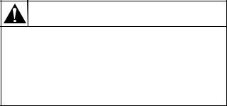
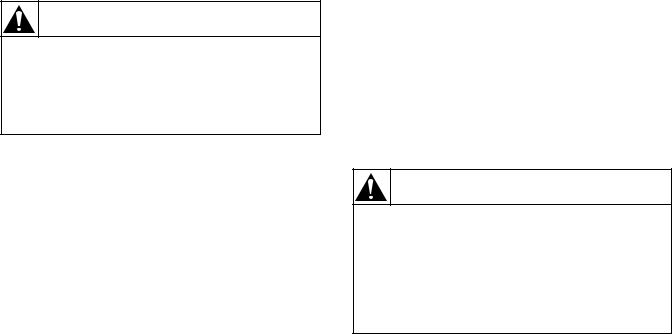
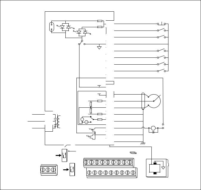
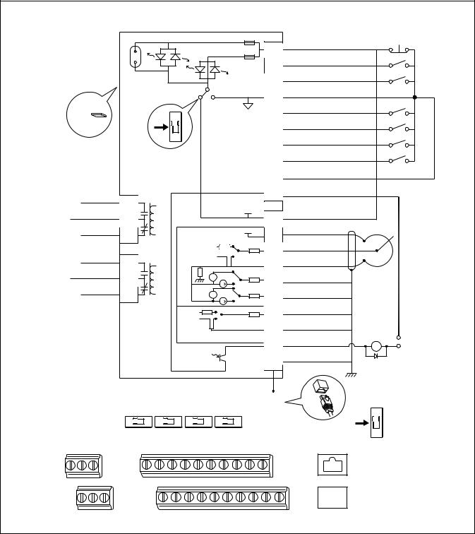
Nameplate Location
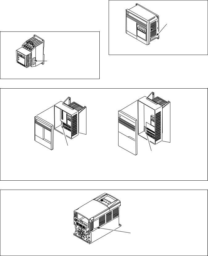
Pertinent drive information used in obtaining information on drive operation or replacement is located on the nameplate shown in Figures 1 through 4.
FAULT |
Nameplate Located on |
|
|
READY |
Exterior of Enclosure |
|
160 NAMEPLATE LOCATION
U146ME3A
Figure 1
Nameplate Located on
Exterior of Enclosure
1305 NAMEPLATE LOCATION |
U072ME3A |
|
|
|
U072ME3A |
Figure 2
|
|
|
|
|
|
|
|
|
|
|
|
|
|
|
|
|
|
|
|
|
|
|
|
|
|
|
|
|
|
|
|
|
|
|
|
|
|
|
|
|
|
|
|
|
|
|
|
|
Nameplate Located |
|
|||||
on Bottom Portion of |
Nameplate Located |
|||||
Chassis Behind Cover |
||||||
on Mounting Plate of |
||||||
|
|
|
|
|
||
|
|
|
|
|
Main Control Board |
|
FRAMES A1, A2, A3, A4 |
FRAMES B-G |
|
U147ME3A |
1336 PLUS NAMEPLATE LOCATION
U147ME3A
Figure 3
Nameplate Located on
Exterior of Enclosure.
TMB1396C
POWERFLEX NAMEPLATE LOCATION
PHM1396C
Figure 4
4 |
© Copyright, Alliance Laundry Systems LLC – DO NOT COPY or TRANSMIT |
F232120 |
General Inspection
Upon delivery, verify the item’s nameplate catalog number against the purchase order.
Before the installation and start-up of the drive, a general inspection of the mechanical integrity (i.e., loose parts, wires, connections, etc.) should be made.
General Information
Storage
The drive should remain in its shipping container prior to installation. If the equipment is not to be used for a period of time, it must be stored according to the following instructions in order to maintain warranty coverage:
•Store in a clean, dry location.
•Store within an ambient temperature range of -40 to 70 degrees C.
•Store within a relative humidity range of 0 to 95 percent.
•Do not store equipment where it could be exposed to a corrosive atmosphere.
•Do not store equipment in a construction area.
F232120 |
© Copyright, Alliance Laundry Systems LLC – DO NOT COPY or TRANSMIT |
5 |

PowerFlex 40 and 400 Drive Control Logic
PowerFlex 40 and 400 Drive Control Logic
Installation/Wiring
CAUTION
An incorrectly installed system can result in component damage or reduction in product life. The most common causes are:
1.Wiring AC line to drive output or control terminals.
2.EXTERNAL voltage application to control terminals.
3.Incorrect or inadequate AC supply.
Contact factory for assistance with application or wiring.
W660
Input Power Conditioning
The drive is suitable for direct connection to input power within the rated voltage of the drive. Listed in
Table 1 are certain input power conditions which may cause component damage or reduction in product life. If any of the conditions exist, as described in Table 1, install one of the devices listed under the heading Corrective Action on the line side of the drive.
IMPORTANT: Only one device per branch circuit is required. It should be mounted closest to the branch and sized to handle the total current of the branch circuit.
Input Power Condition |
|
Corrective Action |
|
|
|
|
|
Low Line impedance (less than 1% line reactance) |
• |
Install Line Reactor |
|
|
• |
or Isolation Transformer |
|
Greater than 120 kVA supply transformer |
|||
• |
or Bus Inductor – 5.5 & 11kW (7.5 & 15 HP) drives |
||
|
|||
|
|
only |
|
|
|
|
|
Line has power factor correction capacitors |
• |
Install Line Reactor |
|
|
• |
or Isolation Transformer |
|
Line has frequent power interruptions |
|||
|
|
||
|
|
|
|
Line has intermittent noise spikes in excess of 6000V |
|
|
|
(lightning) |
|
|
|
|
|
|
|
Phase to ground voltage exceeds 125% of normal line to line |
• |
Remove MOV jumper to ground. |
|
voltage |
• |
or Install Isolation Transformer with grounded |
|
|
|
secondary |
|
Ungrounded distribution system |
|
||
|
if necessary |
||
|
|
||
|
|
|
|
240V open delta configuration (stinger leg) (1) |
• |
Install Line Reactor |
(1) For drives applied on an open delta with a middle phase grounded neutral system, the phase opposite the phase that is tapped in the middle to the neutral or earth is referred to as the “stinger leg,” “high leg,” “red leg,” etc. This leg should be identified throughout the system with red or orange tape on the wire at each connection point. The stinger leg should be connected to the center Phase B on the reactor.
Table 1
6 |
© Copyright, Alliance Laundry Systems LLC – DO NOT COPY or TRANSMIT |
F232120 |
Electrical Interference
EMI
Careful attention must be given to the arrangement of power and ground connections to the drive to avoid interference with nearby sensitive equipment. Be sure to replace all ground connections to their appropriate locations.
RFI
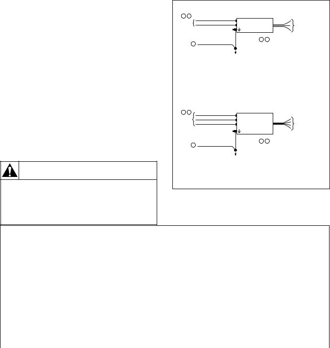
Drives can be installed with an RFI filter, which controls high-frequency conducted emissions into the main supply lines.
Where it is essential that very low emission levels must be achieved or if conformity with standards is required, the optional RFI filter may be present. Figure 5 displays an electrical schematic for various RFI configurations. Table 2 shows associated RFI filter part numbers.
CAUTION
ELECTRIC SHOCK HAZARD! Service and
maintenance to be performed only by an authorized technician. Disconnect power before opening any access panels.
W661
PowerFlex 40 and 400 Drive Control Logic
SINGLE PHASE MACHINES
1 |
2 |
|
|
|
|
|
INPUT |
L1 |
LINE |
ALLEN-BRADLEY |
LOAD |
||
POWER |
L2 |
RFI |
||||
|
|
|||||
|
|
|
|
FILTER |
|
|
|
|
|
|
2 |
3 |
|
|
3 |
PROVEN EARTH GROUND |
|
TO AC DRIVE UNIT Ð |
||
|
|
|
|
GREEN-YELLOW WIRE MUST CONNECT TO |
||
|
|
|
|
AC DRIVE GROUND TERMINAL. |
||
WASHING |
BLACK WIRES WILL CONNECT TO AC DRIVE |
|
INPUT TERMINALS "R", "S" & "T". |
||
MACHINE |
||
BLACK WIRES ARE NOT LABELED AND THEIR |
||
GROUNDING |
||
RESPECTIVE TERMINATION IN AC DRIVE IS |
||
TERMINAL |
||
NOT OF IMPORTANCE. |
||
|
THREE PHASE MACHINES
1 |
2 |
|
|
|
|
INPUT |
L1 |
LINE |
ALLEN-BRADLEY |
|
|
L2 |
|
LOAD |
|||
POWER |
RFI |
||||
|
|
L3 |
|
|
|
|
|
|
FILTER |
|
|
|
|
|
|
|
|
|
|
|
|
2 |
3 |
|
3 |
PROVEN EARTH GROUND |
|
TO AC DRIVE UNIT Ð |
|
|
|
|
|
GREEN-YELLOW WIRE MUST CONNECT TO |
|
|
|
|
|
AC DRIVE GROUND TERMINAL. |
|
WASHING |
BLACK WIRES WILL CONNECT TO AC DRIVE |
|
INPUT TERMINALS "R", "S" & "T". |
||
MACHINE |
||
BLACK WIRES ARE NOT LABELED AND THEIR |
||
GROUNDING |
||
RESPECTIVE TERMINATION IN AC DRIVE IS |
||
TERMINAL |
||
NOT OF IMPORTANCE. |
||
|
||
|
U166ME3A |
U166ME3A
Figure 5
RFI Filter Part Number Information
Drive P/N |
Drive Catalog |
|
Machine Voltage |
Filter P/N |
F8044301 and F8168603 |
22B-B017N104xx |
|
200-240V 50-60Hz 3 phase |
F8053901 |
F8044401 and F8168604 |
22B-D010N104xx |
|
380-480V 50-60Hz 3 phase |
F8053902 |
|
|
|
|
|
F8044701 and F8168601 |
22B-B012N104xx |
|
200-240V 50-60 Hz 3 Phase |
F8053901 |
|
|
|
|
|
F8044901 and F8168602 |
22B-D6P0N104xx |
|
380-480V 50-60 Hz 3 Phase |
F8053902 |
C002501 and F8168701 |
22B-B024N104xx |
|
200-240V 50-60 Hz 3 Phase |
F8054001 |
|
|
|
|
|
C002502 and F8168702 |
22B-D012N104xx |
|
380-480V 50-60 Hz 3 Phase |
F8054002 |
|
|
|
|
|
C002507 and F8168705 |
22B-D024N104xx |
|
380-480V 50-60 Hz 3 Phase |
C002569 |
C002502, F200309300 |
22B-B033N104Axx |
|
200-240V 50-60Hz 3 phase |
F8054001 |
and F8168703 |
|
|
|
|
C002506, F200309400 |
22B-D017N104Axx |
|
380-480V 50-60Hz 3 phase |
F8054002 |
and F8168704 |
|
|
|
|
|
|
Table 2 |
|
|
F232120 |
© Copyright, Alliance Laundry Systems LLC – DO NOT COPY or TRANSMIT |
7 |
PowerFlex 40 and 400 Drive Control Logic
Terminal Block Access
WARNING
To reduce risk of electric shock, severe injury or death, allow machine power to remain off for three minutes minimum prior to working in and around AC drive. Proceed with caution.
W662
The following information illustrates the terminal block designations for each of the drive models.
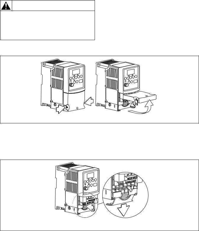
Opening the Cover
1.Press and hold in the tabs on each side of the cover. Refer to Figure 6.
2.Pull the cover out and up to release.
COVER
PHM636N
Figure 6
Power Terminal Block
The drive utilizes a finger guard over the power wiring terminals. To remove:
1. Press in and hold the locking tab.
2.Slide finger guard down and out. Refer to
Figure 7.
3.Replace the finger guard when wiring is complete.
POWER TERMINAL BLOCK (TYPICAL)
PHM637N
Figure 7
8 |
© Copyright, Alliance Laundry Systems LLC – DO NOT COPY or TRANSMIT |
F232120 |
Power Terminal Block Description
PowerFlex 40
Input and Output Power Terminals (TB1)
B Frame
R/L 1 S/L 2 T/L 3 U/T 1 V/T 2 W/T 3
DC- |
DC+ |
BR+ |
BR- |
PHM741N
Figure 8
PowerFlex 40
Power Block Terminal (TB1)
Terminal |
Description |
R/L1, S/L2, T/L3 |
Single-phase or |
|
3-phase Power Input |
U/T1, V/T2, W/T3 |
3-phase Motor Output |
DC-1, DC+, -DC |
DC Bus Connection |
|
|
|
Ground Connection (PE) |
|
|
Table 3
PowerFlex 40
Power Terminal Block
Torque |
|
1.7-2.2 N-m (16-19 lb-in) |
|
|
|
Max Wire Size |
|
5.3 mm2 (10 AWG) |
Min Wire Size |
|
1.3 mm2 (16 AWG) |
|
Table 4 |
|
PowerFlex 40 and 400 Drive Control Logic
PowerFlex 400
Input and Output Power Terminals (TB1)
Frame D
R/L 1 |
S/L 2 |
T/L 3 |
P 1 |
P 2 |
DC- |
|
|
|
|
U/T 1 |
V/T 2 W/T 3 |
||||
|
|
|
|
||||
|
|
|
|
|
|
PHM742N
Figure 9
PowerFlex 400
PowerFlex Power Block Terminal (TBI)
Terminal |
|
Description |
R/L1, S/L2, T/L3 |
|
3-phase Power Input |
|
|
|
U/T1, V/T2, W/T3 |
|
3-phase Motor Output |
|
|
|
P1, P3 |
|
DC Bus inductor connection |
|
|
jumper or Bus inductor must |
|
|
be present for drive to power- |
|
|
up. |
P2, DC- |
|
DC Bus Connection |
|
|
Ground Connection (PE) |
|
|
|
|
Table 5 |
|
PowerFlex 400 |
|
|
Power Terminal Block
Torque |
|
5.1N-m (45 lb-in) |
Max Wire Size |
|
33.6 mm2 (2 AWG) |
Min Wire Size |
|
8.4 mm2 (8 AWG) |
|
Table 6 |
|
F232120 |
© Copyright, Alliance Laundry Systems LLC – DO NOT COPY or TRANSMIT |
9 |
PowerFlex 40 and 400 Drive Control Logic
Control Terminal Blocks Description and
Control Logic
WARNING
To reduce risk of electric shock, severe injury or death, allow machine power to remain off for three minutes minimum prior to working in and around AC drive. Proceed with caution.
W662
NOTE: Do not connect AC drive digital common, analog common, or common terminals to chassis ground.
Input Mode Parameter
The control terminal functions are determined in part by the “Start Source” parameter #36. Changing this parameter affects the function of some terminals.
Speed Selection
Motor speeds on digitally-controlled AC drives are controlled by solid state or mechanical switch closure inputs to Digital In 1, Digital In 2, and Digital In 3 terminals. Similarly, motor rotation direction is controlled by inputs to Start/Run FWD and Direction/ Run REV terminals. Refer to Figure 10.
An inactive control input terminal (H) will measure approximately 24v DC while an active control input terminal (L) will measure less than 1v DC. When a control input (i.e., Digital In 1, 2, 3, 4, Fwd, Rev, or Stop) is connected to a common terminal (terminal 4), the voltage on the control input terminal is reduced to near zero and the input is activated.
Tables 8 – 14 designate the speed and rotation direction based on inputs to the control terminals. The AC drive’s input status parameters display of 1s and 0s at various machine actions can be viewed while monitoring parameter #13 and/or #14. When the control input terminal voltage is high (inactive) the status display will read “0” (logic 0). When the control input terminal voltage is low (active) the status will read “1” (logic 1).
Balance Output
The AC drive balance output signal is transmitted to the machine controller by the operation of an on-board normally open relay or transistor. Refer to Figure 10. The AC drive will analyze the wash load distribution during certain drain steps and communicate the severity of load imbalance to the machine controller. The machine controller then determines if the load is suitably distributed for the programmed spin speed. The severity of load imbalance is communicated digitally by the on-board relay or transistor using a series of pulses or continuous open or closed state.
CAUTION
Never permanently jumper the AC drive balance output terminals or short the wires in these terminals together. This will override the balance detection routine and cause the wash cycle to abort, potentially causing machine damage or personal injury in the process.
W671
Stop/Enable Input
The Stop Input function is machine dependent. The input is typically used to disable the drive either when the frame vibration safety limit switch has been tripped or when the loading door has been opened. Refer to the applicable machine electrical schematic for details on the connection of this input. When the Stop Input signal is interrupted, the control input signals must be removed and reapplied to restart the motor operation.
10 |
© Copyright, Alliance Laundry Systems LLC – DO NOT COPY or TRANSMIT |
F232120 |
Sink/Source Switch
The PowerFlex series of drives include a DIP Switch that will allow the drive input signals to be wired as “sink” or “source”. This switch should be set to the sink mode on all Alliance Laundry equipment made at the time of this publication. Setting this switch in the source mode will cause the drive to not operate and be mistaken as a failed drive.
PowerFlex 40 and 400 Drive Control Logic
0-10V/0-20m A Switch
The PowerFlex series of drives include a DIP switch that will allow the drive analog input signals to be wired as a 0-10V/0-20 mA switch.This switch should be set to the 0-10V mode on all Alliance Laundry Equipment made at the time of this publication. Setting this switch in the 0-20 mA mode may cause the drive to not operate and be mistaken as a failed drive.
Fault Code Display
Refer to Fault Display and Troubleshooting Information.
F232120 |
© Copyright, Alliance Laundry Systems LLC – DO NOT COPY or TRANSMIT |
11 |
PowerFlex 40 and 400 Drive Control Logic
PowerFlex 40 Control Terminal Block
Designations
Control Wiring Block Diagram |
|
|
|
|
|
|
|
|
|
|
||
|
Enable |
|
|
|
|
|
|
|
|
|
|
Typical |
|
Jumper |
|
|
|
|
|
|
|
|
|
|
|
|
|
|
|
|
|
|
Stop |
|
|
|
SNK Wiring |
|
|
|
|
|
|
|
|
|
|
|
|
||
|
|
|
|
|
|
01 |
|
|
|
|
|
|
|
|
|
|
|
|
02 |
FWD |
|
|
|
||
|
|
|
|
|
|
|
|
|
|
|
||
|
|
|
|
|
|
03 |
REV |
|
|
|
|
|
|
|
|
|
|
|
|
|
|
|
|
||
|
SNK |
SRC |
|
|
04 |
Digital Common |
|
|||||
|
|
|
|
|
|
|
|
|||||
|
|
|
|
|
|
|
|
|
|
|
||
|
|
|
|
|
|
05 |
Digital Input 1 |
|
|
|||
|
|
|
|
|
|
|
|
|
|
|
||
|
|
|
|
|
|
06 |
Digital Input 2 |
|
|
|||
|
|
|
|
|
|
|
|
|
|
|
||
|
|
|
|
|
|
07 |
Digital Input 3 |
|
|
|||
|
|
|
|
|
|
|
|
|
|
|
||
|
|
|
|
|
|
08 |
Digital Input 4 |
|
|
|||
|
|
|
|
|
|
|
|
|
|
|
||
|
|
|
|
|
|
09 |
Bal Common |
|
|
|||
|
|
|
|
|
|
|
|
|
|
|
||
|
|
|
|
+24V |
|
|
+ 24V DC |
|
|
|
||
|
|
|
|
|
|
11 |
|
|
|
|||
|
|
|
|
|
|
|
|
|
|
|
||
|
|
|
|
+10V |
12 |
+ 10V DC |
|
|
|
|||
|
|
|
|
|
|
|
|
|
|
|
||
|
|
|
|
|
|
13 |
0-10V ( or ± 10V) Input |
|
||||
|
|
|
|
|
|
|
|
|
|
|
||
|
|
|
|
|
|
14 |
Analog Common |
|
||||
|
|
|
|
|
|
|
|
|
|
Pot must be |
||
|
|
|
|
|
|
|
|
|
|
|
|
|
Relay N.O. |
R1 |
|
|
|
|
15 |
4-20mA Input |
|
1-10k ohm |
|||
|
|
0-10V |
|
|
|
|
|
1 Watt Min. |
||||
|
|
|
|
|
|
|
|
|
|
|
||
Relay Common |
|
+ |
|
|
|
|
|
Analog Output |
|
|
||
R2 |
- |
0/4-20mA |
16 |
|
|
|||||||
|
|
|
|
|
|
Common |
||||||
|
|
|
|
|
|
|
|
Bal Output |
|
|||
Relay N.C. |
R3 |
|
|
|
|
17 |
|
24V |
||||
|
|
|
|
|
|
|
|
|
|
|||
|
|
|
|
|
|
18 |
Opto Output 2 |
|
|
|||
|
30V DC |
|
|
|
|
|
|
|
|
|||
|
|
|
|
|
|
|
|
|
|
|
||
|
50mA |
|
|
|
|
|
RS485 Shield |
|
|
|||
|
Non-inductive |
|
|
19 |
|
|
||||||
|
|
|
|
|
|
|
|
|||||
|
0-10V |
Analog Output Select |
|
|
|
ENBL |
Enable |
|
||||
|
|
|
|
|
|
|
|
|
Jumper |
|
||
|
|
01 |
02 |
03 |
04 |
05 |
06 |
07 |
08 |
09 |
|
|
|
|
|
|
|||||||||
|
0-20mA |
|
|
|
|
|
|
|
|
|
|
|
R1 R2 R3 |
|
|
|
|
|
|
|
|
|
|
|
|
|
SNK |
|
|
|
|
|
|
|
|
|
|
RS485 |
|
|
|
11 |
12 |
13 |
14 |
15 |
16 |
17 |
18 |
19 |
|
|
|
|
(DSI) |
|||||||||
|
SRC |
|
|
|
|
|
|
|
|
|
|
|
PHM780N
Figure 10
Control Input/Output Terminal Block
Torque |
|
0.5-0.8 N-m (4.4-7.0 lb-in) |
|
|
|
Max Wire Size |
|
1.3 mm2 (16 AWG) |
Min Wire Size |
|
0.13 mm2 (26 AWG) |
|
Table 7 |
|
12 |
© Copyright, Alliance Laundry Systems LLC – DO NOT COPY or TRANSMIT |
F232120 |
PowerFlex 40 and 400 Drive Control Logic
PowerFlex 400 Control Terminal Block
Designations
Control Wiring Block Diagram
ENBL
#1 Relay N.O.
#1 Relay Common
#1 Relay N.C.
#2 Relay N.O.
#2 Relay Common
#2 Relay N.C.
1 of 7 Digital Input Circuits |
01 |
|
02 |
Enable |
|
|
|
|
03 |
|
Jumper |
SNK |
|
SRC |
|
||
|
|
|
04 |
|||
|
|
|
|
|
|
|
|
SNK |
|
|
|
05 |
|
|
|
|
|
|
||
|
|
|
|
|
|
06 |
|
SRC |
|
|
|
|
|
|
|
|
|
|
|
07 |
|
|
|
|
|
|
08 |
|
|
|
|
|
|
09 |
|
|
|
|
|
|
10 |
R1 |
|
|
|
|
|
|
|
|
|
|
|
+24V |
|
R2 |
|
|
|
|
|
11 |
R3 |
|
Earth Referenced |
+10V |
12 |
||
|
|
|||||
|
Frames D & E |
|
||||
|
|
0-10V |
|
|||
|
|
|
|
|
13 |
|
|
|
|
|
|
|
|
R4 |
|
|
|
|
0-20mA |
|
|
|
|
|
|
14 |
|
|
|
|
|
|
|
|
R5 |
|
|
|
+ |
0-10V |
|
|
|
|
- |
|
15 |
|
|
|
|
|
|
|
|
R6 |
|
|
|
+ |
|
|
|
|
|
- |
|
16 |
|
|
|
|
|
|
|
|
|
|
Isolated |
0-10V |
17 |
||
|
|
|
|
|||
|
|
|
|
0-20mA |
|
|
|
|
|
|
|
|
18 |
|
|
|
|
|
|
19 |
|
|
30V DC |
|
|
|
|
|
|
50mA |
|
|
20 |
|
|
|
Non-inductive |
|
|||
|
|
|
|
|||
|
|
|
|
|
|
RS485 |
|
A01 |
A02 |
AI1 |
|
AI1 |
(DSI) |
|
|
|
||||
10V |
20mA 10V |
20mA 10V |
20mA 10V |
20mA |
|
|
Stop / |
Typical |
|
SNK Wiring |
||
Function Loss |
||
|
||
Start/Run FWD |
|
|
Direction/Run REV |
|
|
Digital Common |
|
|
Digital Input 1 |
|
|
Digital Input 2 |
|
|
Digital Input 3 |
|
|
Digital Input 4 |
|
|
Digital Common |
|
|
Opto Common |
|
+24V DC Source
+10V DC Source
Analog Input 1 (AI1) |
|
Analog Common 1 |
|
|
Pot must be |
Analog Output 1(AO1) |
1-10k ohm |
|
2 Watt Min. |
Analog Output 2 (AO2) |
|
Analog Input 2 (AI2) |
|
Analog Common 2 |
|
Opto Output |
Common |
24V |
|
AS485 Shield |
|
SNK
|
|
|
|
|
|
|
|
|
|
|
SRC |
R1 R2 R3 |
01 |
02 |
03 |
04 |
05 |
06 |
07 |
08 |
09 |
10 |
|
|
|
|
|
|
|
|
|
|
|
|
RS485 |
R4 R5 R6 |
|
11 |
12 |
13 |
14 |
15 |
16 |
17 |
18 |
19 |
20 |
|
|
|
|
|
|
|
|
|
|
|
RS485 |
PHM781N
PHM781N
Figure 11
F232120 |
© Copyright, Alliance Laundry Systems LLC – DO NOT COPY or TRANSMIT |
13 |
PowerFlex 40 and 400 Drive Control Logic
PowerFlex 40 Drive Control Logic Chart
Cabinet Hardmount
“A” control, “B” control, “V” Control and EDC/Netmaster Control
H – Signal Voltage High (approximately 24V DC) |
|
|
|
|
|
|
|
|
|
0 = No signal received |
|
|
|||||
L – Signal Voltage Low (less than 1V DC) |
|
|
|
|
|
|
|
|
|
1 = Signal received |
|
|
|||||
|
|
Digital |
Digital |
Digital |
Stop |
Rev |
Fwd |
|
|
|
|
|
|
|
|
|
|
|
|
|
|
|
|
|
|
|
|
|
|||||||
|
|
In 3 |
In 2 |
In 1 |
|
Digital Input |
Control Input |
||||||||||
|
|
|
|
|
|
||||||||||||
|
|
|
|
|
|
|
|
Status – Parameter |
Status – Parameter |
||||||||
DC Volt Meter Red Probe Terminal Location |
07 |
06 |
05 |
01 |
03 |
02 |
|||||||||||
|
|
d014 |
|
|
d013 |
|
|||||||||||
DC Volt Meter Black Probe Terminal Location |
04 |
04 |
04 |
04 |
04 |
04 |
|
|
|
|
|
||||||
|
|
|
|
|
|
|
|
|
|||||||||
|
Frequency |
Terminal |
Terminal |
Terminal |
Terminal |
Terminal |
Terminal |
*DigitalIn 4 |
|
InDigital3 (SW3) |
InDigital2 (SW2) |
InDigital1 (SW1) |
TransDB On |
Stop |
(STR)Rev |
(STF)Fwd |
|
Action |
Preset |
#07 |
#06 |
#05 |
#01 |
#03 |
#02 |
|
|
|
|
|
|
|
|
|
|
|
Parameter # |
(SW3) |
(SW2) |
(SW1) |
(Stop) |
(STR) |
(STF) |
|
|
|
|
|
|
|
|
|
|
|
|
|
|
|
|
|
|
|
|
|
|
|
|
|
|
|
|
Idle |
N/A |
H |
H |
H |
L/H |
H |
H |
0 |
|
0 |
0 |
0 |
0 |
0/1 |
0 |
0 |
|
1/2 Wash Speed Forward |
71 |
H |
H |
L |
L |
H |
L |
*1 |
|
0 |
0 |
1 |
0 |
1 |
0 |
1 |
|
1/2 Wash Speed Reverse |
71 |
H |
H |
L |
L |
L |
H |
0 |
|
0 |
0 |
1 |
0 |
1 |
1 |
0 |
|
Wash Speed Forward |
72 |
H |
L |
H |
L |
H |
L |
*1 |
|
0 |
1 |
0 |
0 |
1 |
0 |
1 |
|
Wash Speed Reverse |
72 |
H |
L |
H |
L |
L |
H |
0 |
|
0 |
1 |
0 |
0 |
1 |
1 |
0 |
|
Distribution Speed |
74 |
L |
H |
H |
L |
H |
L |
*1 |
|
1 |
0 |
0 |
0 |
1 |
0 |
1 |
|
Spin 1 |
73 |
H |
L |
L |
L |
H |
L |
*1 |
|
0 |
1 |
1 |
0 |
1 |
0 |
1 |
|
Spin 2 |
76 |
L |
L |
H |
L |
H |
L |
*1 |
|
1 |
1 |
0 |
0 |
1 |
0 |
1 |
|
Spin 3 |
75 |
L |
H |
L |
L |
H |
L |
*1 |
|
1 |
0 |
1 |
0 |
1 |
0 |
1 |
|
*If digital in 4 is wired to the Forward Input terminal #02, this input will be a “1” whenever the drive receives a forward command. Disregard otherwise.
Cabinet Hardmount
Galaxy control, Quantum control and UniMac Software Control
H – Signal Voltage High (approximately 24V DC) |
|
|
|
|
|
|
|
|
|
0 = No signal received |
|
|
||||||
L – Signal Voltage Low (less than 1V DC) |
|
|
|
|
|
|
|
|
|
1 = Signal received |
|
|
||||||
|
|
Digital |
Digital |
Digital |
Stop |
Rev |
Fwd |
|
|
|
|
|
|
|
|
|
|
|
|
|
|
|
|
|
|
|
|
|
|
|
|||||||
|
|
In 3 |
In 2 |
In 1 |
|
Digital Input |
|
Control Input |
||||||||||
|
|
|
|
|
|
|
||||||||||||
|
|
|
|
|
|
|
|
Status – Parameter |
Status – Parameter |
|||||||||
DC Volt Meter Red Probe Terminal Location |
07 |
06 |
05 |
01 |
03 |
02 |
||||||||||||
|
|
d014 |
|
|
d013 |
|
||||||||||||
DC Volt Meter Black Probe Terminal Location |
04 |
04 |
04 |
04 |
04 |
04 |
|
|
|
|
|
|||||||
|
|
|
|
|
|
|
|
|
|
|||||||||
|
Frequency |
Terminal |
Terminal |
Terminal |
Terminal |
Terminal |
Terminal |
*DigitalIn 4 |
|
DigitalIn 3 |
DigitalIn 2 |
|
DigitalIn 1 |
TransDB On |
Stop |
Rev |
Fwd |
|
|
|
|
|
|
|
|
|
|
|
|
||||||||
Action |
Preset |
#07 |
#06 |
#05 |
#01 |
#03 |
#02 |
|
|
|
|
|
|
|
|
|
|
|
|
Parameter # |
(SW3) |
(SW2) |
(SW1) |
(Stop) |
(STR) |
(STF) |
|
|
|
|
|
|
|
|
|
|
|
|
|
|
|
|
|
|
|
|
|
|
|
|
|
|
|
|
|
|
Idle |
N/A |
H |
H |
H |
L/ H |
H |
H |
0 |
|
0 |
0 |
|
0 |
0 |
0/1 |
0 |
0 |
|
Reduced Wash speed (ccw) |
70 |
H |
H |
H |
L |
L |
H |
0 |
|
0 |
0 |
|
0 |
0 |
1 |
1 |
0 |
|
Reduced Wash Speed (cw) |
70 |
H |
H |
H |
L |
H |
L |
0 |
|
0 |
0 |
|
0 |
0 |
1 |
0 |
1 |
|
Wash Speed (ccw) |
72 |
H |
L |
H |
L |
L |
H |
0 |
|
0 |
1 |
|
0 |
0 |
1 |
1 |
0 |
|
Wash Speed (cw) |
72 |
H |
L |
H |
L |
H |
L |
0 |
|
0 |
1 |
|
0 |
0 |
1 |
0 |
1 |
|
Distribution Speed 1 (ccw) |
71 |
H |
H |
L |
L |
L |
H |
0 |
|
0 |
0 |
|
1 |
0 |
1 |
1 |
0 |
|
Extract Speed 1 (ccw) |
76 |
L |
L |
H |
L |
L |
H |
0 |
|
1 |
1 |
|
0 |
0 |
1 |
1 |
0 |
|
Extract Speed 2 (ccw) |
75 |
L |
H |
L |
L |
L |
H |
0 |
|
1 |
0 |
|
1 |
0 |
1 |
1 |
0 |
|
Extract Speed 3 (ccw) |
73 |
H |
L |
L |
L |
L |
H |
0 |
|
0 |
1 |
|
1 |
0 |
1 |
1 |
0 |
|
Extract Speed 4 (ccw) |
77 |
L |
L |
L |
L |
L |
H |
0 |
|
1 |
1 |
|
1 |
0 |
1 |
1 |
0 |
|
Extract Speed 5 (ccw) |
74 |
L |
H |
H |
L |
L |
H |
0 |
|
1 |
0 |
|
0 |
0 |
1 |
1 |
0 |
|
Table 8
14 |
© Copyright, Alliance Laundry Systems LLC – DO NOT COPY or TRANSMIT |
F232120 |
PowerFlex 40 and 400 Drive Control Logic
PowerFlex 40 Drive Control Logic Chart
Pocket Hardmount - 35 lb through 125 lb Capacity
UniLinc control and M30 control
H – Signal Voltage High (approximately 24V DC) |
|
|
|
|
|
|
|
|
|
0 = No signal received |
|
|
||||||
L – Signal Voltage Low (less than 1V DC) |
|
|
|
|
|
|
|
|
|
1 = Signal received |
|
|
||||||
|
|
Digital |
Digital |
Digital |
Stop |
Rev |
Fwd |
|
|
|
|
|
|
|
|
|
|
|
|
|
|
|
|
|
|
|
|
|
|
|
|||||||
|
|
In 3 |
In 2 |
In 1 |
|
Digital Input |
|
Control Input |
||||||||||
|
|
|
|
|
|
|
||||||||||||
|
|
|
|
|
|
|
|
Status – Parameter |
Status – Parameter |
|||||||||
DC Volt Meter Red Probe Terminal Location |
07 |
06 |
05 |
01 |
03 |
02 |
||||||||||||
|
|
d014 |
|
|
d013 |
|
||||||||||||
DC Volt Meter Black Probe Terminal Location |
04 |
04 |
04 |
04 |
04 |
04 |
|
|
|
|
|
|||||||
|
|
|
|
|
|
|
|
|
|
|||||||||
|
Frequency |
Terminal |
Terminal |
Terminal |
Terminal |
Terminal |
Terminal |
DigitalIn 4 |
|
DigitalIn 3 |
DigitalIn 2 |
|
DigitalIn 1 |
TransDB On |
Stop |
Rev |
Fwd |
|
Action |
Preset |
|
|
|
|
|
|
|
|
|
|
|||||||
#07 |
#06 |
#05 |
#01 |
#03 |
#02 |
|
|
|
|
|
|
|
|
|
|
|||
|
Parameter # |
|
|
|
|
|
|
|
|
|
|
|||||||
|
|
|
|
|
|
|
|
|
|
|
|
|
|
|
|
|
||
|
|
|
|
|
|
|
|
|
|
|
|
|
|
|
|
|
|
|
Idle |
N/A |
H |
H |
H |
L/ H |
H |
H |
0 |
|
0 |
0 |
|
0 |
0 |
0/1 |
0 |
0 |
|
Reduced Wash Speed (cw) |
70 |
H |
H |
H |
L |
H |
L |
0 |
|
0 |
0 |
|
0 |
0 |
1 |
0 |
1 |
|
Reduced Wash Speed (ccw) |
70 |
H |
H |
H |
L |
L |
H |
0 |
|
0 |
0 |
|
0 |
0 |
1 |
1 |
0 |
|
Wash Speed (cw) |
72 |
H |
L |
H |
L |
H |
L |
0 |
|
0 |
1 |
|
0 |
0 |
1 |
0 |
1 |
|
Wash Speed (ccw) |
72 |
H |
L |
H |
L |
L |
H |
0 |
|
0 |
1 |
|
0 |
0 |
1 |
1 |
0 |
|
Distribution Speed (cw) |
71 |
H |
H |
L |
L |
H |
L |
0 |
|
0 |
0 |
|
1 |
0 |
1 |
0 |
1 |
|
Extract Speed 1 (ccw) |
76 |
L |
L |
H |
L |
H |
L |
0 |
|
1 |
1 |
|
0 |
0 |
1 |
0 |
1 |
|
Extract Speed 2 (ccw) |
75 |
L |
H |
L |
L |
H |
L |
0 |
|
1 |
0 |
|
1 |
0 |
1 |
0 |
1 |
|
Extract Speed 3 (ccw) |
73 |
H |
L |
L |
L |
H |
L |
0 |
|
0 |
1 |
|
1 |
0 |
1 |
0 |
1 |
|
Extract Speed 4 (ccw) |
77 |
L |
L |
L |
L |
H |
L |
0 |
|
1 |
1 |
|
1 |
0 |
1 |
0 |
1 |
|
Extract Speed 5 (ccw) |
74 |
L |
H |
H |
L |
H |
L |
0 |
|
1 |
0 |
|
0 |
0 |
1 |
0 |
1 |
|
Pocket Hardmount - 150 Capacity
Terminator control Control
H – Signal Voltage High (approximately 24V DC) |
|
|
|
|
|
|
|
|
|
0 = No signal received |
|
|
||||||
L – Signal Voltage Low (less than 1V DC) |
|
|
|
|
|
|
|
|
|
1 = Signal received |
|
|
||||||
|
|
Digital |
Digital |
Digital |
Stop |
Rev |
Fwd |
|
|
|
|
|
|
|
|
|
|
|
|
|
|
|
|
|
|
|
|
|
|
|
|||||||
|
|
In 3 |
In 2 |
In 1 |
|
Digital Input |
|
Control Input |
||||||||||
|
|
|
|
|
|
|
||||||||||||
|
|
|
|
|
|
|
|
Status – Parameter |
Status – Parameter |
|||||||||
DC Volt Meter Red Probe Terminal Location |
07 |
06 |
05 |
01 |
03 |
02 |
||||||||||||
|
|
d014 |
|
|
d013 |
|
||||||||||||
DC Volt Meter Black Probe Terminal Location |
04 |
04 |
04 |
04 |
04 |
04 |
|
|
|
|
|
|||||||
|
|
|
|
|
|
|
|
|
|
|||||||||
|
Frequency |
Terminal |
Terminal |
Terminal |
Terminal |
Terminal |
Terminal |
DigitalIn 4 |
|
DigitalIn 3 |
DigitalIn 2 |
|
DigitalIn 1 |
TransDB On |
Stop |
Rev |
Fwd |
|
Action |
Preset |
|
|
|
|
|
|
|
|
|
|
|||||||
#07 |
#06 |
#05 |
#01 |
#03 |
#02 |
|
|
|
|
|
|
|
|
|
|
|||
|
Parameter # |
|
|
|
|
|
|
|
|
|
|
|||||||
|
|
|
|
|
|
|
|
|
|
|
|
|
|
|
|
|
||
|
|
|
|
|
|
|
|
|
|
|
|
|
|
|
|
|
|
|
Idle |
N/A |
H |
H |
H |
L/H |
H |
H |
0 |
|
0 |
0 |
|
0 |
0 |
0/1 |
0 |
0 |
|
Reduced Wash speed (ccw) |
70 |
H |
H |
H |
L |
L |
H |
0 |
|
0 |
0 |
|
0 |
0 |
1 |
1 |
0 |
|
Reduced Wash Speed (cw) |
70 |
H |
H |
H |
L |
H |
L |
0 |
|
0 |
0 |
|
0 |
0 |
1 |
0 |
1 |
|
Wash Speed (ccw) |
72 |
H |
L |
H |
L |
L |
H |
0 |
|
0 |
1 |
|
0 |
0 |
1 |
1 |
0 |
|
Wash Speed (cw) |
72 |
H |
L |
H |
L |
H |
L |
0 |
|
0 |
1 |
|
0 |
0 |
1 |
0 |
1 |
|
Distribution Speed (ccw) |
71 |
H |
H |
L |
L |
L |
H |
0 |
|
0 |
0 |
|
1 |
0 |
1 |
1 |
0 |
|
Very Low Extract (ccw) |
76 |
L |
L |
H |
L |
L |
H |
0 |
|
1 |
1 |
|
0 |
0 |
1 |
1 |
0 |
|
Low Extract (ccw) |
75 |
L |
H |
L |
L |
L |
H |
0 |
|
1 |
0 |
|
1 |
0 |
1 |
1 |
0 |
|
Medium Extract (ccw) |
73 |
H |
L |
L |
L |
L |
H |
0 |
|
0 |
1 |
|
1 |
0 |
1 |
1 |
0 |
|
High Extract (ccw) |
77 |
L |
L |
L |
L |
L |
H |
0 |
|
1 |
1 |
|
1 |
0 |
1 |
1 |
0 |
|
Very High Extract (ccw) |
74 |
L |
H |
H |
L |
L |
H |
0 |
|
1 |
0 |
|
0 |
0 |
1 |
1 |
0 |
|
Table 9
F232120 |
© Copyright, Alliance Laundry Systems LLC – DO NOT COPY or TRANSMIT |
15 |
PowerFlex 40 and 400 Drive Control Logic
PowerFlex 40 Drive Control Logic Chart
Pocket Hardmount
“V” control and “A” control - Designs 7 and 8
H – Signal Voltage High (approximately 24V DC) |
|
|
|
|
|
|
|
|
|
0 = No signal received |
|
|
|||||
L – Signal Voltage Low (less than 1V DC) |
|
|
|
|
|
|
|
|
|
1 = Signal received |
|
|
|||||
|
|
Digital |
Digital |
Digital |
Stop |
Rev |
Fwd |
|
|
|
|
|
|
|
|
|
|
|
|
|
|
|
|
|
|
|
|
|
|||||||
|
|
In 3 |
In 2 |
In 1 |
|
Digital Input |
Control Input |
||||||||||
|
|
|
|
|
|
||||||||||||
|
|
|
|
|
|
|
|
Status – Parameter |
Status – Parameter |
||||||||
DC Volt Meter Red Probe Terminal Location |
07 |
06 |
05 |
01 |
03 |
02 |
|||||||||||
|
|
d014 |
|
|
d013 |
|
|||||||||||
DC Volt Meter Black Probe Terminal Location |
04 |
04 |
04 |
04 |
04 |
04 |
|
|
|
|
|
||||||
|
|
|
|
|
|
|
|
|
|||||||||
|
Frequency |
Terminal |
Terminal |
Terminal |
Terminal |
Terminal |
Terminal |
*DigitalIn 4 |
|
DigitalIn 3 (SW3) |
InDigital2 (SW2) |
InDigital1 (SW1) |
TransDB On |
Stop |
(STR)Rev |
(STF)Fwd |
|
Action |
Preset |
#07 |
#06 |
#05 |
#01 |
#03 |
#02 |
|
|
|
|
|
|
|
|
|
|
|
Parameter # |
(SW3) |
(SW2) |
(SW1) |
(Stop) |
(STR) |
(STF) |
|
|
|
|
|
|
|
|
|
|
|
|
|
|
|
|
|
|
|
|
|
|
|
|
|
|
|
|
Idle |
N/A |
H |
H |
H |
L/H |
H |
H |
0 |
|
0 |
0 |
0 |
0 |
0/1 |
0 |
0 |
|
1/2 Wash Speed Forward |
71 |
H |
H |
L |
L |
H |
L |
*1 |
|
0 |
0 |
1 |
0 |
1 |
0 |
1 |
|
1/2 Wash Speed Reverse |
71 |
H |
H |
L |
L |
L |
H |
0 |
|
0 |
0 |
1 |
0 |
1 |
1 |
0 |
|
Wash Speed Forward |
72 |
H |
L |
H |
L |
H |
L |
*1 |
|
0 |
1 |
0 |
0 |
1 |
0 |
1 |
|
Wash Speed Reverse |
72 |
H |
L |
H |
L |
L |
Ha |
0 |
|
0 |
1 |
0 |
0 |
1 |
1 |
0 |
|
Distribution Speed |
74 |
L |
H |
H |
L |
H |
L |
*1 |
|
1 |
0 |
0 |
0 |
1 |
0 |
1 |
|
Spin 1 Extract |
73 |
H |
L |
L |
L |
H |
L |
*1 |
|
0 |
1 |
1 |
0 |
1 |
0 |
1 |
|
Spin 2 Extract |
76 |
L |
L |
H |
L |
H |
L |
*1 |
|
1 |
1 |
0 |
0 |
1 |
0 |
1 |
|
Spin 3 Extract |
75 |
L |
H |
L |
L |
H |
L |
*1 |
|
1 |
0 |
1 |
0 |
1 |
0 |
1 |
|
*If digital in 4 is wired to the Forward Input terminal #02, this input will be a “1” whenever the drive receives a forward command. Disregard otherwise.
Pocket Hardmount
WE-6 control - Design 5 and Earlier
H – Signal Voltage High (approximately 24V DC) |
|
|
|
|
|
|
|
|
|
0 = No signal received |
|
|
|||||
L – Signal Voltage Low (less than 1V DC) |
|
|
|
|
|
|
|
|
|
1 = Signal received |
|
|
|||||
|
|
Digital |
Digital |
Digital |
Stop |
Rev |
Fwd |
|
|
|
|
|
|
|
|
|
|
|
|
|
|
|
|
|
|
|
|
|
|||||||
|
|
In 3 |
In 2 |
In 1 |
|
Digital Input |
Control Input |
||||||||||
|
|
|
|
|
|
||||||||||||
|
|
|
|
|
|
|
|
Status – Parameter |
Status – Parameter |
||||||||
DC Volt Meter Red Probe Terminal Location |
07 |
06 |
05 |
01 |
03 |
02 |
|||||||||||
|
|
d014 |
|
|
d013 |
|
|||||||||||
DC Volt Meter Black Probe Terminal Location |
04 |
04 |
04 |
04 |
04 |
04 |
|
|
|
|
|
||||||
|
|
|
|
|
|
|
|
|
|||||||||
|
Frequency |
Terminal |
Terminal |
Terminal |
Terminal |
Terminal |
Terminal |
*DigitalIn 4 |
|
InDigital3 (SW3) |
InDigital2 (SW2) |
InDigital1 (SW1) |
TransDB On |
Stop |
(STR)Rev |
(STF)Fwd |
|
|
|
|
|
|
|
|
|
|
|
||||||||
Action |
Preset |
#07 |
#06 |
#05 |
#01 |
#03 |
#02 |
|
|
|
|
|
|
|
|
|
|
|
Parameter # |
(SW3) |
(SW2) |
(SW1) |
(Stop) |
(STR) |
(STF) |
|
|
|
|
|
|
|
|
|
|
|
|
|
|
|
|
|
|
|
|
|
|
|
|
|
|
|
|
Idle |
N/A |
H |
H |
H |
L/H |
H |
H |
0 |
|
0 |
0 |
0 |
0 |
0/1 |
0 |
0 |
|
1/2 Wash Speed Forward |
74 |
L |
H |
L |
L |
H |
H |
*1 |
|
1 |
0 |
0 |
0 |
1 |
0 |
1 |
|
1/2 Wash Speed Reverse |
74 |
L |
H |
H |
L |
L |
H |
0 |
|
1 |
0 |
0 |
0 |
1 |
1 |
0 |
|
Wash Speed Forward |
72 |
H |
L |
H |
L |
H |
H |
*1 |
|
0 |
1 |
0 |
0 |
1 |
0 |
1 |
|
Wash Speed Reverse |
72 |
H |
L |
H |
L |
L |
H |
0 |
|
0 |
1 |
0 |
0 |
1 |
1 |
0 |
|
Distribution Speed |
71 |
H |
H |
L |
L |
H |
L |
*1 |
|
0 |
0 |
1 |
0 |
1 |
0 |
1 |
|
Medium Extract/Spray Rinse |
76 |
L |
L |
H |
L |
H |
H |
*1 |
|
1 |
1 |
0 |
0 |
1 |
0 |
1 |
|
High 1 Extract |
75 |
L |
H |
H |
L |
H |
L |
*1 |
|
1 |
0 |
1 |
0 |
1 |
0 |
1 |
|
High 2 Extract |
73 |
H |
L |
L |
L |
H |
L |
*1 |
|
0 |
1 |
1 |
0 |
1 |
0 |
1 |
|
High 3 Extract |
77 |
L |
L |
L |
L |
H |
L |
*1 |
|
1 |
1 |
1 |
0 |
1 |
0 |
1 |
|
*If digital in 4 is wired to the Forward Input terminal #02, this input will be a “1” whenever the drive receives a forward command. Disregard otherwise.
Table 10
16 |
© Copyright, Alliance Laundry Systems LLC – DO NOT COPY or TRANSMIT |
F232120 |
|
|
|
|
|
|
PowerFlex 40 and 400 Drive Control Logic |
|||||||||||
Pocket Hardmount |
|
|
|
|
|
|
|
|
|
|
|
|
|
|
|
|
|
WE-6 control - Design 6, 7 and 8 |
|
|
|
|
|
|
|
|
|
|
|
|
|
|
|
||
H – Signal Voltage High (approximately 24V DC) |
|
|
|
|
|
|
|
|
|
0 = No signal received |
|
|
|||||
L – Signal Voltage Low (less than 1V DC) |
|
|
|
|
|
|
|
|
|
1 = Signal received |
|
|
|||||
|
|
Digital |
Digital |
Digital |
Stop |
Rev |
Fwd |
|
|
|
|
|
|
|
|
|
|
|
|
|
|
|
|
|
|
|
|
|
|||||||
|
|
In 3 |
In 2 |
In 1 |
|
Digital Input |
Control Input |
||||||||||
|
|
|
|
|
|
||||||||||||
|
|
|
|
|
|
|
|
Status – Parameter |
Status – Parameter |
||||||||
DC Volt Meter Red Probe Terminal Location |
07 |
06 |
05 |
01 |
03 |
02 |
|||||||||||
|
|
d014 |
|
|
d013 |
|
|||||||||||
DC Volt Meter Black Probe Terminal Location |
04 |
04 |
04 |
04 |
04 |
04 |
|
|
|
|
|
||||||
|
|
|
|
|
|
|
|
|
|||||||||
|
Frequency |
Terminal |
Terminal |
Terminal |
Terminal |
Terminal |
Terminal |
*DigitalIn 4 |
|
DigitalIn 3 (SW3) |
DigitalIn 2 (SW2) |
DigitalIn 1 (SW1) |
TransDB On |
Stop |
(STR)Rev |
(STF)Fwd |
|
Action |
Preset |
#07 |
#06 |
#05 |
#01 |
#03 |
#02 |
|
|
|
|
|
|
|
|
|
|
|
Parameter # |
(SW3) |
(SW2) |
(SW1) |
(Stop) |
(STR) |
(STF) |
|
|
|
|
|
|
|
|
|
|
|
|
|
|
|
|
|
|
|
|
|
|
|
|
|
|
|
|
Idle |
N/A |
H |
H |
H |
L/H |
H |
H |
0 |
|
0 |
0 |
0 |
0 |
0/1 |
0 |
0 |
|
1/2 Wash Speed Forward |
70 |
H |
H |
H |
L |
H |
L |
*1 |
|
0 |
0 |
0 |
0 |
1 |
0 |
1 |
|
1/2 Wash Speed Reverse |
70 |
H |
H |
H |
L |
L |
H |
0 |
|
0 |
0 |
0 |
0 |
1 |
1 |
0 |
|
Wash Speed Forward |
72 |
H |
L |
H |
L |
H |
L |
*1 |
|
0 |
1 |
0 |
0 |
1 |
0 |
1 |
|
Wash Speed Reverse |
72 |
H |
L |
H |
L |
L |
H |
0 |
|
0 |
1 |
0 |
0 |
1 |
1 |
0 |
|
Distribution Speed |
71 |
H |
H |
L |
L |
H |
L |
*1 |
|
0 |
0 |
1 |
0 |
1 |
0 |
1 |
|
Medium Extract/Spray Rinse |
76 |
L |
L |
H |
L |
H |
L |
*1 |
|
1 |
1 |
0 |
0 |
1 |
0 |
1 |
|
Extract Speed 1 |
75 |
L |
H |
L |
L |
H |
L |
*1 |
|
1 |
0 |
1 |
0 |
1 |
0 |
1 |
|
Extract Speed 2 |
73 |
H |
L |
L |
L |
H |
L |
*1 |
|
0 |
1 |
1 |
0 |
1 |
0 |
1 |
|
Extract Speed 3 (default) |
77 |
L |
L |
L |
L |
H |
L |
*1 |
|
1 |
1 |
1 |
0 |
1 |
0 |
1 |
|
Extract Speed 3 (maximum) |
74 |
L |
L |
H |
L |
H |
L |
*1 |
|
1 |
0 |
0 |
0 |
1 |
0 |
1 |
|
*If digital in 4 is wired to the Forward Input terminal #02, this input will be a “1” whenever the drive receives a forward command. Disregard otherwise.
Table 11
F232120 |
© Copyright, Alliance Laundry Systems LLC – DO NOT COPY or TRANSMIT |
17 |
PowerFlex 40 and 400 Drive Control Logic
PowerFlex 40 Drive Control Logic Chart
Cabinet Freestanding
WE-6 control
H – Signal Voltage High (approximately 24V DC) |
|
|
|
|
|
|
|
|
0 = No signal received |
|
|
||||||
L – Signal Voltage Low (less than 1V DC) |
|
|
|
|
|
|
|
|
|
1 = Signal received |
|
|
|||||
|
|
Digital |
Digital |
Digital |
Stop |
Rev |
Fwd |
|
|
|
|
|
|
|
|
|
|
|
|
|
|
|
|
|
|
|
|
|
|||||||
|
|
In 3 |
In 2 |
In 1 |
|
Digital Input |
Control Input |
||||||||||
|
|
|
|
|
|
||||||||||||
|
|
|
|
|
|
|
|
Status – Parameter |
Status – Parameter |
||||||||
DC Volt Meter Red Probe Terminal Location |
07 |
06 |
05 |
01 |
03 |
02 |
|||||||||||
|
|
d014 |
|
|
d013 |
|
|||||||||||
DC Volt Meter Black Probe Terminal Location |
04 |
04 |
04 |
04 |
04 |
04 |
|
|
|
|
|
||||||
|
|
|
|
|
|
|
|
|
|||||||||
|
Frequency |
Terminal |
Terminal |
Terminal |
Terminal |
Terminal |
Terminal |
*DigitalIn 4 |
|
InDigital3 (SW3) |
InDigital2 (SW2) |
InDigital1 (SW1) |
TransDB On |
Stop |
(STR)Rev |
(STF)Fwd |
|
Action |
Preset |
#07 |
#06 |
#05 |
#01 |
#03 |
#02 |
|
|
|
|
|
|
|
|
|
|
|
Parameter # |
(SW3) |
(SW2) |
(SW1) |
(Stop) |
(STR) |
(STF) |
|
|
|
|
|
|
|
|
|
|
|
|
|
|
|
|
|
|
|
|
|
|
|
|
|
|
|
|
Idle |
N/A |
H |
H |
H |
L/H |
H |
H |
0 |
|
0 |
0 |
0 |
0 |
0/1 |
0 |
0 |
|
1/2 Wash Speed Forward |
74 |
L |
H |
H |
L |
H |
L |
*1 |
|
1 |
0 |
0 |
0 |
1 |
0 |
1 |
|
1/2 Wash Speed Reverse |
74 |
L |
H |
H |
L |
L |
H |
0 |
|
1 |
0 |
0 |
0 |
1 |
1 |
0 |
|
Wash Speed Forward |
72 |
H |
L |
H |
L |
H |
L |
*1 |
|
0 |
1 |
0 |
0 |
1 |
0 |
1 |
|
Wash Speed Reverse |
72 |
H |
L |
H |
L |
L |
H |
0 |
|
0 |
1 |
0 |
0 |
1 |
1 |
0 |
|
Distribution Speed |
71 |
H |
H |
L |
L |
H |
L |
*1 |
|
0 |
0 |
1 |
0 |
1 |
0 |
1 |
|
Medium Extract |
76 |
L |
L |
H |
L |
H |
L |
*1 |
|
1 |
1 |
0 |
0 |
1 |
0 |
1 |
|
High 1 Extract |
75 |
L |
H |
L |
L |
H |
L |
*1 |
|
1 |
0 |
1 |
0 |
1 |
0 |
1 |
|
High 2 Extract |
73 |
H |
L |
L |
L |
H |
L |
*1 |
|
0 |
1 |
1 |
0 |
1 |
0 |
1 |
|
High 3 Extract |
77 |
L |
L |
L |
L |
H |
L |
*1 |
|
1 |
1 |
1 |
0 |
1 |
0 |
1 |
|
*If digital in 4 is wired to the Forward Input terminal #02, this input will be a “1” whenever the drive receives a forward command. Disregard otherwise.
Table 12
PowerFlex 400 Drive Control Logic Chart
Cabinet Freestanding (250 Model Only)
WE-6 control
H – Signal Voltage High (greater than 10V DC) |
|
|
|
|
|
|
|
|
0 = No signal received |
|
|
|||||
L – Signal Voltage Low (less than 1V DC) |
|
|
|
|
|
|
|
|
1 = Signal received |
|
|
|||||
|
|
Digital |
Digital |
Digital |
Fwd |
Stop |
Rev |
|
|
|
|
|
|
|
|
|
|
|
|
|
|
|
|
|
|
|
|||||||
|
|
In 3 |
In 2 |
In 1 |
|
|
|
|
|
|
|
|
||||
|
|
|
|
|
Control Input Status – Parameter d302 |
|||||||||||
DC Volt Meter Red Probe Terminal Location |
07 |
06 |
05 |
02 |
01 |
03 |
||||||||||
|
|
|
|
|
|
|
|
|||||||||
DC Volt Meter Black Probe Terminal Location |
04 |
04 |
04 |
04 |
04 |
04 |
|
|
|
|
|
|
|
|
||
|
Frequency |
Terminal |
Terminal |
Terminal |
Terminal |
Terminal |
Terminal |
Not Used |
*Digital In 4 |
Digital In 3 (SW3) |
Digital In 2 (SW2) |
Digital In 1 (SW1) |
Stop |
Rev (STR) |
Fwd (STF) |
|
Action |
Preset |
#07 |
#06 |
#05 |
#02 |
#01 |
#03 |
|||||||||
|
Parameter # |
(SW3) |
(SW2) |
(SW1) |
(STF) |
(Stop) |
(STR) |
|||||||||
|
|
|
|
|
|
|
|
|||||||||
|
|
|
|
|
|
|
|
|
|
|
|
|
|
|
|
|
Idle |
N/A |
H |
H |
H |
H |
L or H |
H |
0 |
0 |
0 |
0 |
0 |
0/1 |
0 |
0 |
|
1/2 Wash Speed Forward |
355 |
L |
H |
H |
L |
L |
H |
0 |
*1 |
1 |
0 |
0 |
1 |
0 |
1 |
|
1/2 Wash Speed Reverse |
355 |
L |
H |
H |
H |
L |
L |
0 |
0 |
1 |
0 |
0 |
1 |
1 |
0 |
|
Wash Speed Forward |
145 |
H |
L |
H |
L |
L |
H |
0 |
*1 |
0 |
1 |
0 |
1 |
0 |
1 |
|
Wash Speed Reverse |
145 |
H |
L |
H |
H |
L |
L |
0 |
0 |
0 |
1 |
0 |
1 |
1 |
0 |
|
Distribution Speed |
144 |
H |
H |
L |
L |
L |
H |
0 |
*1 |
0 |
0 |
1 |
1 |
0 |
1 |
|
Medium Extract |
357 |
L |
L |
H |
L |
L |
H |
0 |
*1 |
1 |
1 |
0 |
1 |
0 |
1 |
|
High 1 Extract |
356 |
L |
H |
L |
L |
L |
H |
0 |
*1 |
1 |
0 |
1 |
1 |
0 |
1 |
|
High 2 Extract |
146 |
H |
L |
L |
L |
L |
H |
0 |
*1 |
0 |
1 |
1 |
1 |
0 |
1 |
|
High 3 Extract |
358 |
L |
L |
L |
L |
L |
H |
0 |
*1 |
1 |
1 |
1 |
1 |
0 |
1 |
|
*If digital in 4 is wired to the Forward Input terminal #02, this input will be a “1” whenever the drive receives a forward command. Disregard otherwise.
Table 13
18 |
© Copyright, Alliance Laundry Systems LLC – DO NOT COPY or TRANSMIT |
F232120 |
PowerFlex 40 and 400 Drive Control Logic
PowerFlex 40 Drive Control Logic Chart
Pocket Hardmount - IPH, IP and CP Models
PS40 control
H – Signal Voltage High (approximately 24V DC) |
|
|
|
|
0 = No signal received |
|||
L – Signal Voltage Low (less than 1V DC) |
|
|
|
|
1 = Signal received |
|
||
|
Stop |
Rev |
Fwd |
|
|
|
|
|
|
|
Control Input Status – |
||||||
DC Volt Meter Red Probe Terminal Location |
01 |
03 |
02 |
|
||||
|
|
Parameter d013 |
|
|||||
DC Volt Meter Black Probe Terminal Location |
04 |
04 |
04 |
|
|
|
||
|
|
|
|
|
||||
Action |
Terminal |
Terminal |
Terminal |
|
TransDB On |
Stop |
Rev |
Fwd |
|
|
|
|
|
||||
#01 |
#03 |
#02 |
|
|
|
|
|
|
|
|
|
|
|
|
|||
|
|
|
|
|
|
|
|
|
Idle |
L |
H |
H |
0 |
1 |
0 |
0 |
|
Wash Speed Forward |
L |
H |
L |
0 |
1 |
0 |
1 |
|
Wash Speed Reverse |
L |
L |
H |
0 |
1 |
1 |
0 |
|
Distribution Speed |
L |
H |
L |
0 |
1 |
0 |
1 |
|
Low Spin Speed |
L |
H |
L |
0 |
1 |
0 |
1 |
|
Medium Spin Speed |
L |
H |
L |
0 |
1 |
0 |
1 |
|
High Spin Speed |
L |
H |
L |
0 |
1 |
0 |
1 |
|
SmartSpin |
L |
L |
L |
0 |
1 |
1 |
1 |
|
NOTE: IPH models use analog signals to control speed - refer to parameter d002 (command freq.) and d020 (analog input %) to verify speed input signal.
Table 14
F232120 |
© Copyright, Alliance Laundry Systems LLC – DO NOT COPY or TRANSMIT |
19 |
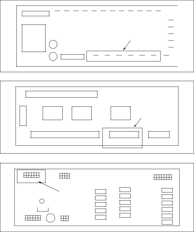
PowerFlex 40 and 400 Drive Control Logic
Computer Output Boards
Connections identified on these figures set speed and direction of the drive.
V-COMPUTER OUTPUT BOARD
X - fmr |
|
|
Drive Control |
|
||
|
|
Connections |
|
|||
|
|
|
|
|
||
|
COM |
RL |
RM |
RH |
STR |
STF |
P/N F370314 |
V-Computer Output Board |
|
|
|
|
|
U135ME3A
Figure 12
WE-6 INTERFACE BOARD
|
Terminals 1 thru 16 |
J7A |
|
J8 |
|
|
|
Ribbon |
|
|
Drive Control |
|
|
Connections |
|
|
|
|
|
J3B |
Terminals 17 thru 29 |
J2A |
J1 |
P/N F370577 WE-6 Output Board |
|
30 31 32 33 34 35 |
|
|
|
||
U136ME3A
Figure 13
EDC OUTPUT BOARD |
|
|
||
1 |
|
6 |
|
|
7 |
H2 |
12 |
H4 |
H5 |
|
|
|||
|
|
|
||
|
|
|
Drive |
|
|
|
|
Control |
|
|
|
|
Connections |
|
|
H1 |
|
H3 |
|
P/N: 370433 EDC Output Board |
|
|
||
|
|
|
|
U148ME3A |
Figure 14
20 |
© Copyright, Alliance Laundry Systems LLC – DO NOT COPY or TRANSMIT |
F232120 |
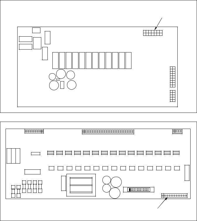
PowerFlex 40 and 400 Drive Control Logic
UNILINC, QUANTUM, GALAXY AND UNIMAC SOFTWARE OUTPUT BOARD |
Drive |
|
Harness |
|
Connection |
|
H13 |
16 |
9 |
8 |
1 |
P/N: F8108001 UniLinc Output Board |
|
|
PHM738N |
Figure 15
A AND B-CONTROL OUTPUT BOARD |
|
Drive Harness |
PHM776N |
Connection J11 |
|
|
PHM776N |
Figure 16 |
|
F232120 |
© Copyright, Alliance Laundry Systems LLC – DO NOT COPY or TRANSMIT |
21 |
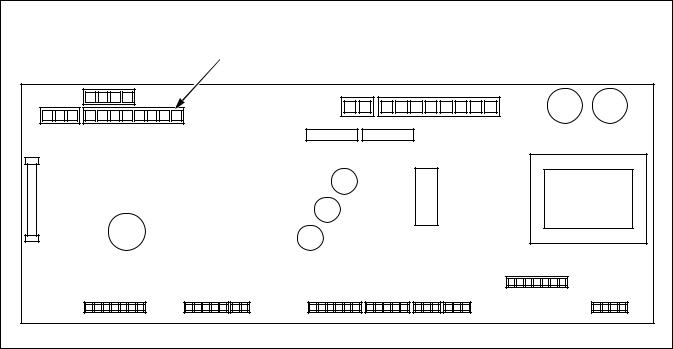
PowerFlex 40 and 400 Drive Control Logic
PS40 CONTROL OUTPUT BOARD |
Drive Harness |
Connection J11 |
PHM777N |
Figure 17 |
22 |
© Copyright, Alliance Laundry Systems LLC – DO NOT COPY or TRANSMIT |
F232120 |
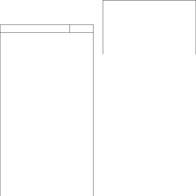
Control Wire
During troubleshooting, if the wire path between the control board and the drive is uncertain, refer to Table 15 for wire connection numbers.
Control Wire Connection Reference Table.
Output Board Terminal
V-Control F370314, F8206501 and F370447-6, etc.
STF |
02 |
|
|
STR |
03 |
|
|
RH |
07 |
|
|
RM |
06 |
|
|
RL |
05 |
|
|
COM |
04 |
|
|
WE-6 Interface Board P/N: F370577, F0370446-xx |
|
|
|
J2A-30 |
04 |
|
|
J2A-31 |
06 |
|
|
J2A-32 |
02 |
|
|
J2A-33 |
07 |
|
|
J2A-34 |
05 |
|
|
J2A-35 |
03 |
|
|
EDC – Output Board P/N: F370433 |
|
|
|
H2-7 |
07 |
|
|
H2-8 |
06 |
|
|
H2-9 |
05 |
|
|
H2-10 |
04 |
|
|
H2-11 |
03 |
|
|
H2-12 |
02 |
|
|
Table 15 (continued) |
|
PowerFlex 40 and 400 Drive Control Logic
Table 15 (continued)
UniLinc Control– Output Board F8108001
H13-2 |
04 |
|
|
H13-3 |
07 |
|
|
H13-4 |
06 |
|
|
H13-5 |
05 |
|
|
H13-6 |
03 |
|
|
H13-7 |
02 |
|
|
|
|
Output Board Terminal |
|
|
|
A and B-Control P/N: F0370448xx |
|
|
|
J11-1-8/STF |
02 |
|
|
J11-1-7/STR |
03 |
|
|
J11-1-6/RH |
07 |
|
|
J11-1-5/RM |
06 |
|
|
J11-1-4/RL |
03 |
|
|
J11-1-3/COM |
04 |
|
|
PS40 Main Board P/N: C000281 |
|
|
|
C12 OV, R-, L- |
01, 04, 14 |
|
|
C12 0-10v |
13 |
|
|
C12 R+ |
02 |
|
|
C12 L+ |
03 |
|
|
Jumper |
N/A |
|
|
Table 15 |
|
F232120 |
© Copyright, Alliance Laundry Systems LLC – DO NOT COPY or TRANSMIT |
23 |
PowerFlex 40 and 400 Drive Control Logic
PowerFlex Drive Parameters
PowerFlex 40 |
PowerFlex 400 Parameter Group |
Parameter |
|
|
Parameter |
Function |
|||
Group and |
and Number |
Description |
||
|
||||
Number |
|
|
|
|
|
|
|
|
|
d001 |
b001 |
Output |
Displays instantaneous output frequency |
|
|
|
Frequency |
(in Hz). |
|
|
|
|
|
|
d002 |
b002 |
Command |
Displays command output frequency (in |
|
|
|
Frequency |
Hz). |
|
|
|
|
|
|
d003 |
b003 |
Output Current |
Displays output current (in Amps). |
|
|
|
|
|
|
d004 |
b004 |
Output Voltage |
Displays output voltage (in VAC). |
|
|
|
|
|
|
d005 |
b005 |
DC Bus Voltage |
Displays DC Bus capacitor voltage (in |
|
|
|
|
VDC). |
|
|
|
|
|
|
d006 |
b006 |
Drive Status |
Read from left to right, the four bits |
|
|
|
|
indicate the drive's condition |
|
|
|
|
(decelerating, accelerating, forward and |
|
|
|
|
running). “0” = false and “1” = true |
|
|
|
|
|
|
d007 |
d307 |
Fault 1 Code |
Memory location for the most recent |
|
|
|
|
fault. Refer to Table 20 for a list of most |
|
|
|
|
fault codes. Repetitive faults are stored |
|
|
|
|
only once. |
|
|
|
|
|
|
d008 |
d308 |
Fault 2 Code |
Memory location for the 2nd most recent |
|
|
|
|
fault. Refer to Table 20 for a list of most |
|
|
|
|
fault codes. Repetitive faults are stored |
|
|
|
|
only once. |
|
|
|
|
|
|
d009 |
d309 |
Fault 3 Code |
Memory location for the 3rd most recent |
|
|
|
|
fault. Refer to Table 20 for a list of most |
|
|
|
|
fault codes. Repetitive faults are stored |
|
|
|
|
only once. |
|
|
|
|
|
|
d010 |
b008 |
Process Display |
Not applicable to Alliance Laundry |
|
|
|
|
Systems’ equipment. Refer to the |
|
|
|
|
manual supplied with the PowerFlex |
|
|
|
|
drive for detailed information. |
|
|
|
|
|
|
d012 |
d301 |
Control Source |
Read from left to right, the digits |
|
|
|
|
indicate the active source of the Speed |
|
|
|
|
Reference (P038) and Start Source |
|
|
|
|
(P036) command. |
|
|
|
|
|
|
d013 |
d302 |
Control Input |
Refer to Table 8 through Table 14 for |
|
|
|
Status |
Control Status Input diagnostics. |
|
|
|
|
|
|
d014 |
d302 |
Digital Input |
Refer to Table 8 through Table 14 for |
|
|
|
Status |
Digital Input Status diagnostics. |
|
|
|
|
|
|
d015 |
d303 |
Communication |
Not applicable to Alliance Laundry |
|
|
|
Status |
Systems' equipment. Refer to the manual |
|
|
|
|
supplied with the PowerFlex drive for |
|
|
|
|
detailed information. |
|
|
|
|
|
|
|
Table 16 (continued) |
|
||
24 |
© Copyright, Alliance Laundry Systems LLC – DO NOT COPY or TRANSMIT |
F232120 |
|
|
PowerFlex 40 and 400 Drive Control Logic |
||
|
Table 16 (continued) |
|
||
|
|
|
|
|
PowerFlex 40 |
PowerFlex 400 Parameter Group |
Parameter |
|
|
Parameter |
Function |
|||
Group and |
and Number |
Description |
||
|
||||
Number |
|
|
|
|
|
|
|
|
|
d016 |
d320 |
Control |
Displays the AC drive's firmware |
|
|
|
Firmware |
version. For PowerFlex 40 drives, this |
|
|
|
Version |
will be 70.xx, 80.xx or 90.xx. For |
|
|
|
|
PowerFlex 400 drives, this will be 14.01. |
|
|
|
|
|
|
d017 |
d321 |
Drive Type |
Displays the numeric code of the drive's |
|
|
|
|
rating (e.g., 4508 = 5hp 200V drive) |
|
|
|
|
|
|
d018 |
b012 |
Elapsed Run |
Displays the accumulated time the drive |
|
|
|
Time |
has output power. The display is in 10- |
|
|
|
|
hour increments (e.g., a display of 1 |
|
|
|
|
represents a value of 10 hours). |
|
|
|
|
|
|
d019 |
d319 |
Testpoint Data |
Displays a hexadecimal value of the |
|
|
|
|
“Testpoint Selection” in parameter |
|
|
|
|
A102. |
|
|
|
|
|
|
d020 |
d305 |
Analog In |
Displays the value (in percentage) of the |
|
|
|
(0-10V) |
voltage at terminal 13(e.g., |
|
|
|
|
100.0%=10V) |
|
|
|
|
|
|
d021 |
d306 |
Analog In |
Displays the value (in percentage) of the |
|
|
|
(4-20mA) |
current at terminal 15 (e.g., 0.0%=4mA; |
|
|
|
|
100.0%=20mA) |
|
|
|
|
|
|
d022 |
b010 |
Output Power |
Displays the kilowatts present at |
|
|
|
|
terminals U, V and W (in kW). |
|
|
|
|
|
|
d023 |
d318 |
Output Power |
Displays the angle in electrical degrees |
|
|
|
Factor |
between the motor voltage and the motor |
|
|
|
|
current. |
|
|
|
|
|
|
d024 |
b014 |
Drive |
Displays the present operating |
|
|
|
Temperature |
temperature (in Celsius) of the drive's |
|
|
|
|
internal power devices. Refer to Fault |
|
|
|
|
008 in Table 20. |
|
|
|
|
|
|
d025 |
N/A |
Counter Status |
Not applicable to Alliance Laundry |
|
|
|
|
Systems' equipment. Refer to the manual |
|
|
|
|
supplied with the PowerFlex drive for |
|
|
|
|
detailed information. |
|
|
|
|
|
|
d026 |
N/A |
Timer Status |
Not applicable to Alliance Laundry |
|
|
|
|
Systems' equipment. Refer to the manual |
|
|
|
|
supplied with the PowerFlex drive for |
|
|
|
|
detailed information. |
|
|
|
|
|
|
d028 |
N/A |
Step Logic |
Not applicable to Alliance Laundry |
|
|
|
Status |
Systems' equipment. Refer to the manual |
|
|
|
|
supplied with the PowerFlex drive for |
|
|
|
|
detailed information. |
|
|
|
|
|
|
|
Table 16 (continued) |
|
||
F232120 |
© Copyright, Alliance Laundry Systems LLC – DO NOT COPY or TRANSMIT |
25 |
PowerFlex 40 and 400 Drive Control Logic
Table 16 (continued)
PowerFlex 40 |
PowerFlex 400 Parameter Group |
Parameter |
|
|
Parameter |
Function |
|||
Group and |
and Number |
Description |
||
|
||||
Number |
|
|
|
|
|
|
|
|
|
d029 |
b013 |
Torque Current |
Displays the present value of the motor's |
|
|
|
|
torque current (in Amps). |
|
|
|
|
|
|
d030 |
N/A |
OL Level |
Displays the real-time motor overload |
|
|
|
|
progression (100% = F007 Fault). |
|
|
|
|
|
|
P041 |
P041 |
Reset to Defaults |
NOTE: This will reset the drive's |
|
|
|
|
parameters back to the factory-default |
|
|
|
|
values, requiring the AC drive to be re- |
|
|
|
|
programmed. This will not reset A193. |
|
|
|
|
(0 = Not Active; 1 = Reset - Induces |
|
|
|
|
Fault F048). |
|
|
|
|
|
|
A101 |
A198 |
Parameter Lock |
Allows parameter modification. |
|
|
|
|
0 = Parameters Unlocked |
|
|
|
|
1= Parameters Locked |
|
|
|
|
See also parameters A192 and A193. |
|
|
|
|
|
|
A152 |
N/A |
Limited |
Displays the maximum allowable |
|
|
|
Frequency |
frequency (in Hz) based on DC Bus |
|
|
|
|
voltage. The drive output frequency may |
|
|
|
|
be limited due to low input voltage |
|
|
|
|
conditions to alleviate potential motor |
|
|
|
|
stalling. |
|
|
|
|
|
|
A164 |
R261 |
Balance State |
Displays the balance detection algorithm |
|
|
|
|
progression (See A187 and A188). (0 = |
|
|
|
|
Algorithm not active; 1 = programmed |
|
|
|
|
pause time; 2 = programmed sample |
|
|
|
|
time; 3 = programmed filter time; 4 = |
|
|
|
|
result obtained) |
|
|
|
|
|
|
A187 |
N/A |
SmartSpin |
Displays the commanded SmartSpin |
|
|
|
Frequency |
frequency (in Hz) as determined from |
|
|
|
|
Balance Result A188. |
|
|
|
|
|
|
A188 |
R285 |
Balance Result |
Displays the numeric value indicating |
|
|
|
|
severity of load imbalance. A balance |
|
|
|
|
result value will be displayed only when |
|
|
|
|
A164 = 4, otherwise the display will be |
|
|
|
|
0. |
|
|
|
|
|
|
A192 |
N/A |
Parameter |
Displays the numeric code culminating |
|
|
|
CRC-16 |
from the value of all of the parameters. |
|
|
|
|
This is intended as a quick reference and |
|
|
|
|
is used to validate the parameter settings |
|
|
|
|
for a specific application. |
|
|
|
|
|
|
|
Table 16 (continued) |
|
||
26 |
© Copyright, Alliance Laundry Systems LLC – DO NOT COPY or TRANSMIT |
F232120 |

|
|
PowerFlex 40 and 400 Drive Control Logic |
||
|
Table 16 (continued) |
|
||
|
|
|
|
|
PowerFlex 40 |
PowerFlex 400 Parameter Group |
Parameter |
|
|
Parameter |
Function |
|||
Group and |
and Number |
Description |
||
|
||||
Number |
|
|
|
|
|
|
|
|
|
A193 |
N/A |
Counter |
This counter will increment each time |
|
|
|
|
parameter A192 changes. This is |
|
|
|
|
intended as a quick reference to show if |
|
|
|
|
any parameter has been changed after |
|
|
|
|
factory programming, even if a |
|
|
|
|
parameter was changed and then |
|
|
|
|
restored to the ALS-specified value. |
|
NOTE: The above parameters and descriptions are based on firmware version 90.06 and may differ or be missing from earlier versions of PowerFlex drive firmware. Refer to parameter d016 for the firmware's version.
NOTE: All PowerFlex drives used in Alliance Laundry Systems' equipment are custom-developed with unique features and parameters. Parameter information provided within the Allen-Bradley PowerFlex series AC drive manual will differ and may not be relevant.
Table 16
F232120 |
© Copyright, Alliance Laundry Systems LLC – DO NOT COPY or TRANSMIT |
27 |
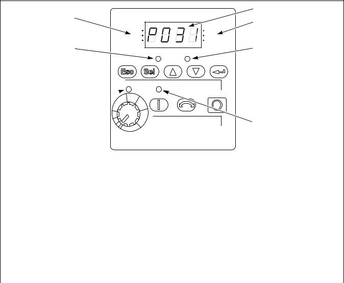
PowerFlex 40 and 400 Drive Control Logic
AC Drive Diagnostics/Parameter Viewing
PowerFlex Integrated Keypad
The PowerFlex series AC drives have an integral keypad that can be used for viewing and editing parameter values. No external parameter unit is required, however an external hand-held parameter unit is available (22-HIM-A3) that can provide a userfriendly method of viewing and editing parameter values in hard-to-access locations.
Integral Keypad
The integral keypad displays several main menu group selections such as “d”, “P”, and “A” as described below. Within the Display Group is a fault storage buffer that stores the last three AC drive fault codes. Refer to the Fault Display and Troubleshooting Information Section for more information.
1
7 |
2 |
|
|
RUN |
VOLTS |
FWD |
AMPS |
REV |
HERTZ |
6 |
3 |
PROGRAM |
FAULT |
5
 4
4
|
|
|
POWERFLEX LED DISPLAYS |
|
|
|
|
|
PHM640N |
|
|
|
|
|
Number |
LED |
LED State |
|
Description |
1 |
Display |
Steady Red |
|
Indicates parameter number, parameter value, or fault code. |
|
Flashing Red |
|
Single digit flashing indicates that digit can be edited. All digits flashing |
|
|
|
|
|
indicates a fault condition. See table below. |
2 |
Displayed Units |
Steady Red |
|
Indicates the units of the parameter value being displayed. |
3 |
Fault Status |
Flashing Red |
|
Indicates drive is faulted. |
4 |
Start Key Status |
Steady Green |
|
Indicates Start key on Integral Keypad is active. The Reverse key is also |
|
|
|
active unless disabled by A095 (Reverse Disable). |
|
|
|
|
|
|
5 |
Pot Status |
Steady Green |
|
Indicates potentiometer on Integral Keypad is active. |
6 |
Program Status |
Steady Red |
|
Indicates parameter value can be changed. |
|
Run/Direction |
Steady Red |
|
Indicates drive is running and commanded motor direction. |
7 |
Status |
|
|
|
Flashing Red |
|
Drive has been commanded to change direction. Indicates actual motor |
||
|
|
|
|
direction while decelerating to zero. |
|
|
|
|
Figure 18 |
28 |
© Copyright, Alliance Laundry Systems LLC – DO NOT COPY or TRANSMIT |
F232120 |
 Loading...