


 Loading...
OmniSwitch® 6800 Series
Getting Started Guide
060195-10, Rev. D
June 2007

Warning. Only personnel knowledgeable in basic electrical and mechanical procedures should install or maintain this equipment.
Lithium Batteries Caution. There is a danger of explosion if the Lithium battery in your chassis is incorrectly replaced. Replace the battery only with the same or equivalent type of battery recommended by the manufacturer. Dispose of used batteries according to the manufacturer’s instructions. The manufacturer’s instructions are as follows:
Return the module with the Lithium battery to Alcatel-Lucent. The Lithium battery will be replaced at Alcatel-Lucent’s factory.
The features and specifications described in this guide are subject to change without notice.
Copyright © 2007 by Alcatel-Lucent. All rights reserved. This document may not be reproduced in whole or in part without the express written permission of Alcatel-Lucent.
Alcatel-Lucent® and the Alcatel-Lucent logo are registered trademarks of Alcatel-Lucent. Xylan®, OmniSwitch®, OmniStack®, and Alcatel-Lucent OmniVista® are registered trademarks of Alcatel-Lucent.
OmniAccess™, Omni Switch/Router™, PolicyView™, RouterView™, SwitchManager™, VoiceView™, WebView™, X-Cell™, X-Vision™, and the Xylan logo are trademarks of Alcatel-Lucent.
This OmniSwitch product contains components which may be covered by one or more of the following U.S. Patents:
• U.S. Patent No. 6,339,830 |
|
|
|
• U.S. Patent No. 6,070,243 |
|
|
|
• U.S. Patent No. 6,061,368 |
|
|
|
• U.S. Patent No. 5,394,402 |
|
|
|
• U.S. Patent No. 6,047,024 |
|
|
|
• U.S. Patent No. 6,314,106 |
Alcatel-Lucent |
||
• U.S. Patent No. 6,542,507 |
|||
26801 West Agoura Road |
|||
|
Calabasas, CA 91301 |
||
|
(818) 880-3500 FAX (818) |
880-3505 |
|
|
US Customer Support: (800) |
995-2696 |
|
|
International Customer Support: (818) |
878-4507 |
|
|
Internet: service.esd.alcatel-lucent.com |
||

Table of Contents
OmniSwitch 6800 Series. . . . . . . . . . . . . . 1
Related Documentation . . . . . . . . . . . . . . . . . . . . . . . . . . 2
Installing the Hardware . . . . . . . . . . . . . . . 3
Items Required . . . . . . . . . . . . . . . . . . . . . . . . . . . . . 3
Site Preparation . . . . . . . . . . . . . . . . . . . . . . . . . . . . 3 Environmental Requirements . . . . . . . . . . . . . . . 3 Electrical Requirements . . . . . . . . . . . . . . . . . . . 3 Weight Considerations . . . . . . . . . . . . . . . . . . . . 3
Items Included . . . . . . . . . . . . . . . . . . . . . . . . . . . . . 4
Unpacking and Initial Setup . . . . . . . . . . . . . . . . . . . 4 Unpacking the Chassis . . . . . . . . . . . . . . . . . . . . 4 Recommendations . . . . . . . . . . . . . . . . . . . . 4 Instructions . . . . . . . . . . . . . . . . . . . . . . . . . 4
Setting Up the Switch . . . . . . . . . . . . . . . . . . . . . . . . 5 Airflow Considerations . . . . . . . . . . . . . . . . . . . . 5 Installation Options . . . . . . . . . . . . . . . . . . . . . . . 6 Installing the Switch on a Tabletop or Bench . . . 6 Tabletop Mounting Steps . . . . . . . . . . . . . . . 6 Rack-Mounting the Switch . . . . . . . . . . . . . . . . . 7 Rack Mounting Steps . . . . . . . . . . . . . . . . . . 7
Installing Combo Port SFPs . . . . . . . . . . . . . . . . . . . 9 Installing Backup Power Supply Components . . . . . 9
Connections and Cabling . . . . . . . . . . . . . 10
Connecting the Serial Cable . . . . . . . . . . . . . . . . . . 10
Serial Connection Default Settings . . . . . . . . . . . . . 10
Booting OmniSwitch 6800 Series
Switches. . . . . . . . . . . . . . . . . . . . . . . . . . . . . . . . . . . . 11
Booting a Standalone Switch . . . . . . . . . . . . . . . . . 11
Your First Login Session . . . . . . . . . . . . . . . 12
Logging In to the Switch . . . . . . . . . . . . . . . . . . . . . 12
Assigning an IP Address to the Switch . . . . . . . . . . 13
Unlocking Session Types . . . . . . . . . . . . . . . . . . . . 14
Changing the Login Password . . . . . . . . . . . . . . . . 15
Setting the System Time Zone . . . . . . . . . . . . . . . . 15
Setting the Date and Time . . . . . . . . . . . . . . . . . . . . 16
Setting Optional System Information . . . . . . . . . . . 16
Specifying an Administrative Contact . . . . . . .16
Specifying a System Name . . . . . . . . . . . . . . . .17
Specifying the Switch’s Location . . . . . . . . . . .17
Viewing and Saving Changes . . . . . . . . . . . . . . . . . 17
June 2007 |
iii |
Files and Directories. . . . . . . . . . . . . . . . . . . . 18 Boot and Image Files . . . . . . . . . . . . . . . . . . . . . . . . . . . 18 boot.params File . . . . . . . . . . . . . . . . . . . . . . . . . . . 18 boot.cfg File . . . . . . . . . . . . . . . . . . . . . . . . . . . . . . 18 boot.slot.cfg File . . . . . . . . . . . . . . . . . . . . . . . . . . . 19 Image Files . . . . . . . . . . . . . . . . . . . . . . . . . . . . . . . 19
Working and Certified Directories . . . . . . . . . . . . . . . . 20 Working Directory . . . . . . . . . . . . . . . . . . . . . . 20 Certified Directory . . . . . . . . . . . . . . . . . . . . . . 21
Using WebView . . . . . . . . . . . . . . . . . . . . . . . . . 24 Browser Compatibility . . . . . . . . . . . . . . . . . . . . . . 24 Logging In to WebView . . . . . . . . . . . . . . . . . . . . . 24 Navigating WebView . . . . . . . . . . . . . . . . . . . . . . . 25 Online Help . . . . . . . . . . . . . . . . . . . . . . . . . . . . . . 27 Additional Information . . . . . . . . . . . . . . . . . . . . . . 27 Troubleshooting . . . . . . . . . . . . . . . . . . . . . . . . . . . 28
iv |
June 2007 |

OmniSwitch 6800 Series
OmniSwitch 6800-24
OmniSwitch 6800-48
OmniSwitch 6800-U24
The OmniSwitch 6800 Series is an advanced fixed configuration family of Ethernet switches. These switches provide wire rate Layer 2 forwarding and Layer 3 routing with advanced services.
They are fixed configuration, triple-speed (10/100/1000) switches that provide increased network performance, improved application response times, secure the LAN, and enhance user productivity by maximizing mobility, network capacity, and services over existing category 5/5E/6 cabling.
Refer to the User Manual CD for additional hardware and software OmniSwitch documentation.
OmniSwitch 6800-24L
OmniSwitch 6800-48L
June 2007 |
OmniSwitch 6800 Series 1 |
Related Documentation
The following are the titles and descriptions of all the OmniSwitch 6800 Series user documentation included in the User Manual CD:
• OmniSwitch 6800 Series Getting Started Guide
Describes the hardware and software procedures for getting an OmniSwitch 6800 Series switch up and running. Also provides information on fundamental aspects of OmniSwitch hardware components and software architecture.
• OmniSwitch 6800 Series Hardware Users Guide
Complete technical specifications and procedures for all OmniSwitch 6800 Series hardware, including chassis, power supplies, fans, combo ports, stacking procedures, optional backup power supplies, etc.
• OmniSwitch CLI Reference Guide
Complete reference to all CLI commands supported on the OmniSwitch 6800 Series. Includes syntax definitions, default values, examples, usage guidelines, and CLI-to-MIB variable mappings.
•OmniSwitch 6800/6850/9000 Switch Management Guide
Includes procedures for readying a switch for integration into a network. Topics include the software
directory architecture, image rollback protections, authenticated switch access, managing switch files, system configuration, using SNMP, and using web management software (WebView).
•OmniSwitch 6800/6850/9000 Network Configuration Guide
Includes network configuration procedures and descriptive information on all the major software features and protocols included in the base software package. Chapters cover Layer 2 information (Ethernet and VLAN configuration), Layer 3 information (static routes), security options (authenticated VLANs), Quality of Service (QoS), and link aggregation.
•OmniSwitch 6800/6850/9000 Advanced Routing Configuration Guide
Includes network configuration procedures and descriptive information on all the software features and protocols included in the advanced routing software package. Chapters cover multicast routing (DVMRP and PIM-SM) and OSPF.
•OmniSwitch Transceivers Guide
Includes information on Small Form Factor Pluggable (SFPs) and 10 Gbps Small Form Factor Pluggables (XFPs) transceivers.
2 OmniSwitch 6800 Series |
June 2007 |

Installing the Hardware
Items Required
In addition to the materials and components provided in the OmniSwitch 6800 Series shipment, you must provide the following items in order to complete this installation:
•Grounding wrist strap
•Phillips screwdriver
•Serial cable
•Rack mount screws, if applicable
Site Preparation
Environmental Requirements
OmniSwitch 6800 Series switches have the following environmental and airflow requirements:
•The installation site must maintain a temperature between 0° and 45° Celsius (32° and 122° Fahrenheit) and not exceed 95 percent maximum humidity (noncondensing) at any time.
•Be sure to allow adequate room for proper air ventilation and access at the front, back, and sides of the switch. No clearance is necessary at the top or bottom of the chassis. Refer to page 5 for minimum clearance requirements.
Electrical Requirements
OmniSwitch 6800 Series switches have the following general electrical requirements:
•Each switch requires one grounded AC power source.
•Grounded AC power source must be 110V for North American installations (220V international).
•Each supplied AC power cord is approximately 2 meters (6.5 feet) long. Do not use extension cords.
Weight Considerations
A single OS6800 weighs approximately 14 lbs. (6.30 Kg). A stack of eight OS6800 switches weighs approximately 111 lbs (50.4 Kgs).
June 2007 |
Installing the Hardware 3 |
Items Included
Your OmniSwitch 6800 Series switch order includes the following items:
•OmniSwitch chassis
•Rack mount flanges with attachment screws (rack mount flanges may be pre-installed on some orders)
•Power cord (country-specific)
•Documentation CD containing a complete set of user guides for the switch and switch software. Refer to “Related Documentation” on page 2 for a complete list of included documentation.
Depending on the items ordered for your specific network requirements, the following optional items may also be included:
•Stacking cables (per order)
•SFPs (per order)
•10 Gigabit XFP connectors (per order)
•Backup power supply components and cables (per order)
Unpacking and Initial Setup
Unpacking the Chassis
To protect your OmniSwitch chassis and hardware components from electrostatic discharge (ESD) and physical damage, read all unpacking recommendations and instructions carefully before beginning.
Recommendations
•Unpack your OmniSwitch chassis as close as possible to the location where it will be installed.
•Depending on your order, Small Form-Factor Pluggables (SFPs), stacking cables, and backup power supply components may be packaged separately. In order to greatly reduce exposure to electrostatic discharge (ESD) and physical damage, do not unpack these items until they are ready to be installed.
Instructions
1Carefully cut the tape along the seam at the top of the box containing the chassis.
2Lift the box’s top flaps. Remove any smaller boxes or pouches that are enclosed and set them aside.
3Lift the chassis out of the packaging.
4Carefully remove any foam pads and protective plastic from the switch chassis.
4 Installing the Hardware |
June 2007 |
Note. Alcatel-Lucent provides factory-installed blank cover plates for empty backup power supply or 10 Gigabit expansion module bays. Do not remove these cover plates unless a backup power supply or expansion module is to be installed immediately at the corresponding bay.
5If you are installing multiple switches in a stacked configuration, repeat steps 1 through 4 for the remaining switches that will make up the stack.
6Once all OmniSwitch 6800 Series switches have been removed from their packaging, continue to “Setting Up the Switch.”
Setting Up the Switch
Note. Due to their airflow and access requirements, OmniSwitch 6800 Series switches cannot be wallmounted.
Airflow Considerations
Be sure that your switch is placed in a well-ventilated, staticfree environment. Always allow adequate clearance at the front, rear, and sides of the switch.
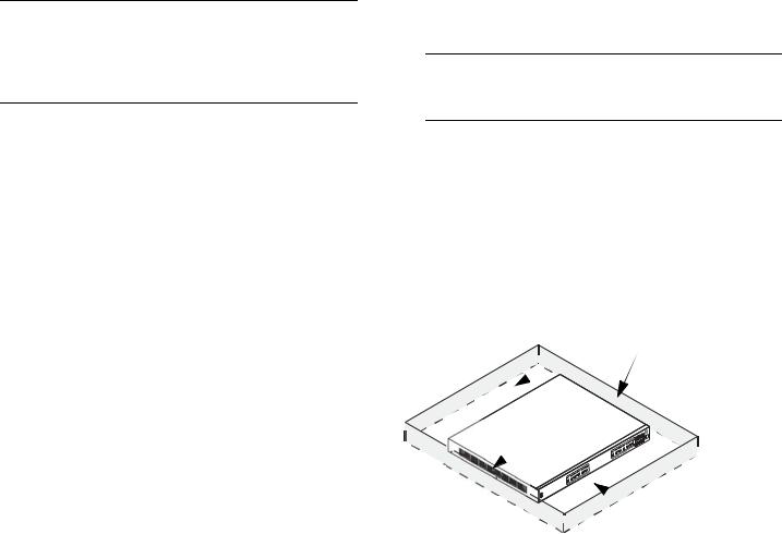
The following diagram shows recommended minimum clearances for adequate chassis airflow and access to components at the rear of the chassis:
Rear. 5 inches minimum at rear of chassis.
 Sides. 2 inches minimum at left and right sides for chassis airflow.
 Front. 6 inches minimum at front of chassis for cable access and LED visibility.
Chassis Top View
June 2007 |
Installing the Hardware 5 |

Never obstruct the air vents located at the left and right sides of the chassis.
Note. Clearance is not required at the top and bottom of the chassis. For detailed chassis airflow diagrams, refer to the OmniSwitch 6800 Series Hardware Users Guide.
Installation Options
There are two ways in which the OmniSwitch 6800 Series switches can be installed:
•Tabletop installation
•Rack-mount installation
For information on setting up a switch as a tabletop unit, refer to “Installing the Switch on a Tabletop or Bench.” For information on rack-mounting the switch, refer to “Rack-Mounting the Switch” on page 7.
Installing the Switch on a Tabletop or Bench
OmniSwitch 6800 Series switches can be installed freestanding as tabletop units. Place your switch in a stable, flat, staticfree surface.
Note. OmniSwitch 6800 Series switches must be placed “right side up.” Never attempt to operate a switch positioned on its side.
Tabletop Mounting Steps
To install the switch as a tabletop unit, follow the steps below:
1Position the chassis on the table or bench where it is to be installed.
2Be sure that adequate clearance has been provided for chassis airflow and access to the front, back, and sides of the switch. For recommended clearances, refer to page 5. Also, be sure that you have placed the chassis within reach of all required AC power sources.
If you are placing multiple switches in a stacked configuration, carefully stack the remaining switches, one on top of the other. Up to eight switches may be stacked to form a single virtual chassis. Be sure to maintain adequate clearance at the front, rear, left, and right side of all switches (see page 5). Also, be sure that you have placed all switches in the stack within reach of required AC power sources.
Note. If you are installing a single (i.e., standalone) switch, continue to “Connections and Cabling” on page 10 for additional setup procedures.
6 Installing the Hardware |
June 2007 |
Loading...