


ASM 142 / 142 D
ASM GRAPH / GRAPH D / GRAPH D+
HELIUM LEAK DETECTOR
User’s Manual

Alcatel Vacuum Technology, as part of the AlcatelLucent Group, has been supplying vacuum pumps, helium and hydrogen leak detection systems, plasma sensors, vacuum measurement for several years.
Thanks to its complete range of products, the company has become an essential player in multiple applications : instrumentation, Research & Developement, industry and semiconductors.
Alcatel Vacuum Technology has launched Adixen, its new brand name, in recognition of the company’s international standing in vacuum position.
With both ISO 9001 and 14001 certifications, the French company is an acknowlegded expert in service and support, and Adixen products have the highest quality and environmental standards.
With 45 years of experience, AVT today has a worldwide presence, through its international network that includes a whole host of experienced subsidiaries, distributors and agents.
The first step was the founding of Alcatel Vacuum Products (HinghamMA) in the United States, thirty years ago, reinforced today by 2 others US subsidiaries in Fremont (CA) and Tempe (AZ).
In Europe, AVTF-France headquarters and its subsidiaries, Alcatel Hochvakuumtechnik (Germany), Alcatel Vacuum Technology UK (Scotland), Alcatel Vacuum Technology Benelux (Netherlands), Alcatel Vacuum Systems (Italy) and more recently Adixen Sensistor AB in Sweden (in 2007) form the foundation for the European partner network.
In Asia, our presence started in 1993 with Alcatel Vacuum Technology (Japan), and has been strengthened with Alcatel Vacuum Technology Korea (in 1995), Alcatel Vacuum Technology Taiwan (in 2001), Alcatel Vacuum Technology Singapore, Alcatel Vacuum Technology Shanghai (China) (in 2004).
This organization is rounded off by more than 40 represensatives based in a variety of continents.
Thus, whatever the circumstances, the users of Adixen products can always rely on quick support of our specialists in Vacuum Technology.
02834 - Edition 04 - Feb 08
Gb

A very wide range of helium leak detectors
GB 00204 - Edition 05 - September 06
Dear customer,
You have just bought an Adixen leak detector.
We would like to thank you and we are proud to count you among our customers. This product is a result of the experience acquired over 35 years by Alcatel Vacuum Technology France in vacuum and leak detection technology.
The applications of helium leak testing are extremely diversified ranging from high-tech installation maintenance to highspeed testing of industrial products.
Each product of the Adixen detector range is designed to meet the specific needs of each application:
•portability,
•high sensitivity,
•pumping capacity,
•pumping type,
•automation and integration in an industrial process.
1/2

A very wide range of helium leak detectors
This product complies with the requirements of European Directives, listed in the Declaration of Conformity contained in G100 of this manual. These Directives are amended by Directive 93/68/E.E.C (E.C. Marking).
The Declaration of Conformity and Safety Instructions are available in German, Spanish, Italian, Portuguese, Dutch and Danish languages at the end of this manual.
Copyright/Intellectual property:
The use of Adixen products are subject to copyright and intellectual property rights in force in any jurisdiction.
All rights reserved, including copying this document in whole or any part without prior written authorization from Alcatel Vacuum Technology France.
Specifications and information are subject to change without notice by from Alcatel Vacuum Technology France.
GB 00204 - Edition 05 - September 06
2/2

GB 00205 - Edition 07 - March 09
Manual reference: 107817
edition: 07 - March 2009 Software version:
ASM 142/ASM GRAPH: L0088 v3.1 r.02
ASM 142 D/ASM GRAPH D/ ASM GRAPH D+: L0114 v3.1 r.02
Preliminary
remarks
General contents
ASM 142 - ASM 142 D |
|
ASM GRAPH - ASM GRAPH D |
User’s Manual |
ASM GRAPH D+ |
Throughout this User’s Manual, you could find this type of message “Summary of screen  C 140”: it refers to a specific chapter of the User’s Manual. Please read it for further information.
Chapter A |
|
INTRODUCTION |
|
A 100 - Introduction to the ASM 142 series |
|
|
A 200 - ASM 142 - Detector operating principle |
|
|
A 201 - ASM 142 D - Detector operating principle |
|
|
A 202 - ASM 142 Graph D+ - Detector operating principle |
|
|
A 300 - Analyzer cell operating principle |
|
|
A 400 - Testing methods |
|
|
A 401 - About Helium and Hydrogen |
|
|
A 500 - Operator interface: control panel |
|
|
A 600 - Options |
|
|
A 700 - Accessories |
|
|
A 800 - ASM 142 - Technical characteristics |
|
|
A 801 - ASM 142 D - ASM Graph D+ - Technical characteristics |
|
|
A 900 - Dimensions |
|
|
A 901 - Dimensions ASM Graph D+ |
|
|
|
|
Chapter B |
|
INSTALLATION |
|
B 100 - Safety instructions |
|
|
B 110 - Unpacking - Storage - Transportation |
|
|
B 200 - Neutral gas purge and inlet vent connection |
|
|
B 201 - Neutral gas purge installation (accessory) |
|
|
B 210 - Connecting the detector to the installation |
|
|
B 211 - Connecting the detector to the installation: ASM graph D+ |
|
|
B 300 - Controlling the detector with the I/O |
interface |
|
|
B 310 - Controlling the detector with a PC computer through the RS 232 interface |
|
|
|
B 320 - Connecting the detector directly to a printer or another device |
|
|
|
B 400 - Before starting up the leak detector |
|
|
|
|
|
|
Chapter C |
|
OPERATION |
|
|
C 100 - Factory configuration of the leak detector parameters |
|
|
|
C 110 - Operating principle of the control panel |
|
|
|
C 120 - Setting and maintenance part presentation of the control panel |
|
|
|
C 130 - Access to level 4 - Password |
|
|
|
C 140 - Summary of screens |
|
|
|
C 200 - Starting up / Switching off the leak detector |
|
|
|
C 210 - How to use the leak detector: 2 methods |
|
|
|
C 211 - Operation of the leak detector |
|
|
|
C 300 - Calibration of the leak detector |
|
|
|
C 301 - Basic internal calibration of the leak detector |
|
|
|
C 302 - Advanced internal calibration of the leak detector |
|
|
|
C 303 - External calibration of the leak detector |
|
|
|
C 304 - Correction factor |
|
|
|
C 305 - Calibrated leak values programming |
|
|
|
C 306 - Adaptor for calibrated leak in sniffing mode |
|
|
|
C 400 - Remote control |
|
|
|
C 410 - Headphone and loudspeaker |
|
|
|
C 430 - 3 masses option |
|
|
|
C 440 - Control panel with graphic interface |
|
|
|
C 450 - Long distance sniffer probe and Helium spray gun |
|
|
|
|
|
Alcatel Vacuum Technology France - User’s Manual ASM 142/142 D - ASM GRAPH/GRAPH D/GRAPH D+ |
1/3 |
||

Manual reference: 107817 |
|
General contents |
|
edition: 07 - March 2009 |
|
||
|
|
|
|
Software version: |
|
|
|
ASM 142 - ASM 142 D |
|
||
ASM 142/ASM GRAPH: |
|
||
L0088 v3.1 r.02 |
ASM GRAPH - ASM GRAPH D |
|
|
ASM 142 D/ASM GRAPH D/ |
User’s Manual |
||
ASM GRAPH D+: L0114 v3.1 r.02 |
ASM GRAPH D+ |
||
C 500 - Inlet vent |
|
C 510 |
- Bargraph zoom |
C 520 |
- Audio alarm/Digital voice |
C 530 |
- Cycle end |
C 540 |
- Zero function |
C 550 |
- Memo function |
C 560 |
- Helium pollution prevention |
C 570 |
- Date - Time - Language - Unit |
C 580 |
- Fault / information indicator and display |
Chapter D MAINTENANCE - TROUBLESHOOTING
D 100 |
- Table of preventive maintenance intervals |
D 200 |
- Maintenance message |
D 300 |
- General troubleshooting guide |
D 300/D 400 - General troubleshooting guide/Symptoms description
D 400 - Symptoms description
Chapter E |
|
MAINTENANCE SHEETS |
|
E 100 - Maintenance operations introduction |
|
|
E 110 - ASM 142 / ASM 142 S - Access to internal components |
|
|
E 111 - ASM 142 D - ASM Graph D+ - Access to the internal components |
|
|
E 120 - Sending the leak detection for reparation to a service center |
|
|
E 400 - Basic maintenance of the analyzer cell |
|
|
E 530 - Valves installation and maintenance |
|
|
E 560 - Replacement of the internal calibrated leak |
|
|
E 600 - Remote control |
|
|
E 610 - Long distance sniffer probe and Helium spray gun |
|
|
E 710 - Primary pump maintenance (AMD1) |
|
|
E 730 |
- Starting of the molecular and turbomolecular pumps |
|
E 740 |
- Greasing molecular and turbomolecular pumps |
|
E 750 |
- Primary pump maintenance |
Chapitre F |
|
|
COMPONENTS |
|
F 000 - Spare parts instructions of use |
||
|
F 001 - AVTF Customer Service Offer |
||
|
F 100 - Tools |
|
|
|
F 200 - Monitoring and display |
||
|
F 300 - Power and electrical supply |
||
|
F 400 - Automatic control system and electronic circuits |
||
|
F 500 - Measurement |
||
|
F 600 - ASM 142 |
- Pumping |
|
|
F 600 - ASM 142 |
D - Pumping |
|
|
F 700 - Valves |
|
|
|
F 800 |
- ASM 142 |
- Pipes - Connections - Seals |
|
F 800 |
- ASM 142 |
D - Pipes - Connections - Seals |
|
F 900 |
- Cover |
|
F 1000 - Options - Accessories
F 1100 - Pictures of components
GB 00205 - Edition 07 - March 09
2/3 |
Alcatel Vacuum Technology France - User’s Manual ASM 142/142 D - ASM GRAPH/GRAPH D/GRAPH D+ |

Manual reference: 107817
edition: 07 - March 2009 Software version:
ASM 142/ASM GRAPH: L0088 v3.1 r.02
ASM 142 D/ASM GRAPH D/ ASM GRAPH D+: L0114 v3.1 r.02
General contents
ASM 142 - ASM 142 D |
|
ASM GRAPH - ASM GRAPH D |
User’s Manual |
ASM GRAPH D+ |
Chapter G |
|
|
APPENDIX |
|
G 100 - Declaration of conformity |
||
|
G 200 - ASM 142 |
- Wiring diagrams |
|
|
G 201 - ASM 142 |
D - Wiring diagrams |
|
|
G 300 - Analog output |
||
|
G 400 - Long distance sniffer probe user manual |
||
|
G 500 |
- Helium spray gun user manual |
|
|
G 600 |
- Safety questionnaire |
|
|
G 800 |
- Tools |
|
GB 00205 - Edition 07 - March 09
Indicates a potentially hazardous situation which, if not avoided, could result in property damage.
Indicates a potentially hazardous situation which, if not avoided, could result immoderate or minor injury. It may also be used to alert
CAUTION against unsafe practices.
Indicates a potentially hazardous situation which, if not avoided, could result in death or severe injury.
CAUTION
Indicated an imminently hazardous situation that, if not avoided,
will result in death or severe injury (extreme situations).
WARNING
Alcatel Vacuum Technology France - User’s Manual ASM 142/142 D - ASM GRAPH/GRAPH D/GRAPH D+ |
3/3 |

GB 00206 - Edition 03 - June 08
A |
|
|
Introduction |
||
|
|
|
|
||
ASM 142 - ASM 142 D |
|
|
|||
ASM GRAPH - ASM |
GRAPH D |
||||
ASM GRAPH D+ |
User’s Manual |
||||
|
|||||
Preliminary
remarks
Detailed contents
Throughout this User’s Manual, you could find this type of message “Summary of screen  C 140”: it refers to a specific chapter of the User’s Manual. Please read it for further information.
A 100 |
Introduction to the ASM 142 series |
|
- A new generation of Adixen helium leak detector |
|
|
A 200 |
ASM 142 - Detector operating principle |
|
- Vacuum circuit |
|
- Stand-by mode |
|
- Roughing mode |
|
- Gross leak test mode |
|
- Normal test mode |
|
- Sniffing test mode |
|
|
A 201 |
ASM 142 D - Detector operating principle |
|
- Vacuum circuit |
|
- Stand-by mode |
|
- Roughing mode |
|
- Gross leak test mode |
|
- Normal test mode |
|
- Sniffing test mode |
|
|
A 202 |
ASM 142 Graph D+ - Detector operating principle |
|
- Vacuum circuit |
|
- Stand-by mode |
|
- Roughing mode |
|
- Gross leak test mode |
|
- Normal test mode |
|
- Sniffing test mode |
|
|
A 300 |
Analyzer cell operating principle |
|
- Description |
|
- Design and manufacture |
|
|
A 400 |
Testing methods |
|
- Overview |
|
- Helium concentration and signal displayed |
|
- Spray method (inboard testing) |
|
- Sniffer method (outboard testing) |
|
- Bombing method |
|
|
A 401 |
About Helium and hydrogen |
|
- Helium |
|
- Helium and leak detection: which purity? |
|
- Hydrogen |
|
Operator interface : control panel |
A 500 |
1/2

Introduction
|
ASM 142 - ASM 142 D |
|
|
|
|
ASM GRAPH - ASM |
GRAPH D |
||
A ASM GRAPH D+ |
|
User’s Manual |
||
|
Detailed contents |
|
|
|
|
|
|
|
|
A 600 |
|
|
Options |
|
|
- Which options for which model? |
|
|
|
|
- Metal seals |
|
|
|
|
- Inlet port |
|
|
|
|
- Units |
|
|
|
|
- Languages |
|
|
|
|
- 3 masses |
|
|
|
|
- Automatic test chambers |
|
|
|
|
- Roughing system |
|
|
|
|
- Interface board |
|
|
|
|
- Remote control cable length |
|
|
|
|
- Test of gas line |
|
|
|
|
- Stainless steel cover (UCT) |
|
|
|
|
- Control panel with graphic interface |
|
|
|
|
- Control panel racks |
|
|
|
|
- Sniffing |
|
|
|
|
- Cables lengths |
|
|
|
|
|
|
||
A 700 |
|
|
Accessories |
|
|
- Which accessories for which model? |
|
|
|
|
- Remote control |
|
|
|
|
- Long Distance Sniffer probe |
|
|
|
|
- 10 m/30 feet LDS extension |
|
|
|
|
- Headphone connector |
|
|
|
|
- Transport cart |
|
|
|
|
- Foot pedal for cycle command (1.5 m/5 |
feet) |
||
|
- Calibrated Helium leaks |
|
|
|
|
- Calibration accessory |
|
|
|
|
- Spray probe |
|
|
|
|
- Inlet adaptor |
|
|
|
- Printer
- Inlet filters
- Short distance sniffer probe (to be connected to the inlet part of a leak detector)
-Bombing chamber
-Test chambers
-Neutral gas vent line kit
- 4 swiveling wheels kit (Ø125 mm)
-Covered sniffer probe and remote control kit
-Bottle handle for cart
-Built-in mini-printer
- 2005 IS Pump
-Pressure measurement kit
-Ventilation Kit
-Bottle handle for cart
A 800 |
ASM 142 - Technical characteristics |
|
ASM 142 D - ASM Graph D+ - Technical characteristics |
A 801 |
|
|
Dimensions |
A 900 |
|
|
|
A 901 |
Dimensions - ASM Graph D+ |
GB 00206 - Edition 03 - June 08
2/2
A 100
Introduction to the ASM 142 series
A new generation of Adixen helium leak detector
The ASM 142/142 D/142 S/ASM Graph/ASM Graph D/ ASM Graph D+ are universal helium leak detectors which set new performance standards for multi-purpose unit.
These detectors are the end-result of an innovative engineering approach utilizing the latest electronics technologies and vacuum concepts, which make them a truly universal unit:
Model photographed: ASM 142
GB 00207 - Edition 04 - June 08
|
ASM |
ASM |
ASM |
ASM |
ASM |
ASM |
|
|
|||||||
|
142 |
Graph |
142 D |
Graph D |
142 S |
Graph |
|
|
|
|
|
|
|
D+ |
|
high performances, such as, |
|
|
|
|
|
|
|
a roughing capacity of 7 CFM |
|
|
|
|
|
|
|
(60 l/mn) with a usable helium |
x |
x |
|
|
|
x |
|
sensitivity in the 10-11 atm.cc/ |
|
|
|
|
|
|
|
sec range. |
|
|
|
|
|
|
|
|
|
|
|
|
|
|
|
high performances, such as, |
|
|
|
|
|
|
|
a dry roughing capacity of 0.9 |
|
|
|
|
|
|
|
CFM (1.5 m3/h) with a usable |
|
|
x |
x |
|
x |
|
helium sensitivity in the 10-11 |
|
|
|
|
|
|
|
atm.cc/sec range. |
|
|
|
|
|
|
|
|
|
|
|
|
|
|
|
a usable helium sensitivity |
|
|
|
|
|
|
|
in the |
|
|
|
|
x |
|
|
10-7 atm.cc/sec range (with |
|
|
|
|
|
||
|
|
|
|
|
|
||
auto-zero function). |
|
|
|
|
|
|
|
|
|
|
|
|
|
|
|
comprehensive control panel |
|
|
|
|
|
|
|
with two distinct areas (one |
|
|
|
|
|
|
|
for the operation of the unit, |
x |
x |
x |
x |
x |
x |
|
the other for entering the test |
|
|
|
|
|
|
|
parameters). |
|
|
|
|
|
|
|
|
|
|
|
|
|
|
|
evolved features to assist the |
|
|
|
|
|
|
|
operator in his daily operation |
|
|
|
|
|
|
|
(auto-calibration, auto-zero, |
x |
x |
x |
x |
x |
x |
|
helium signal direct readout, |
|
|
|
|
|
|
|
...). |
|
|
|
|
|
|
|
|
|
|
|
|
|
|
|
very rugged design, based on |
|
|
|
|
|
|
|
field-proven components, which |
x |
x |
x |
x |
x |
x |
|
makes it ideal for any industrial |
|||||||
|
|
|
|
|
|
||
environment. |
|
|
|
|
|
|
|
|
|
|
|
|
|
|
|
various accessories to |
|
|
|
|
|
|
|
reinforce the versatility of the |
x |
x |
x |
x |
x |
x |
|
product (remote control, sniffer |
|||||||
|
|
|
|
|
|
||
probe). |
|
|
|
|
|
|
|
|
|
|
|
|
|
|
|
totally dry leak detector. |
|
|
x |
x |
|
x |
|
|
|
|
|
|
|
|
|
specific to sniffing test mode |
|
|
|
|
|
|
|
applications. |
|
|
|
|
x |
|
|
graphic interface. |
|
x |
|
x |
|
|
We suggest that you read this manual before you start to use your detector to obtain optimum levels of performance and complete satisfaction.
1/1
A 200
ASM 142 detector operating principle
GB 00208 - Edition 03 - June 08
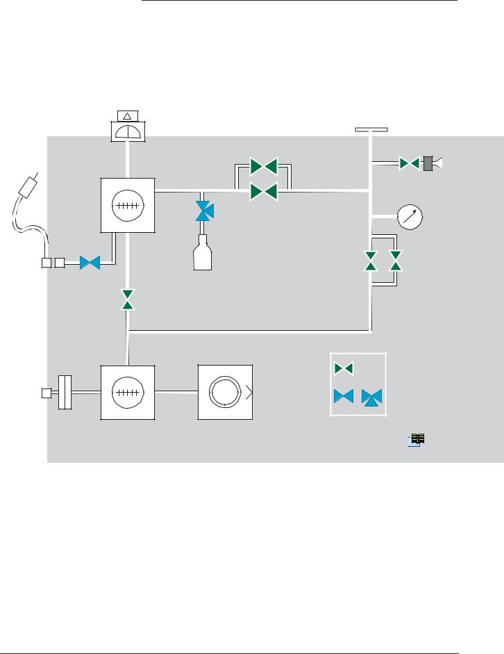
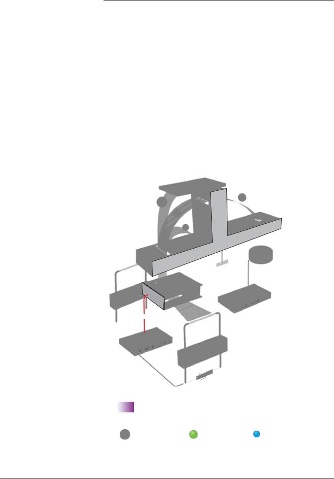
Vacuum circuit
1 |
3 |
|
|
|
|
2 |
|
|
VT3 |
VA1 |
7 |
|
18 |
VT2 |
|
|
VC |
|
|
|
|
|
5 |
|
4 |
VR1 |
VR2 |
8 |
VS |
|
|
 VT1
VT1
Bacosol valve
Minisol valves
15
|
Reference correspondence between valve/vacuum block marks |
E 530 |
||
1 |
Preamplifier |
VA1 |
Inlet vent valve (6 points) |
|
2 |
Analyzer cell |
VR1 |
Roughing valve ( point) |
|
3 |
Detector inlet port |
VR2 |
Roughing valve (2 points) |
|
4 |
Internal calibrated leak |
VT1 |
Exhaust valve (3 points) |
|
5 |
Inlet pressure gauge |
VT2 |
Detection valve (4 points) |
|
7 |
Vent connector |
VT3 |
Detection valve (5 points) |
|
8 |
Long distance sniffer connector |
VS |
Sniffing valve (9 points) |
|
15 |
Roughing primary pump (RVP 20 0) |
VC |
Calibration valve (7 points) |
|
18 |
Detection molecular pump (AMP 007I) |
|
|
|
/4
A 200
ASM 142 detector operating principle
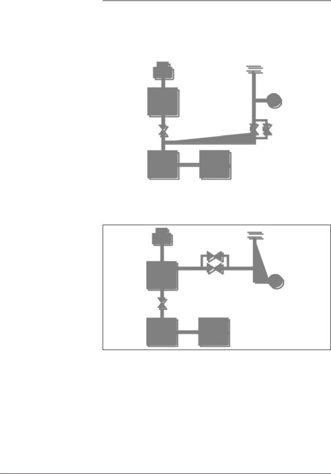
Stand-by mode |
|
|
|
|
|
|
|
|
|
|
|
|
|
1 |
|
|
|
3 |
|
|
|
|
|
|
|||
|
|
|
|
|
|
|
|
|
|
||||
|
|
|
2 |
|
|
|
|
VA1 7 |
|
||||
|
|
|
|
|
|
|
|||||||
|
18 |
|
|
|
|
|
|
||||||
|
|
|
|
|
|
||||||||
|
|
|
|
|
|
||||||||
|
|
|
|
|
|
|
|
|
|
|
|
|
|
|
|
|
|
|
|
|
|
|
|
|
|
|
|
|
|
|
|
|
|
|
|
|
|
|
|
|
|
|
|
|
|
|
|
|
|
|
|
|
|
|
|
|
|
|
|
|
|
|
|
|
|
|
|
|
|
|
|
VT1 |
|
|
|
|
|
|
|
|
|
||
|
|
|
|
|
15 |
|
|
|
|
|
|
|
|
|
|
|
|
|
|
|
|
|
|
|
|
||
|
|
|
|
|
|
|
|
|
|
|
|
|
|
Roughing mode |
3 |
|
(Patm to 10 mbar inlet |
|
|
pressure) |
|
5 |
|
|
|
|
VR1 |
VR2 |
|
15 |
|
GB 00208 - Edition 03 - June 08
2/4
A 200
ASM 142 detector operating principle
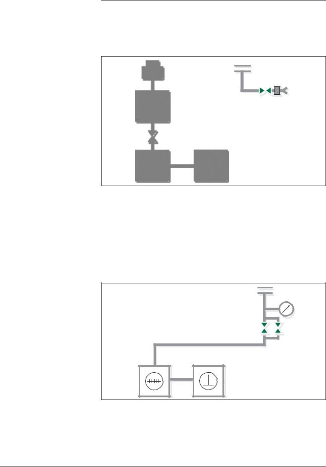
Gross leak test mode (10 mbar to 5x10⁻¹ mbar inlet pressure)
Normal test mode (lower than 5x10⁻¹ mbar inlet pressure)
GB 00208 - Edition 03 - June 08
1 |
|
|
|
3 |
|||
|
2 |
|
|
|
|
||
|
|
|
|
5
18
VR1 VR2
VT1
15
1 |
|
|
|
|
|
|
3 |
|
|
||||
|
|
|
|
|
|
|
|
|
2 |
VT3 |
|
|
|
|
|
|
|
|
||
|
|
|
|
|
|
|
|
|
|
|
|
|
|
|
|
|
|
|
|
|
18 |
|
|
|
|
|
|
VT2 |
|
|
5 |
|||
|
|
|
|
|||
|
|
|
|
|
||
|
|
|
|
|
|
|
VT1
15
3/4
A 200
ASM 142 detector operating principle
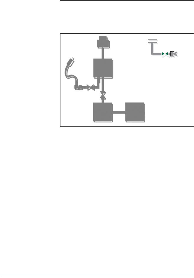
Sniffing test mode
1 |
2 |
3 |
|
|
|
|
|
|
||
|
|
|
|
|
|
|
||||
|
18 |
|
|
|
VA1 |
7 |
|
|||
|
|
|
|
|
||||||
|
|
|
|
|
|
|||||
|
|
|
|
|
||||||
|
|
|
|
|
|
|
|
|
|
|
|
|
|
|
|
|
|
|
|
|
|
|
|
|
|
|
|
|
|
|
|
|
|
|
|
|
|
|
|
|
|
|
|
VT1
8VS
 15
15
GB 00208 - Edition 03 - June 08
4/4
A 201
ASM 142 D detector operating principle
GB 01476 - Edition 03 - June 08
Vacuum circuit
1 |
3 |
|
|
|
2 |
|
|
|
VT3 |
VA1 7 |
|
18 |
|
|
|
|
VC |
|
VT2 |
|
|
|
|
|
5 |
|
|
4 |
VR1 |
VR2 |
8 |
|
|
|
|
VS |
|
|
|
|
|
|
|
|
|
|
VT1 |
|
|
|
|
|
16 |
15 |
Bacosol valve |
10 |
12 |
|
||
|
|
|
||
|
|
|
|
Minisol valves |
Reference correspondence between valve/vacuum block marks |
E 530 |
1 |
Preamplifier |
VA1 |
Inlet vent valve (6 points) |
2 |
Analyzer cell |
VR1 |
Roughing valve (1 point) |
3 |
Detector inlet port |
VR2 |
Roughing valve (2 points) |
4 |
Internal calibrated leak |
VT1 |
Exhaust valve (3 points) |
5 |
Inlet pressure gauge |
VT2 |
Detection valve (4 points) |
7 |
Vent connector |
VT3 |
Detection valve (5 points) |
8 |
Long distance sniffer connector |
VS |
Sniffing valve (9 points) |
10 |
Outlet pump connector |
VC |
Calibration valve (7 points) |
12 |
Purge filter |
|
|
15Roughing pump (AMD1)
16Roughing molecular pump (MDP 5006 HDS)
18 Detection molecular pump (AMP 007I)
1/4

A 201
ASM 142 D detector operating principle
Stand-by mode
1 |
3 |
|
2 |
|
|
|
|
|
|
VA1 |
7 |
18 |
|
|
VT1
16 |
15 |
Roughing mode (Patm to 10 mbar inlet pressure)
|
|
3 |
|
|
5 |
|
VR1 |
VR2 |
|
|
- June 08 |
16 |
15 |
- Edition 03 |
|
|
GB 01476 |
2/4
A 201
ASM 142 D detector operating principle
Gross leak test mode |
|
|
|
|
|
1 |
|
3 |
|
(10 mbar to |
|
2 |
|
|
|
|
|
||
5x10⁻¹ mbar |
18 |
|
|
|
inlet pressure) |
|
|
5 |
|
|
|
|
||
|
|
VT1 |
V |
V |
|
|
R1 |
R2 |
|
|
16 |
|
15 |
|
|
|
|
|
|
|
1 |
2 |
|
3 |
|
|
|
||
|
|
VT2 |
|
|
|
|
|
|
|
Normal test mode |
18 |
|
|
|
|
|
VT3 |
|
|
(lower than |
|
|
5 |
|
|
|
|
||
5x10⁻¹ mbar |
|
VT1 |
|
|
inlet pressure) |
|
|
|
|
|
|
|
|
|
|
16 |
|
|
15 |
GB 01476 - Edition 03 - June 08
3/4
A 201
ASM 142 D detector operating principle
Sniffing test mode
1 |
3 |
|
2 |
|
|
|
|
|
|
VA1 |
7 |
|
18 |
|
VS
8
VT1
|
|
|
16 |
15 |
|
|
|
|
GB 01476 - Edition 03 - June 08
4/4

GB 03710 - Edition 01 - June 08
A 202
ASM 142 Graph D+ detector operating principle
Vacuum circuit
1 |
3 |
|
|
|
2 |
|
|
|
VT3 |
VA1 7 |
|
18 |
|
|
|
|
VC |
|
VT2 |
|
|
|
|
|
5 |
|
|
4 |
VR1 |
VR2 |
8 |
|
|
|
|
VS |
|
|
|
|
|
|
|
|
|
|
VT1 |
|
|
|
|
|
16 |
15 |
Bacosol valve |
10 |
12 |
|
||
|
|
|
||
|
|
|
|
Minisol valves |
Reference correspondence between valve/vacuum block marks |
E 530 |
1 |
Preamplifier |
VA1 |
Inlet vent valve (6 points) |
2 |
Analyzer cell |
VR1 |
Roughing valve (1 point) |
3 |
Detector inlet port |
VR2 |
Roughing valve (2 points) |
4 |
Internal calibrated leak |
VT1 |
Exhaust valve (3 points) |
5 |
Inlet pressure gauge |
VT2 |
Detection valve (4 points) |
7 |
Vent connector |
VT3 |
Detection valve (5 points) |
8 |
Long distance sniffer connector |
VS |
Sniffing valve (9 points) |
10 |
Outlet pump connector |
VC |
Calibration valve (7 points) |
12 |
Purge filter |
|
|
15Roughing primary pump (ACP 15)
16Roughing molecular pump (MDP 5006 HDS)
18 Detection molecular pump (AMP 007I)
1/4
A 202
ASM 142 Graph D+ detector operating principle
Stand-by mode
1 |
3 |
|
2 |
|
|
|
|
|
|
VA1 |
7 |
18 |
|
|
VT1
16 |
15 |
Roughing mode (Inlet pressure: Patm to 10 mbar)
|
|
3 |
|
|
5 |
|
VR1 |
VR2 |
|
|
- June 08 |
16 |
15 |
- Edition 01 |
|
|
GB 03710 |
2/4
A 202
ASM 142 Graph D+ detector operating principle
Gross leak test mode |
|
|
|
|
|
1 |
|
3 |
|
(Inlet pressure: |
|
2 |
|
|
|
|
|
||
10 mbar to |
18 |
|
|
|
5x10⁻¹ mbar) |
|
|
5 |
|
|
|
|
||
|
|
VT1 |
V |
V |
|
|
R1 |
R2 |
|
|
16 |
|
15 |
|
|
|
|
|
|
|
1 |
2 |
|
3 |
|
|
|
||
|
|
VT2 |
|
|
|
|
|
|
|
Normal test mode |
18 |
|
|
|
|
|
VT3 |
|
|
(Inlet pressure: lower |
|
|
5 |
|
|
|
|
||
than 5x10⁻¹ mbar) |
|
VT1 |
|
|
|
|
|
|
|
|
16 |
|
|
15 |
GB 03710 - Edition 01 - June 08
3/4

A 202
ASM 142 Graph D+ detector operating principle
Sniffing test mode
1 |
3 |
|
2 |
|
|
|
|
|
|
VA1 |
7 |
|
18 |
|
VS
8
VT1
|
|
|
16 |
15 |
|
|
|
|
GB 03710 - Edition 01 - June 08
4/4
GB 00007 - Edition 03 - September 04
A 300
Analyzer cell operating principle
Description The analyzer cell works on the principle of mass spectrometry and is set to the mass of helium (m/e = 4).
m/e = atomic mass of the particle/number of electrons lost on ionization
The principle of magnetic deflexion spectrometry is as follows. The neutral molecules of the gas being analyzed pass into an ionization chamber (or source of ions) where they are bombarded by an electron beam generated by a heated tungsten filament. A large number of the molecules are transformed into ions.
He
|
He |
|
|
|
|
||
|
|
|
|
|
|
|
|
|
|
|
He |
6 |
|
|
Leak Signal |
He |
|
Analyzer cell - functional diagram
1/3

A 300
Analyzer cell operating principle
Description (continued) These ionized particles are accelerated by an electrical field.
The entire analyzer cell is subject to a magnetic field which has the property of deflecting the trajectories of the ions along different curves according to the masses of those ions (to be more precised, according to their m/e ratios). Thus the ions beam, which contained ions with different masses, is divided into several beams, each containing
only ions with the same m/e ratio. The helium ions (m/e = 4) are separated from the lighter (H2+ or H1+, smaller beams) or heavier ions (N2+ or O2+, small beams).
Because there is a constant magnetic |
field (permanent magnet), the |
||
accelerator electrical field is adjusted |
so that the helium ions (m/e |
||
= 4) follow a pre-determined trajectory |
(passing |
through diaphragms) |
|
and arrive on the target at the input to |
a direct |
current amplifier. |
|
The current of helium ions is proportional to the partial pressure of helium in the installation and by measuring it we can find the flow rate of the leak that has been detected.
It is essential that the total pressure in the analyzer cell is less than 10-4 mbar, so that the trajectories of the electrons and the ions are not disturbed by residual molecules.
Around 10-3 mbar there is a risk of damaging the heated filament.
In order to separate the helium ions from «noise» caused by «stray ions», an electrode located in front of the target eliminates the secondary ions with low energies. This electrode is called the «braking electrode».
There is an auxiliary electrode at the top of the cell, shaped like a plate, which collects the ions that are heavier than helium. This electrode thus measures the total pressure in the analyzer. This electrode serves as the plate for a triode gauge, hence its name of «triode electrode».
GB 00007 - Edition 03 - September 04
2/3

GB 00007 - Edition 03 - September 04
A 300
Analyzer cell operating principle
Design and manufacture
Great care has been |
taken with the design and |
manufacture of |
|
the cell in order |
to repeatedly obtain the same |
characteristics |
|
and to achieve |
excellent stability: |
|
|
– the metal parts are |
made of stainless steel, |
|
|
– the filament holder |
is made of machined aluminium, |
||
– there is an integral |
amplifier. |
|
|
The cell assembly is composed of:
–a vacuum chamber or deflection chamber,
–an optic holder flange,
–a permanent magnet,
–an amplifier.
• The vacuum chamber: |
|
|
||
The analysis |
cell vacuum chamber is made of light alloy. It is |
|||
hollow with a rectangular opening into which the electrodes, |
||||
(that are installed on the «optics holder» flange) are |
placed. |
|||
• The optics holder flange: |
|
and electrical |
||
The optics holder flange supports all the electrodes |
||||
connections |
in the cell. They include: |
|
||
– the sealed |
power supply socket, mounted on a metal gasket, |
|||
– the amplifier, |
mounted on an elastomer gasket, |
on which the |
||
vthe supporting |
block which screens |
the target and |
||
source of ions is mounted, |
up of 2 parts: |
|
||
– the source |
of ions, which is made |
|
||
•a filament holder,
•an ionization chamber with a stainless steel electron collector and a mass ion emitter.
The filament holder mechanically positions the tungsten filament with respect to the ionization chamber.
The electron collector and the filament have been designed and positioned so that the temperature of the electron collector stabilizes at 400°C under bombardment and radiation from the
filament. The cell is thus rendered immune to contamination from the pieces being tested without the need of any special heating system.
3/3
GB 00008 - Edition 05 - February 02
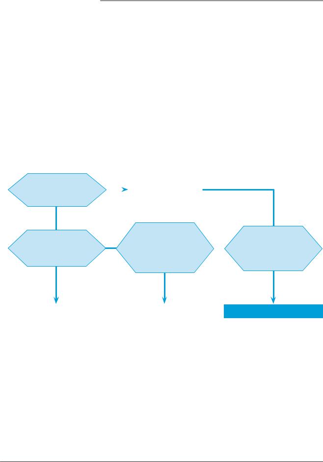
A 400
Testing methods
Overview Leak detection is used to detect micro-openings, porosities, etc. in test parts. The detection of these cracks involves the use of a light tracer gas, which is capable of infiltrating the smallest leak quickly: Helium.
The detector samples and measures the helium flow rate entering the test part via the leak(s).
The testing method is selected according to the test part and the measurement accuracy required:
The part can be |
|
no |
The part is sealed |
||
connected |
to |
|
|
||
|
|
||||
an evacuation |
line |
|
|
|
|
yes |
|
|
|
|
|
|
|
|
|
Its characteristics |
|
Its characteristics |
|
no |
allow it to be |
||
allow it to be |
|
|
pressurized |
with helium |
|
evacuated |
|
|
or a mixture |
containing |
|
|
|
|
|
helium |
|
yes |
|
|
|
|
yes |
|
SPRAY method |
|
SNIFFING method |
laeak rate measurement from 10-10 |
Minimum detectable leak of 10-6 |
||
to 10-1 |
mbar. l/s and possibility of |
mbar.l/s and possibility of locating |
|
locating |
the leak. |
the leak. |
|
Its characteristics allow it to be placed in a vacuum
vessel
yes
BOMBING method
The sensitivity is limited by the internal dead volume of the part as well as on the bombing time and the pressurization value.
Global test without possible location of the leak.
1/4
A 400
Testing methods
Helium concentration and signal displayed
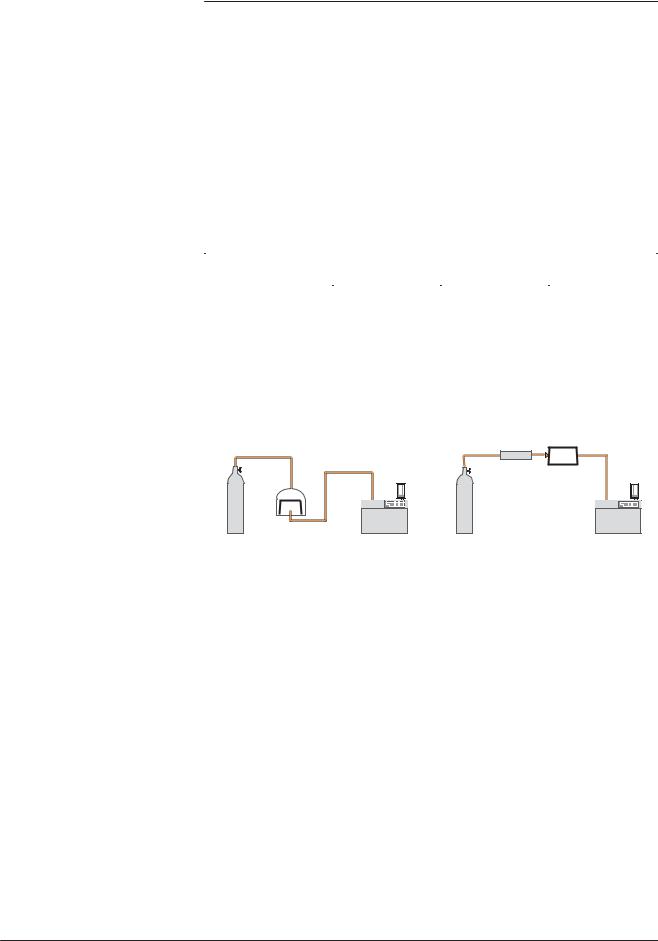
Spray method (inboard testing)
Response time
In accordance to the He concentration rate in the gas used for the leak detection, the signal displayed will change.
Example: signal displayed with a 1x10⁻⁷ mbar.l/s calibrated leak (with 100 % He) connected to the detector inlet.
% He in the gas used |
100 % |
10 % |
1 % |
|
Signal displayed |
1x10⁻⁷ mbar.l/s |
1x10⁻⁸ mbar.l/s |
1x10⁻⁹ mbar.l/s |
|
on the leak detector |
||||
|
|
|
||
|
|
|
|
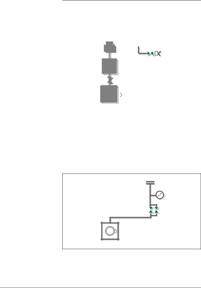
This involves removing air from the test part, connecting it to the analyzer and then spraying helium over the outer surface.
Global test |
Spray test |
|
or |
|
part |
|
spray probe |
He |
part |
|
detector |
The part is placed under a cover, into which helium is injected.
The leak cannot be located.
He
detector
Potential leaking areas are sprayed with helium.
The leak can be located.
The detector measures the flow of helium penetrating the part.
When spraying starts, the leak signal is not displayed instantaneously on the analyzer:
there is a response time which depends on the volume V being tested
and |
the helium pumping speed S of the system at the opening of the |
|
part, |
according to the following relation: |
|
T = |
V/S |
(T in seconds, V in litres, S in l/s) |
T is the time required for the signal to reach 63 % of the final value.
GB 00008 - Edition 05 - February 02
2/4
A 400
Testing methods
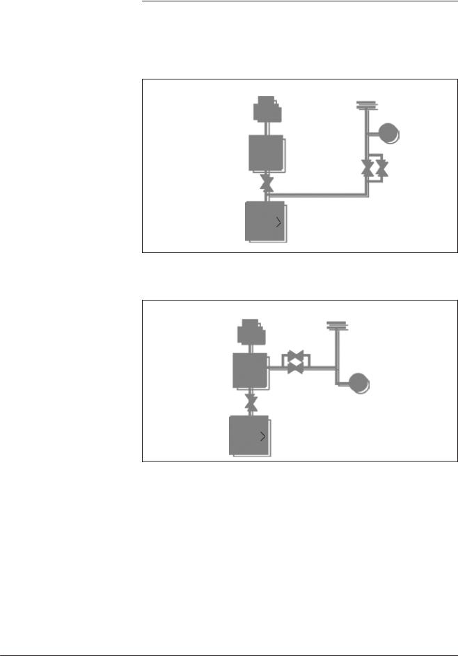
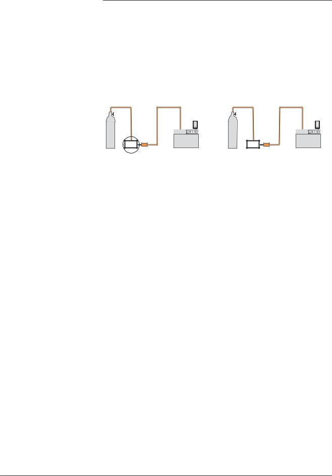
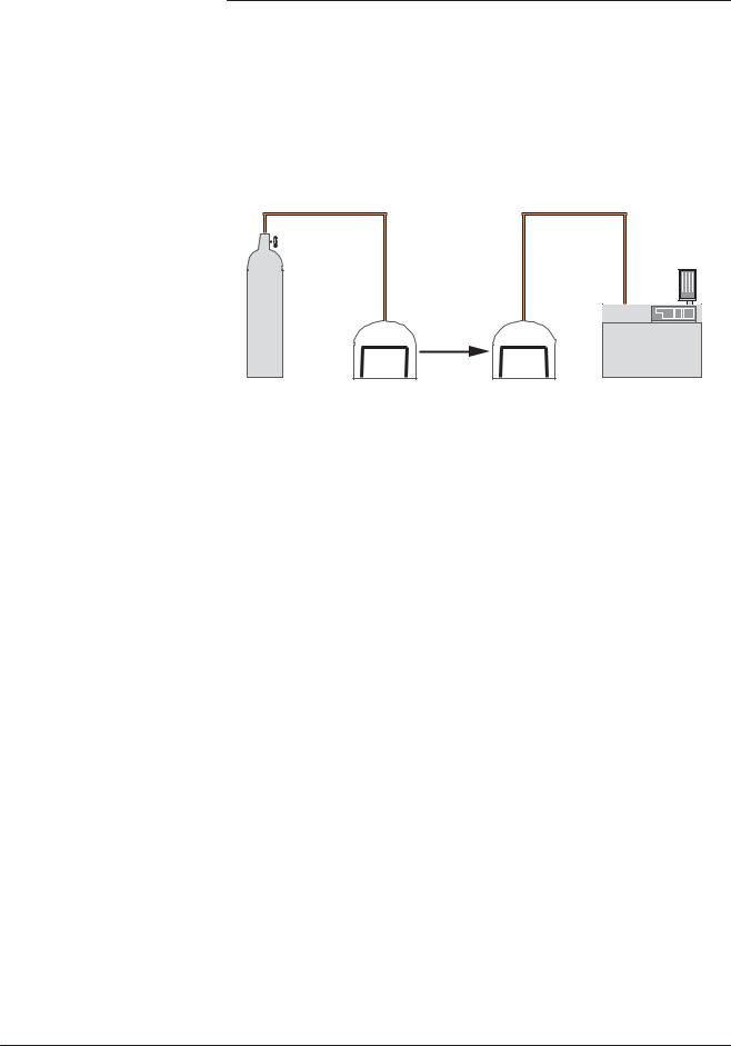
Sniffer method (outboard testing)
The test part is pressurized with helium. The detector, via an LDS (Long Distance Sniffer) probe, samples the helium escaping from the part.
Global test |
Local sniffing test |
or
He |
|
part |
detector |
|
LDS |
The part is placed under a cover containing a sniffer probe.
The leak cannot be located.
The helium from the leak accumulates over time inside the cover. The detector measures the concentration of helium.
He |
|
part |
detector |
|
LDS |
The sniffer probe is moved over areas likely to contain leaks.
The leak can be located.
The signal supplied by the analyzer is not a direct measurement of the leak.
The sniffer probe only samples part of the helium escaping from the part. The sample depends on the distance separating the leak from the tip of the probe.
GB 00008 - Edition 05 - February 02
3/4
A 400
Testing methods
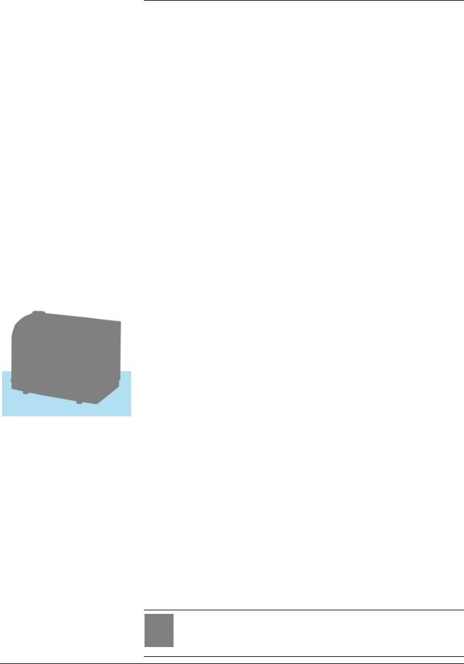
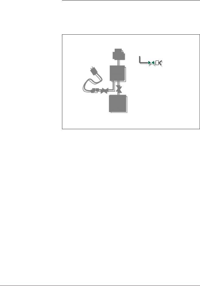
Bombing method This method is used for sealed objects that cannot be connected directly to the detector (semiconductors, waterproof watches, etc.).
He
He |
|
|
part |
part |
detector |
Chamber 1 |
Chamber |
2 |
The part is placed in a chamber containing pressurized helium.
The helium penetrates the part if it has a leak.
The part is then removed from the chamber and placed in another vacuum chamber which is connected to the detector. The helium escapes from the part through the leak and produces a signal.
This signal is not a direct measurement of the leak as the helium pressure inside the part is difficult to determine. Several parts play an important part such as: the pressurization time, the helium bombing pressure, the internal volume, the aeration time, the size of the leak.
GB 00008 - Edition 05 - February 02
4/4

GB 02760 - Edition 02 - June 08
A 401
About Helium and hydrogen
Helium |
Helium is the second most common element in the universe, |
|
representing about 23 % of the total matter. 76 % is Hydrogen. All |
|
other elements represent an insignificantly small fraction of the total. |
|
Helium was discovered by spectroscopy in a solar eclipse on August |
|
18, 1868. The discovery in the sun’s chronosphere gave the new |
|
element its name: “helios” in Greek means “sun”. While Helium is |
|
very common in the universe most of it is in the stars: on earth it |
|
is actually not abundant. Since it is so light all the Helium present |
|
during the formation of earth escaped to space. Helium is created, |
|
deep in the earth from the radioactive decay of Uranium and Thorium |
|
which also generates the earth its internal heat. On earth Helium was |
|
discovered in 1881 by spectroscopy of Mount Vesuvio in Italy – the |
|
volcanic gases emanated by the mountain showed the same lines in |
|
the spectrum as already known from the sun. |
|
Helium concentration in the atmosphere is 5 times bigger than the one |
|
of Krypton and 60 times higher than Xenon. The heavier noble gases |
|
are isolated from air by liquefaction and rectification process. Helium |
|
as a contrary is “extracted” from natural gas and oil wells. Helium |
|
comes up with the natural gas and is separated and stored. The |
|
annual world wide production is ca. 3x10⁷ m3 or |
|
4,500 tons. |
|
Helium is constantly seeping up from the ground all around us, but it |
|
is so light that almost all of it escapes into space fairly rapidly. On the |
|
other hand there is a constant flow of Helium from space and the sun |
|
to earth. This gives a dynamic equilibrium and is the reason for the |
|
world wide constant concentration of ca. 5 ppm Helium in air. |
|
Helium is a very light colorless element and it is one of the six noble |
|
gases; it is the most difficult gas to liquefy. |
|
Helium is a noble gas, which means it doesn’t react with anything for |
|
all practical intents and purposes. It’s used as an inert shield gas to |
|
protect things from oxidation – and of course as leak detection tracer |
|
gas. |
|
Helium is a 100 % green gas and has absolutely no environmental |
|
impact on the atmosphere. |
1/2
 Loading...