


 Loading...
Part No. 060211-10, Rev.E
June 2007
OmniSwitch 9000 Series
Hardware Users Guide
www.alcatel-lucent.com

This user guide documents OmniSwitch 9000 Series hardware, including chassis and associated components.
The specifications described in this guide are subject to change without notice.
Copyright © 2007 by Alcatel-Lucent. All rights reserved. This document may not be reproduced in whole or in part without the express written permission of Alcatel-Lucent.
Alcatel-Lucent® and the Alcatel-Lucent logo are registered trademarks of Alcatel-Lucent. Xylan®, OmniSwitch®, OmniStack®, and Alcatel-Lucent OmniVista® are registered trademarks of Alcatel-Lucent.
OmniAccess™, Omni Switch/Router™, PolicyView™, RouterView™, SwitchManager™, VoiceView™, WebView™, X-Cell™, X-Vision™, and the Xylan logo are trademarks of Alcatel-Lucent.
This OmniSwitch product contains components which may be covered by one or more of the following U.S. Patents:
•U.S. Patent No. 6,339,830
•U.S. Patent No. 6,070,243
•U.S. Patent No. 6,061,368
•U.S. Patent No. 5,394,402
•U.S. Patent No. 6,047,024
•U.S. Patent No. 6,314,106
•U.S. Patent No. 6,542,507
•U.S. Patent No. 6,874,090
26801 West Agoura Road
Calabasas, CA 91301
(818) 880-3500 FAX (818) 880-3505 support@ind.alcatel.com
US Customer Support—(800) 995-2696 International Customer Support—(818) 878-4507 Internet—service.esd.alcatel-lucent.com
ii |
June 2007 |

Contents
|
About This Guide .......................................................................................................... |
ix |
|
Supported Platforms .......................................................................................................... |
ix |
|
Who Should Read this Manual? ........................................................................................ |
ix |
|
When Should I Read this Manual? ..................................................................................... |
x |
|
What is in this Manual? ...................................................................................................... |
x |
|
What is Not in this Manual? ............................................................................................... |
x |
|
How is the Information Organized? .................................................................................. |
xi |
|
Documentation Roadmap .................................................................................................. |
xi |
|
Related Documentation ................................................................................................... |
xiii |
|
User Manual CD ............................................................................................................. |
xiv |
|
Technical Support ........................................................................................................... |
xiv |
Chapter 1 |
OmniSwitch 9000 Series ........................................................................................ |
1-1 |
|
Application Example ....................................................................................................... |
1-2 |
|
Availability Features ....................................................................................................... |
1-3 |
|
Hardware Redundancy ............................................................................................. |
1-3 |
|
Smart Continuous Switching .................................................................................... |
1-4 |
|
Software Rollback .................................................................................................... |
1-4 |
|
Hot Swapping ........................................................................................................... |
1-5 |
|
Hardware Monitoring ............................................................................................... |
1-5 |
|
Power Checking Sequence ....................................................................................... |
1-6 |
Chapter 2 |
Chassis and Power Supplies .................................................................................... |
2-1 |
|
OmniSwitch 9800 ............................................................................................................ |
2-2 |
|
OmniSwitch 9700 ............................................................................................................ |
2-5 |
|
OmniSwitch 9600 ............................................................................................................ |
2-8 |
|
Chassis Slot Numbering ................................................................................................ |
2-11 |
|
Viewing Chassis Slot Information ......................................................................... |
2-12 |
|
Mounting the Switch ..................................................................................................... |
2-12 |
|
Power Supplies .............................................................................................................. |
2-16 |
|
600 Watt DC-to-DC Power Supply ........................................................................ |
2-18 |
|
DC Power Supply Connection ............................................................................... |
2-19 |
|
Connecting the DC Cable Harness to the Chassis Power Supply ................... |
2-19 |
|
Connecting the DC Cable Harness to the DC Power Source .......................... |
2-19 |
|
Chassis Power Supply Module Support ........................................................................ |
2-20 |
OmniSwitch 9000 Series Hardware Users Guide June 2007 |
iii |

|
|
Contents |
|
|
|
|
|
|
|
Monitoring Chassis Power ............................................................................................ |
2-21 |
|
Checking Chassis Power Before Adding a Module ............................................... |
2-21 |
|
Example 1: Adequate Power to Add a Module ............................................... |
2-22 |
|
Example 2: Inadequate Power to Add a Module ............................................. |
2-23 |
|
Checking Chassis Power Before Shutting Off or Removing a Power Supply ....... |
2-25 |
|
Example 1: Adequate Power to Remove a Power Supply .............................. |
2-25 |
|
Example 2: Inadequate Power to Remove a Power Supply ............................ |
2-26 |
|
Adding a Power Supply .......................................................................................... |
2-26 |
|
Hot Swapping a Power Supply ............................................................................... |
2-26 |
|
Permanently Removing a Power Supply ................................................................ |
2-26 |
|
Power Supply Redundancy ........................................................................................... |
2-27 |
|
Redundancy Defined .............................................................................................. |
2-27 |
|
Installing a Power Supply ............................................................................................. |
2-28 |
|
Removing a Power Supply ..................................................................................... |
2-30 |
|
Power Cords .................................................................................................................. |
2-31 |
|
Redundant AC Circuit Recommendation ...................................................................... |
2-32 |
|
Grounding the Chassis ........................................................................................... |
2-33 |
|
Temperature Management ............................................................................................ |
2-33 |
|
Temperature Errors .......................................................................................... |
2-34 |
|
Chassis Fan Tray ........................................................................................................... |
2-35 |
|
Monitoring Fan Tray Status ............................................................................. |
2-37 |
|
Fan Redundancy .............................................................................................. |
2-37 |
|
Hot Swapping the Fan Tray ............................................................................. |
2-37 |
|
Removing the Fan Tray ................................................................................... |
2-38 |
|
Installing the New Fan Tray ............................................................................ |
2-39 |
|
Chassis Airflow ............................................................................................................. |
2-40 |
|
Power Supply Fans ................................................................................................. |
2-43 |
|
Blank Cover Panels and Chassis Airflow .............................................................. |
2-44 |
Chapter 3 |
Installing and Managing Power over Ethernet (PoE) ...................................... |
3-1 |
|
In This Chapter ................................................................................................................ |
3-2 |
|
Power over Ethernet Specifications ................................................................................ |
3-3 |
|
Power over Ethernet Overview ....................................................................................... |
3-4 |
|
Power over Ethernet Components ................................................................................... |
3-6 |
|
OS-IP-SHELF PoE Power Shelf .............................................................................. |
3-6 |
|
510W/360W Power Supply ...................................................................................... |
3-8 |
|
Power Shelf and PoE Port Guidelines ............................................................................. |
3-9 |
|
Non-Redundant Power Supply Configurations ........................................................ |
3-9 |
|
Redundant Power Supply Configurations .............................................................. |
3-10 |
|
Setting Up Power over Ethernet Hardware ................................................................... |
3-11 |
|
Basic Guidelines for Setting Up PoE Hardware .................................................... |
3-11 |
|
Positioning the Power Shelf ............................................................................ |
3-11 |
|
Rack-Mounting the Power Shelf ..................................................................... |
3-12 |
iv |
OmniSwitch 9000 Series Hardware Users Guide June 2007 |

Contents
|
|
|
|
|
|
|
.................................................................................Installing the Power Supplies |
3-15 |
|
Preparation ....................................................................................................... |
3-15 |
|
Installation Steps ............................................................................................. |
3-15 |
|
Removing the Power Supplies ............................................................................... |
3-17 |
|
Connecting the Power Shelf to the Chassis ............................................................ |
3-19 |
|
Connecting the 360W/510W PoE Power Supply to the Chassis ........................... |
3-20 |
|
Power Shelf Slot Numbering ........................................................................................ |
3-21 |
|
Viewing Power Shelf Status .......................................................................................... |
3-22 |
|
Configuring Power over Ethernet Parameters ............................................................... |
3-23 |
|
Power over Ethernet Defaults ................................................................................ |
3-23 |
|
Understanding and Modifying the Default Settings ............................................... |
3-23 |
|
Setting the PoE Operational Status .................................................................. |
3-23 |
|
Configuring the Total Power Allocated to a Port ............................................ |
3-24 |
|
Configuring the Total Power Allocated to a Slot ............................................ |
3-24 |
|
Setting Port Priority Levels ............................................................................. |
3-25 |
|
Setting PoE Redundancy Status ...................................................................... |
3-26 |
|
Setting the Capacitor Detection Method ......................................................... |
3-26 |
|
Understanding Priority Disconnect ............................................................................... |
3-27 |
|
Setting Priority Disconnect Status .......................................................................... |
3-27 |
|
Disabling Priority Disconnect ......................................................................... |
3-27 |
|
Enabling Priority Disconnect .......................................................................... |
3-27 |
|
Priority Disconnect is Enabled; Same Priority Level on All PD Ports ........... |
3-28 |
|
Priority Disconnect is Enabled; Incoming PD Port has Highest |
|
|
Priority Level ................................................................................................... |
3-29 |
|
Priority Disconnect is Enabled; Incoming PD Port has Lowest |
|
|
Priority Level ................................................................................................... |
3-30 |
|
Priority Disconnect is Disabled ....................................................................... |
3-31 |
|
Monitoring Power over Ethernet via the CLI ............................................................... |
3-32 |
|
Power over Ethernet Tutorial ........................................................................................ |
3-34 |
Chapter 4 |
Chassis Management Module (CMM) ................................................................... |
4-1 |
|
CMM Slot Locations ....................................................................................................... |
4-2 |
|
OS9700-CMM Versus OS9800-CMM .............................................................. |
4-2 |
|
CMM Front Panel ........................................................................................................... |
4-3 |
|
Ethernet Management Port (EMP) ........................................................................... |
4-5 |
|
Access to the EMP ............................................................................................. |
4-6 |
|
EMP Cable Requirements ................................................................................. |
4-6 |
|
Console Port ............................................................................................................. |
4-6 |
|
Serial Connection to the Console Port ............................................................... |
4-6 |
|
Configuring X-ON/X-OFF Protocol ........................................................................ |
4-8 |
|
CMM Redundancy .......................................................................................................... |
4-9 |
|
CMM Failover Sequence ......................................................................................... |
4-9 |
|
Synchronizing the Primary and Secondary CMMs ................................................ |
4-10 |
|
CMM Switching Fabric .......................................................................................... |
4-10 |
|
Hot Swapping CMM Modules ...................................................................................... |
4-11 |
|
Module Presence Signalling ............................................................................ |
4-11 |
|
Hot Swap Requirements ......................................................................................... |
4-11 |
OmniSwitch 9000 Series Hardware Users Guide June 2007 |
v |

|
|
Contents |
|
|
|
|
|
|
|
Managing CMM Modules ............................................................................................. |
4-13 |
|
Reloading a CMM Module .................................................................................... |
4-13 |
|
Switching the Primary and Secondary Roles ......................................................... |
4-13 |
|
Monitoring CMM Modules ........................................................................................... |
4-14 |
|
Front Panel LEDs ................................................................................................... |
4-14 |
|
Accessing General CMM Information ................................................................... |
4-14 |
|
CMM Hardware Information .......................................................................... |
4-14 |
|
Operating Status of CMM-Related Components ............................................ |
4-15 |
|
CLI Commands Supported on Both the Primary and Secondary CMMs ....... |
4-15 |
|
Chassis-Based MAC Address ....................................................................................... |
4-17 |
|
Pinouts ........................................................................................................................... |
4-17 |
Chapter 5 |
Network Interface (NI) Modules ............................................................................ |
5-1 |
|
In This Chapter ................................................................................................................ |
5-1 |
|
GNI Modules ................................................................................................................... |
5-3 |
|
OS9-GNI-C24 Front Panel ....................................................................................... |
5-4 |
|
OS9-GNI-P24 Front Panel ....................................................................................... |
5-6 |
|
OS9-GNI-C20L Front Panel .................................................................................... |
5-8 |
|
OS9-GNI-C48T Front Panel .................................................................................. |
5-10 |
|
RJ-45 to RJ-45 Patch Panel ............................................................................. |
5-12 |
|
MRJ-21to RJ-45 Cable .................................................................................... |
5-13 |
|
OS9-GNI-U24 Front Panel ..................................................................................... |
5-14 |
|
|
5-15 |
|
XNI Modules ................................................................................................................. |
5-16 |
|
OS9-XNI-U2 Front Panel ....................................................................................... |
5-17 |
|
OS9-XNI-U6 Front Pane ........................................................................................ |
5-19 |
|
Smart Continuous Switching ......................................................................................... |
5-21 |
|
Module Priorities During Boot Sequence ........................................................ |
5-21 |
|
Managing NI Modules .................................................................................................. |
5-21 |
|
Turning Power On or Off for a Specific NI Module ....................................... |
5-21 |
|
Individual NI Reload ....................................................................................... |
5-21 |
|
Monitoring NI Modules ................................................................................................ |
5-22 |
|
Front Panel LEDs ............................................................................................ |
5-22 |
|
Accessing General NI Information .................................................................. |
5-22 |
|
Hot Swapping NI Modules ............................................................................................ |
5-23 |
|
Removing and Adding Modules ................................................................................... |
5-24 |
|
Using the Grounding Wrist Strap and Chassis Grounding Lug ............................. |
5-24 |
|
Module Types and Slot Positions ........................................................................... |
5-25 |
|
Removing a Module ............................................................................................... |
5-25 |
|
Adding a Module .................................................................................................... |
5-27 |
|
Pinouts ........................................................................................................................... |
5-29 |
|
10/100 Mbps Ethernet Port – RJ-45 Pinout .......................................................... |
5-29 |
|
1 Gigabit Ethernet Port – RJ-45 Pinout ................................................................. |
5-29 |
|
Handling Fiber and Fiber Optic Connectors ................................................................. |
5-30 |
vi |
OmniSwitch 9000 Series Hardware Users Guide June 2007 |

Contents
|
|
|
|
|
|
Appendix A |
..............................................Regulatory Compliance and Safety Information |
A-1 |
|
Declaration of Conformity: CE Mark ............................................................................ |
A-1 |
|
Waste Electrical and Electronic Equipment (WEEE) Statement ............................ |
A-1 |
|
China RoHS: Hazardous Substance Table ..................................................................... |
A-2 |
|
Standards Compliance .................................................................................................... |
A-4 |
|
FCC Class A, Part 15 .............................................................................................. |
A-4 |
|
Canada Class A Statement ...................................................................................... |
A-4 |
|
JATE ........................................................................................................................ |
A-4 |
|
CISPR22 Class A warning ...................................................................................... |
A-5 |
|
VCCI ....................................................................................................................... |
A-5 |
|
Class A Warning for Taiwan and Other Chinese Markets ...................................... |
A-5 |
|
Translated Safety Warnings ........................................................................................... |
A-6 |
|
Chassis Lifting Warning ................................................................................... |
A-6 |
|
Blank Panels Warning ...................................................................................... |
A-6 |
|
Electrical Storm Warning ................................................................................. |
A-6 |
|
Installation Warning ......................................................................................... |
A-7 |
|
Invisible Laser Radiation Warning ................................................................... |
A-7 |
|
Lithium Battery Warning ................................................................................. |
A-8 |
|
Operating Voltage Warning ............................................................................. |
A-8 |
|
Power Disconnection Warning ......................................................................... |
A-9 |
|
Proper Earthing Requirement Warning ............................................................ |
A-9 |
|
Read Important Safety Information Warning ................................................. |
A-10 |
|
Restricted Access Location Warning ............................................................. |
A-10 |
|
Wrist Strap Warning ....................................................................................... |
A-11 |
|
Instrucciones de seguridad en español ......................................................................... |
A-12 |
|
Advertencia sobre el levantamiento del chasis ............................................... |
A-12 |
|
Advertencia de las tapaderas en blanco .......................................................... |
A-12 |
|
Advertencia en caso de tormenta eléctrica ..................................................... |
A-12 |
|
Advertencia de instalación ............................................................................. |
A-12 |
|
Advertencia de radiación láser invisible ......................................................... |
A-12 |
|
Advertencia de la batería de litio .................................................................... |
A-12 |
|
Advertencia sobre la tensión de operación ..................................................... |
A-12 |
|
Advertencia sobre la desconexión de la fuente .............................................. |
A-12 |
|
Advertencia sobre una apropiada conexión a tierra ....................................... |
A-13 |
|
Leer “información importante de seguridad” ................................................. |
A-13 |
|
Advertencia de acceso restringido .................................................................. |
A-13 |
|
Advertencia de pulsera antiestática ................................................................ |
A-13 |
|
Clase de seguridad .......................................................................................... |
A-13 |
|
Advertencia de fuentes de poder .................................................................... |
A-13 |
|
Index ...................................................................................................................... |
Index-1 |
OmniSwitch 9000 Series Hardware Users Guide June 2007 |
vii |
Contents
|
|
|
|
|
|
viii |
OmniSwitch 9000 Series Hardware Users Guide June 2007 |

About This Guide
This OmniSwitch 9000 Series Hardware Users Guide describes your switch hardware components and basic switch hardware procedures.
Supported Platforms
This information in this guide applies to the following products:
•OmniSwitch 9600
•OmniSwitch 9700
•OmniSwitch 9800
The OmniSwitch 9800 includes 18 slots for high performance 10/100/1000 Ethernet, Gigabit Ethernet, and 10 Gigabit Network Interface (NI) modules. The OmniSwitch 9700 includes 10 slots for high performance 10/100/1000 Ethernet, Gigabit Ethernet, and 10 Gigabit Network Interface (NI) modules. The OmniSwitch 9600 includes 5 slots for high performance 10/100/1000 Ethernet, Gigabit Ethernet, and 10 Gigabit Network Interface (NI) modules.
Unsupported Platforms
The information in this guide does not apply to the following products:
•OmniSwitch (original version with no numeric model name)
•OmniSwitch 6600 Family
•OmniSwitch 6800 Series
•OmniSwitch 7700/7800
•OmniSwitch 8800
•Omni Switch/Router
•OmniStack
•OmniAccess
Who Should Read this Manual?
The audience for this users guide is network administrators and IT support personnel who need to configure, maintain, and monitor switches and routers in a live network. However, anyone wishing to gain knowledge on the OmniSwitch 9000 Series hardware will benefit from the material in this guide.
OmniSwitch 9000 Series Hardware Users Guide June 2007 |
page ix |

When Should I Read this Manual? |
About This Guide |
|
|
|
|
When Should I Read this Manual?
Read this guide as soon as you are ready to familiarize yourself with your switch hardware components. You should have already stepped through the first login procedures and read the brief hardware overviews in the OmniSwitch 9000 Series Getting Started Guide.
You should already be familiar with the very basics of the switch hardware, such as module LEDs and module installation procedures. This manual will help you understand your switch hardware components (chassis, cooling fans, power supplies, Network Interface modules, Chassis Management Modules) in greater depth.
What is in this Manual?
This users guide includes the following hardware-related information:
•Descriptions of “Availability” features.
•Technical specifications for chassis, power supplies, Network Interface (NI) modules, and Chassis Management Modules (CMMs).
•Power supply requirements.
•The dynamics of chassis airflow, including detailed illustrations of proper and improper airflow configurations.
•Hot swapping power supplies, fan trays, Network Interface (NI) modules, and Chassis Management Modules (CMMs).
•Installation and removal procedures for power supplies, fan trays, Network Interface (NI) modules, and Chassis Management Modules (CMMs).
•Detailed illustrations and LED descriptions for power supplies, Network Interface (NI) modules, and Chassis Management Modules (CMMs).
•CMM redundancy.
•Hardware-related Command Line Interface (CLI) commands.
What is Not in this Manual?
The descriptive and procedural information in this manual focuses on switch hardware. It includes information on some CLI commands that pertain directly to hardware configuration, but it is not intended as a software users guide. There are several OmniSwitch 9000 Series users guides that focus on switch software configuration. Consult those guides for detailed information and examples for configuring your switch software to operate in a live network environment. See “Documentation Roadmap” on page -xi and “Related Documentation” on page -xiii for further information on software configuration guides available for your switch.
page x |
OmniSwitch 9000 Series Hardware Users Guide June 2007 |
About This Guide |
How is the Information Organized? |
|
|
|
|
How is the Information Organized?
Each chapter in this guide focuses on a specific hardware component, such as the Chassis Management Module (CMM), or a set of hardware components. All descriptive, technical specification, and procedural information for a hardware component can be found in the chapter dedicated to that component.
Documentation Roadmap
The OmniSwitch 9000 Series user documentation suite was designed to supply you with information at several critical junctures of the configuration process.The following section outlines a roadmap of the manuals that will help you at each stage of the configuration process. Under each stage, we point you to the manual or manuals that will be most helpful to you.
Stage 1: Using the Switch for the First Time
Pertinent Documentation: OmniSwitch 9000 Series Getting Started Guide
Release Notes
A hard-copy OmniSwitch 9000 Series Getting Started Guide is included with your switch; this guide provides all the information you need to get your switch up and running the first time. It provides information on unpacking the switch, rack mounting the switch, installing NI modules, unlocking access control, setting the switch’s IP address, and setting up a password. It also includes succinct overview information on fundamental aspects of the switch, such as hardware LEDs, the software directory structure, CLI conventions, and web-based management.
At this time you should also familiarize yourself with the Release Notes that accompanied your switch. This document includes important information on feature limitations that are not included in other user guides.
Stage 2: Gaining Familiarity with Basic Switch Functions
Pertinent Documentation: OmniSwitch 9000 Series Hardware Users Guide OmniSwitch 6800/6850/9000 Switch Management Guide
Once you have your switch up and running, you will want to begin investigating basic aspects of its hardware and software. Information about switch hardware is provided in the OmniSwitch 9000 Series Hardware Guide. This guide provide specifications, illustrations, and descriptions of all hardware components, such as chassis, power supplies, Chassis Management Modules (CMMs), Network Interface (NI) modules, and cooling fans. It also includes steps for common procedures, such as removing and installing switch components.
The OmniSwitch 6800/6850/9000 Switch Management Guide is the primary users guide for the basic software features on a single switch. This guide contains information on the switch directory structure, basic file and directory utilities, switch access security, SNMP, and web-based management. It is recommended that you read this guide before connecting your switch to the network.
OmniSwitch 9000 Series Hardware Users Guide June 2007 |
page xi |

Documentation Roadmap |
About This Guide |
|
|
|
|
Stage 3: Integrating the Switch Into a Network
Pertinent Documentation: OmniSwitch 6800/6850/9000 Network Configuration Guide OmniSwitch 6800/6850/9000 Advanced Routing Configuration Guide
When you are ready to connect your switch to the network, you will need to learn how the OmniSwitch implements fundamental software features, such as 802.1Q, VLANs, Spanning Tree, and network routing protocols. The OmniSwitch 6800/6850/9000 Network Configuration Guide contains overview information, procedures, and examples on how standard networking technologies are configured in the OmniSwitch 9000 Series.
The OmniSwitch 6800/6850/9000 Advanced Routing Configuration Guide includes configuration information for networks using advanced routing technologies (OSPF and BGP) and multicast routing protocols (DVMRP and PIM-SM).
Anytime
The OmniSwitch CLI Reference Guide contains comprehensive information on all CLI commands supported by the switch. This guide includes syntax, default, usage, example, related CLI command, and CLI-to-MIB variable mapping information for all CLI commands supported by the switch. This guide can be consulted anytime during the configuration process to find detailed and specific information on each CLI command.
page xii |
OmniSwitch 9000 Series Hardware Users Guide June 2007 |

About This Guide |
Related Documentation |
|
|
|
|
Related Documentation
The following are the titles and descriptions of all the OmniSwitch 9000 Series user manuals:
•OmniSwitch 9000 Series Getting Started Guide
Describes the hardware and software procedures for getting an OmniSwitch 9000 Series up and running. Also provides information on fundamental aspects of OmniSwitch software architecture.
•OmniSwitch 9000 Series Hardware Users Guide
Complete technical specifications and procedures for all OmniSwitch 9000 Series chassis, power supplies, fans, and Network Interface (NI) modules.
•OmniSwitch CLI Reference Guide
Complete reference to all CLI commands supported on the OmniSwitch 6800, 6850, and 9000. Includes syntax definitions, default values, examples, usage guidelines and CLI-to-MIB variable mappings.
•OmniSwitch 6800/6850/9000 Switch Management Guide
Includes procedures for readying an individual switch for integration into a network. Topics include the software directory architecture, image rollback protections, authenticated switch access, managing switch files, system configuration, using SNMP, and using web management software (WebView).
•OmniSwitch 6800/6850/9000 Network Configuration Guide
Includes network configuration procedures and descriptive information on all the major software features and protocols included in the base software package. Chapters cover Layer 2 information (Ethernet and VLAN configuration), Layer 3 information (routing protocols, such as RIP and IPX), security options (authenticated VLANs), Quality of Service (QoS), link aggregation, and server load balancing.
•OmniSwitch 6800/6850/9000 Advanced Routing Configuration Guide
Includes network configuration procedures and descriptive information on all the software features and protocols included in the advanced routing software package. Chapters cover multicast routing (DVMRP and PIM-SM), Open Shortest Path First (OSPF), and Border Gateway Protocol (BGP).
•OmniSwitch Transceivers Guide
Includes SFP and XFP transceiver specifications and product compatibility information.
•Technical Tips, Field Notices
Includes information published by Alcatel-Lucent’s Customer Support group.
•Release Notes
Includes critical Open Problem Reports, feature exceptions, and other important information on the features supported in the current release and any limitations to their support.
OmniSwitch 9000 Series Hardware Users Guide June 2007 |
page xiii |

User Manual CD |
About This Guide |
|
|
|
|
User Manual CD
All user guides for the OmniSwitch 9000 Series are included on the User Manual CD that accompanied your switch. This CD also includes user guides for other Alcatel-Lucent data enterprise products. In addition, it contains a stand-alone version of the on-line help system that is embedded in the OmniVista network management application.
Besides the OmniVista documentation, all documentation on the User Manual CD is in PDF format and requires the Adobe Acrobat Reader program for viewing. Acrobat Reader freeware is available at www.adobe.com.
Note. In order to take advantage of the documentation CD’s global search feature, it is recommended that you select the option for searching PDF files before downloading Acrobat Reader freeware.
To verify that you are using Acrobat Reader with the global search option, look for the following button in the toolbar:
Note. When printing pages from the documentation PDFs, de-select Fit to Page if it is selected in your print dialog. Otherwise pages may print with slightly smaller margins.
Technical Support
An Alcatel-Lucent service agreement brings your company the assurance of 7x24 no-excuses technical support. You’ll also receive regular software updates to maintain and maximize your Alcatel-Lucent product’s features and functionality and on-site hardware replacement through our global network of highly qualified service delivery partners. Additionally, with 24-hour-a-day access to Alcatel-Lucent’s Service and Support web page, you’ll be able to view and update any case (open or closed) that you have reported to Alcatel-Lucent’s technical support, open a new case or access helpful release notes, technical bulletins, and manuals. For more information on Alcatel-Lucent’s Service Programs, see our web page at service.esd.alcatel-lucent.com, call us at 1-800-995-2696, or email us at support@ind.alcatel.com.
page xiv |
OmniSwitch 9000 Series Hardware Users Guide June 2007 |
1 OmniSwitch 9000 Series
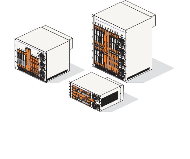
OmniSwitch 9000 switches offer high performance 10/100/1000 Ethernet, Gigabit Ethernet, and 10 Gigabit Ethernet capabilities, as well as embedded server load balancing for enterprise requirements. In this release, these switches come in three chassis configurations—the 18-slot OmniSwitch 9800 (OS9800), the 10-slot OmniSwitch 9700 (OS9700), and the 5-slot OmniSwitch 9600 (OS9600).
Full duplex is supported on Gigabit Ethernet ports and 10-gigabit Ethernet ports.
Refer to the sections below for additional details on OS9000 switches.
OmniSwitch 9000 Series
The 18-slot OS9800 offers up to 768 Gigabit Ethernet ports and up to ninety-six 10-Gigabit Ethernet ports.The 10-slot OS9700 offers up to 384 Gigabit Ethernet ports and up to fourty-eight10-gigabit Ethernet ports while the 5-slot OS9600 offers up to 192 Gigabit Ethernet ports and up to twenty-four 10-gigabit Ethernet ports.
OmniSwitch |
9800 |
|
|
|
|
|
||
|
|
|
|
|
|
|
|
|
1 |
|
|
|
|
|
|
|
|
9 |
2 |
NI |
|
|
|
|
|
|
|
10 |
|
3 |
|
|
|
|
|
|
|
|
11 |
4 |
|
|
|
|
|
|
|
|
12 |
CMM |
|
|
|
|
|
|
|
A |
|
|
|
|
|
|
|
|
CMM-OS9800 |
B |
14 |
|
|
|
|
|
|
OS9800 |
7 |
|
||
|
|
|
|
|
5 |
|
|
|
|
|
|
|
|
13 |
6 |
NI |
|
|
|
|
|
|
CMM- |
|
8 |
|
|
|
|
|
|
|
|
15 |
|
|
|
|
|
|
|
|
16 |
PWR |
|
|
|
|
|
|
|
|
PS1 |
|
|
|
|
|
|
|
|
PS2 |
|
|
|
|
|
|
|
|
PS3 |
|
|
|
|
|
|
|
|
PS4 |
OmniSwitch |
9700 |
|
A
1
2 |
NI |
3
4
CMM
B
PWR
PS1
PS2
PS3
5
6 |
NI |
7
8
OmniSwitchOS9
-XNI-U2
9600
OS9- |
GNI-C24 |
OS9600/OS9700- |
CMM |
OS9- |
XNI-U2 |
OS9- |
GNI-C24 |
OmniSwitch OS9600, OS9700, OS9800
OmniSwitch 9000 Series Hardware Users Guide June 2007 |
page 1-1 |
Application Example |
OmniSwitch 9000 Series |
|
|
|
|
Application Example
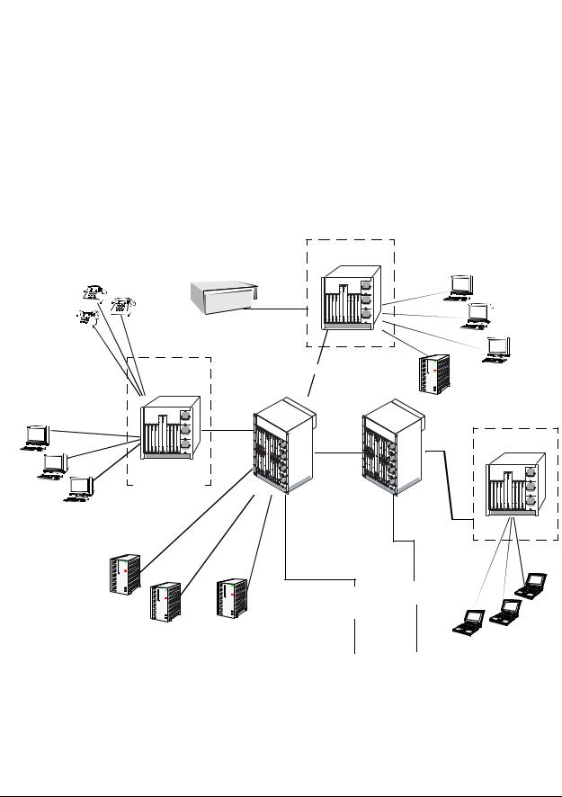
The following application example shows one of the many ways OmniSwitch 9000 switches can be used in an Enterprise network setting:
•Core Switch. In this example, an OS9800 is used as the core switch. Because the example network has a high-speed Gigabit Ethernet or 10-gigabit Ethernet backbone, the Network Interface (NI) cards in the chassis will be comprised mainly of Gigabit Ethernet or 10-gigabit Ethernet Network Interface (GNI, XNI) modules. The core switch connects to wiring closet switches as well as the company server farm.
•Wiring Closet Switches. The switches in wiring closets 1, 2, and 3 must contain some GNI/XNI modules in order to link to the Gigabit Ethernet/10-gigabit Ethernet core switch. However, in most cases, these switches will largely be comprised of Gigabit Ethernet Network Interface (GNI) modules. GNI modules support either 10/100/1000 (copper) or 100/1000 (fiber) Gigabit Ethernet connections. These Ethernet ports connect to various network devices, such as workstations, IP phones, and servers.
Wiring Closet 2
IP Phones |
|
OmniPCX |
|
|
|
|
|
|
|
|
Data |
|
|
100BaseTX |
Workstations |
|
|
10/100 |
|
|
10/100 |
|
|
|
|
|
|
Gigabit/10-gigabit |
|
|
|
Server |
|
Gigabit/ |
|
|
10-gigabit |
|
10/100 |
10-gigabit |
Wiring Closet 3 |
|
|
|
|
Core |
|
|
|
Data |
Wiring Closet 1 |
Switch |
|
|
|
Workstations |
|
|
|
|
|
WebView |
|
|
|
|
|
|
|
|
Gigabit/10-gigabit |
|
|
|
|
Gigabit |
|
|
|
|
|
|
Gigabit |
10/100 |
|
|
Gigabit |
Ethernet |
|
||
|
Ethernet |
Backbone |
|
|
|
|
|
Backbone |
|
|
|
|
Oracle |
OmniVista |
|
|
Data |
|
Server Farm |
|
|
WebView |
Workstations |
page 1-2 |
OmniSwitch 9000 Series Hardware Users Guide June 2007 |

OmniSwitch 9000 Series |
Availability Features |
|
|
|
|
Availability Features
The switch provides a broad variety of Availability features. Availability features are hardware and software-based safeguards that help prevent the loss of data flow in the unlikely event of a subsystem failure. In addition, some Availability features allow you to maintain or replace hardware components without powering off your switch or interrupting switch operations. Combined, these features provide added resiliency and help ensure that your switch is consistently available for your day-to-day network operations.
Hardware-related Availability features include:
•Hardware Redundancy
•Smart Continuous Switching
•Software Rollback
•Hot Swapping
•Hardware Monitoring
•Power Checking Sequence
Information on software-related availability is provided in the OmniSwitch 6800/9000 Switch Management Guide and the OmniSwitch 6800/9000 Network Configuration Guide. Refer to the corresponding feature chapter (e.g., VRRP).
Hardware Redundancy
Hardware redundancy refers to backup hardware components. If primary hardware components fail or go offline for any reason, the redundant hardware automatically assumes the primary hardware functions (this is also referred to as failover). The following components offer redundancy:
•Chassis Management Modules (CMMs)
•Power Supplies
•Fan Units
•MAC EEPROM
Note. Redundancy is a key Availability feature; it is recommended that you install redundant hardware components in your switch whenever possible. However, CMM redundancy is not supported on the OS9600 switch because it contains only one CMM slot.
For detailed information on CMM redundancy, refer to Chapter 4, “Chassis Management Module (CMM).” For information on power supply and fan redundancy, refer to Chapter 2, “Chassis and Power Supplies.”
OmniSwitch 9000 Series Hardware Users Guide June 2007 |
page 1-3 |

Availability Features |
OmniSwitch 9000 Series |
|
|
|
|
Smart Continuous Switching
In redundant CMM configurations, the switch provides support for NIs during failover. In other words, if the primary CMM fails or goes offline for any reason, NI modules will continue data transmission and routing functions during the secondary CMM’s takeover process. This Availability feature is referred to as
Smart Continuous Switching.
Incoming Layer 2 packets will continue to be sent to the appropriate egress port during failover. Known routes will also be supported. (Note, however, that the NI cannot learn new routes without CMM support. Any new route information will be ignored.) Spanning Tree will continue handling BPDUs received on the switch ports, as well as port link up and down states. The Spanning Tree topology will not be disrupted.
Note. Smart Continuous Switching is designed to maintain data flow only during CMM failover and is not intended to support long-term data flow. If both the primary and secondary CMM modules go offline or are removed from the chassis, switch operations (including all NI support) will be disabled. However, smart continuous switching is not possible on the OS9600 switch because it contains only one CMM slot.
For more information on CMM redundancy and the failover process, refer to Chapter 4, “Chassis Management Module (CMM).”
Software Rollback
Software rollback (also referred to as image rollback) essentially allows the switch to return to a prior “last known good” version of software in the event of a system software problem. The CMM controls software rollback through its resilient directory structure design (i.e., /flash/working and /flash/certified).
For detailed information on the software rollback feature, as well as the switch’s /flash/working and /flash/certified directories, refer to the “Managing CMM Directory Contents” chapter in the Switch Management Guide.
page 1-4 |
OmniSwitch 9000 Series Hardware Users Guide June 2007 |

OmniSwitch 9000 Series |
Availability Features |
|
|
|
|
Hot Swapping
Hot swapping refers to the action of adding, removing, or replacing certain hardware components without powering off your switch and disrupting other components in the chassis. This feature greatly facilitates hardware upgrades and maintenance and also allows you to easily replace components in the unlikely event of hardware failure. The following hardware components can be hot swapped:
•Chassis Management Modules (CMMs)
•Gigabit Ethernet Network Interface modules (GNIs)
•10-gigabit Ethernet Network Interface modules (XNIs)
•Power supplies
•Fan tray
Hot Swapping Non-Redundant Management Modules and Power Supplies. If there is only one CMM or power supply installed in the chassis and either of these components is removed or replaced, all switch functions will stop until a replacement is installed. However, hot swapping is not possible on the OS9600 switch because it contains only one CMM slot.
Hot Swapping NI Modules. It is recommended that you hot swap NIs of the same type
(e.g., OS9-GNI-C24) whenever possible. Otherwise, the network configuration may be adversely affected.
For information on hot swapping CMMs, refer to Chapter 4, “Chassis Management Module (CMM).” For information on hot swapping NI modules, refer to Chapter 5, “Network Interface (NI) Modules.” For information on hot swapping power supplies and the fan tray, refer to Chapter 2, “Chassis and Power Supplies.”
Hardware Monitoring
Automatic Monitoring
Automatic monitoring refers to the switch’s built-in sensors that automatically monitor operations. The majority of automatic monitoring is provided by the CMM. If an error is detected (e.g., over-threshold temperature), the CMM immediately sends a trap to the user. The trap is displayed on the console in the form of a text error message. (In the case of an over-threshold temperature condition, the CMM displays an amber TEMP LED in addition to sending a trap.)
LEDs
LEDs, which provide visual status information, are provided on the CMM, NI, and power supply front panels. LEDs are used to indicate conditions, such as hardware and software status, temperature errors, link integrity, data flow, etc. For detailed LED descriptions, refer to the corresponding hardware component chapter (e.g., “Network Interface (NI) Modules”).
User-Driven Monitoring
User-driven hardware monitoring refers to CLI commands that are entered by the user in order to access the current status of hardware components. The user enters “show” commands that output information to the console. The Show commands for all the features are described in detail in the OmniSwitch CLI Reference Guide.
OmniSwitch 9000 Series Hardware Users Guide June 2007 |
page 1-5 |

Availability Features |
OmniSwitch 9000 Series |
|
|
|
|
Power Checking Sequence
The power checking sequence is another built-in Availability feature. This feature helps regulate power in the switch whenever the switch is booted or an NI module is installed in the chassis.
The sequence is a joint effort between the CMM, the NI modules, and the power supplies. During the boot sequence, the primary CMM automatically compares the power consumption required by installed NIs with the power available from the power supplies. If there is not adequate power to support all NIs, the CMM will power on only the supported number of NIs, starting from the first NI slot position.
Important. During the power checking sequence, CMMs receive priority and are always powered on. NI modules are then powered on sequentially by slot position. In other words, the NI in slot 1 is powered on, then slot 2, then slot 3, etc. For information on slot positions, refer to Chapter 2, “Chassis and Power Supplies.”
Installing a New NI into a Running Chassis
When an NI module is installed in the chassis, only a small portion of the circuitry is initially powered up. The CMM immediately reads the incoming module’s ID and determines how much power the module will require. If the number of power supplies installed in the chassis can provide sufficient power, the CMM turns on the incoming module. If the number of installed power supplies cannot provide sufficient power, the incoming NI will remain powered off.
page 1-6 |
OmniSwitch 9000 Series Hardware Users Guide June 2007 |
2 Chassis and Power
Supplies
The OmniSwitch 9000 switches are available in three chassis configurations—the 18-slot OmniSwitch 9800 (OS9800), the 10-slot OmniSwitch 9700 (OS9700), and the 5-slot OmniSwitch 9600 (OS9600). This chapter includes detailed information on each of these chassis types. The topics include:
•Technical specifications on page 2-7.
•Switch mounting information on page 2-12.
•Power supplies and power supply redundancy on page 2-16.
•Temperature management on page 2-33.
•Chassis fan tray on page 2-35.
•Monitoring the chassis components via the Command Line Interface (CLI) on page 2-21.
OmniSwitch |
9800 |
||
|
|
|
|
1 |
|
|
|
9 |
2 |
NI |
|
|
10 |
|
3 |
11 |
4 |
|
|
12 |
CMM |
|
|
A |
B
5 |
|
|
|
|
13 |
6 |
NI |
|
|
|
14 |
7 |
|
|
|
|
15 |
8 |
|
|
|
|
16 |
PWR |
|
|
|
|
PS2PS1 |
|
|
|
|
PS4PS3 |
OmniSwitch |
9700 |
|
A
1
2 |
NI |
3
4
CMM
B
|
PWR |
5 |
|
6 |
NI |
|
7 |
|
8 |
OmniSwitchOS9- |
9600 |
XNI-U2 |
|
OS9- |
|
GNI-C24 |
|
OS9600/OS9700- |
CMM |
OS9- |
XNI-U2 |
OS9- |
GNI-C24 |
OmniSwitch OS9600, OS9700, OS9800
Warning. Do NOT install white color OmniSwitch 7700/7800 CMMs or NI modules in an OmniSwitch 9000 Series chassis, or damage to the modules or chassis may occur.
OmniSwitch 9000 Series Hardware Users Guide June 2007 |
page 2-1 |

OmniSwitch 9800 |
Chassis and Power Supplies |
|
|
|
|
OmniSwitch 9800
The OmniSwitch 9800 is a high performance switch offering 16 slots for Gigabit Ethernet and/or 10-Giga- bit Ethernet Network Interface (NI) modules. An additional two slots are reserved for primary and redundant Chassis Management Modules (CMMs). The OmniSwitch 9800 supports a maximum of four power supplies.
Note. Power supply requirements are based on the number of NIs installed in the chassis. Refer to “Power Supplies” on page 2-16 for important information on power supplies and power supply redundancy.
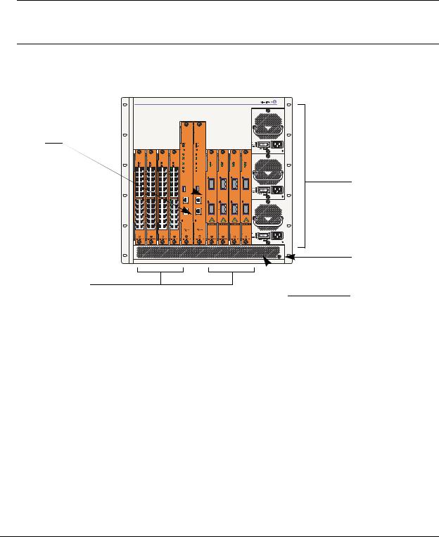
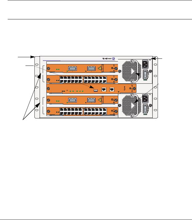
The following illustrations outline the major components of the OmniSwitch 9800 switch.
Network Interface
(NI) Modules
CMMs
Front Rack Mount
Flange
Network Interface
(NI) Modules
OmniSwitch 9800
|
|
NI |
|
|
CMM |
|
|
NI |
|
PWR |
1 |
2 |
3 |
4 |
|
|
5 |
6 |
7 |
8 |
PS1 |
A |
B |
PS2 |
||||||||
9 |
10 |
11 |
12 |
13 |
14 |
15 |
16 |
PS3 |
||
|
|
PS4 |
||||||||
C24-GNI-OS9 |
C24-GNI-OS9 |
C24-GNI-OS9 |
C24-GNI-OS9 |
CMM-OS9800 |
CMM-OS9800 |
C24-GNI-OS9 |
C24-GNI-OS9 |
C24-GNI-OS9 |
|
C24-GNI-OS9 |
|
|
|
|
OK1 |
OK1 |
|
|
|
|
|
|
|
|
|
OK2 |
OK2 |
|
|
|
|
|
|
|
|
|
CONTR OL |
CONTR OL |
|
|
|
|
|
|
|
|
|
FAB R IC |
FAB R IC |
|
|
|
|
|
|
|
|
|
TE MP |
TE MP |
|
|
|
|
|
|
|
|
|
FAN |
FAN |
|
|
|
|
|
|
|
|
|
PS U |
PS U |
|
|
|
|
|
C24-GNI-OS9 |
C24-GNI-OS9 |
C24-GNI-OS9 |
C24-GNI-OS9 |
US B |
US B |
U2-XNI-OS9 |
U2-XNI-OS9 |
U2-XNI-OS9 |
|
U2-XNI-OS9 |
|
|
|
|
CONSOLE/MODEM |
CONSOLE/MODEM |
|
|
|
|
|
|
|
|
|
E THE R NE T |
E THE R NE T |
|
|
|
|
|
|
1 |
1 |
1 |
1 |
L INK /ACT |
LINK /ACT |
|
|
|
2 |
2 |
2 |
2 |
OmniSwitch 9800 Front View
Front Rack Mount
Flange
Power Supplies
Grounding Lug
Air Intake Vent
page 2-2 |
OmniSwitch 9000 Series Hardware Users Guide June 2007 |
Chassis and Power Supplies |
OmniSwitch 9800 |
|
|
|
|
Front Rack Mount |
Front Rack Mount |
Flange |
Flange |
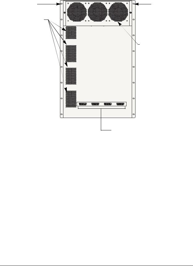
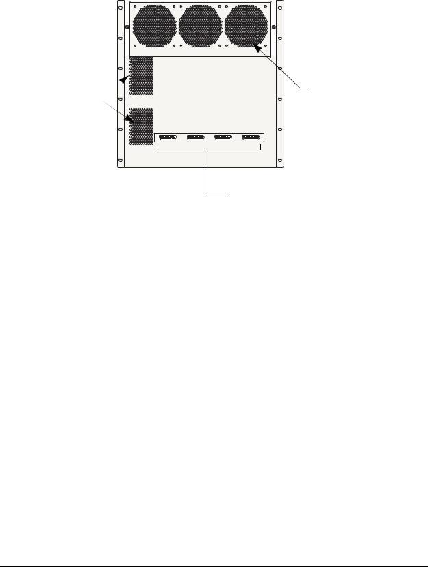
Airflow Exhaust Vents |
|
(for power supplies) |
|
Fan Tray (contains three fans)
for chassis temperature control and airflow exhaust
Connectors for inline power supply.
OmniSwitch 9800 Back View
OmniSwitch 9000 Series Hardware Users Guide June 2007 |
page 2-3 |

OmniSwitch 9800 Chassis and Power Supplies
OmniSwitch 9800 Technical Specifications
Total 10/100/1000 copper Ether- |
768 (Fully-populated with OS9-GNI-C48T modules. No other |
net ports available |
NI module types installed.) |
|
384 (Fully-populated with OS9-GNI-C24 and/or OS9-GNI-P24 |
|
modules. No other NI module types installed.) |
|
|
Total 1000BaseSX Ethernet |
384 (Fully-populated with OS9-GNI-U24 modules. No other |
ports available |
NI module types installed.) |
|
|
Total 10-Gigabit Ethernet ports |
32 (Fully-populated with OS9-XNI-U2 modules, with each |
available |
XNI containing two GBICs. No other NI modules installed.) |
|
96 (Fully-populated with OS9-XNI-U6 modules, with each |
|
XNI containing six GBICs. No other NI modules installed.) |
|
|
Total slots available for network |
16 |
interface (NI) modules |
|
|
|
Total slots available for CMMs |
2 |
|
|
Total bays for power supplies |
4 |
|
|
Power |
85 watts (approximate) |
|
|
|
|
OmniSwitch 9800 Chassis Dimensions
Overall Width (including rack-mount flanges) |
19 |
1/8 inches |
|
|
|
Chassis Width (rack-mount flanges not included) |
17 |
9/16 inches |
|
|
|
Height |
29 |
3/4 inches |
|
|
|
Height (rack units) |
17 |
RU |
|
|
|
Overall Depth (including required fan tray) |
17 |
5/16 inches |
|
|
|
Chassis Depth (fan tray not included) |
14 |
3/4 inches |
|
|
|
page 2-4 |
OmniSwitch 9000 Series Hardware Users Guide June 2007 |
Chassis and Power Supplies |
OmniSwitch 9700 |
|
|
|
|
OmniSwitch 9700
The OmniSwitch 9700 is a high performance switch offering eight slots for Gigabit Ethernet and/or 10gigabit Ethernet Network Interface (NI) modules. Additional two slots are reserved for primary and redundant Chassis Management Modules (CMMs). The OmniSwitch 9700 supports a maximum of three power supplies.
Note. Power supply requirements are based on the number of NIs installed in the chassis. Refer to “Power Supplies” on page 2-16 for important information on power supplies and power supply redundancy.
The following illustrations outline the major components of the OmniSwitch 9700 switch.
Front Rack Mount 

Flange
CMMs
OmniSwitch 9700
C24-GNI-OS9 |
C24-GNI-OS9 |
C24-GNI-OS9 |
C24-GNI-OS9 |
CMM-OS9600/OS9700 |
CMM-OS9600/OS9700 |
|
|
|
CONTROL |
U2-XNI-OS9 |
U2-XNI-OS9 |
U2-XNI-OS9 |
U2-XNI-OS9 |
||||
|
|
|
|
CONTROL |
|
|
|
|
|
|
|
|
FABRIC |
FABRIC |
|
|
|
TEMP |
TEMP |
FAN |
FAN |
PSU |
PSU |
|
LINK/ACT |
LINK/ACT |
LINK/ACT |
LINK/ACT |
USB |
USB |
|
|
|
COSOLE/MODEM |
COSOLE/MODEM |
|
|
|
|
LINK/ACT |
LINK/ACT |
LINK/ACT |
LINK/ACT |
ETHERNET |
ETHERNET |
|
|
|
LINK/ACT |
LINK/ACT |
|
|
|
Network Interface
(NI) Modules
 Front Rack Mount
Flange
Power Supplies
Grounding Lug
Air Intake Vent
OmniSwitch 9700 Front View
OmniSwitch 9000 Series Hardware Users Guide June 2007 |
page 2-5 |
OmniSwitch 9700 |
|
|
|
|
|
|
|
Chassis and Power Supplies |
||
|
|
|
|
|
|
|
|
|
|
|
|
|
|
|
|
|
|
|
|
|
|
|
|
|
|
|
|
|
|
|
|
|
|
|
|
|
|
|
|
|
|
|
|
|
|
|
|
|
|
|
|
|
|
|
|
|
|
|
|
|
|
|
|
|
|
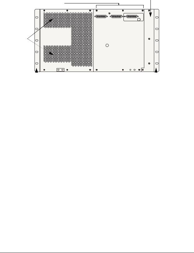
Airflow Exhaust Vents  (for power supplies)
Front Rack Mount 
Flange
Fan Tray (contains three fans)
for chassis temperature control and airflow exhaust
 Front Rack Mount
Flange
Connectors reserved for use with inline power supply.
OmniSwitch 9700 Back View
page 2-6 |
OmniSwitch 9000 Series Hardware Users Guide June 2007 |

Chassis and Power Supplies OmniSwitch 9700
OmniSwitch 9700 Technical Specifications
Total 10/100/1000 copper Ether- |
384 (Fully-populated with OS9-GNI-C24 and/or OS9-GNI-P24 |
net ports available |
modules. No other NI module types installed.) |
|
|
Total 1000Base SX fiber Ether- |
192 (Fully-populated with OS9-GNI-U24 modules. No other |
net ports available |
NI module types installed.) |
|
|
Total 10-Gigabit Ethernet ports |
16 (Fully-populated with OS9-XNI-U2 modules, with each |
available |
XNI containing two XFPs. No other NI modules installed.) |
|
48 (Fully-populated with OS9-XNI-U6 modules, with each |
|
XNI containing six XFPs. No other NI modules installed.) |
|
|
Total slots for network interface |
8 |
(NI) modules |
|
|
|
Total slots for CMM |
2 |
|
|
Total bays for power supplies |
3 |
|
|
Power |
50 W (approximate) |
|
|
OmniSwitch 9700 Chassis Dimensions
Overall Width (including rack-mount flanges) |
19 |
1/8 inches |
|
|
|
Chassis Width (rack-mount flanges not included) |
17 |
9/16 inches |
|
|
|
Height |
19 |
1/4 inches |
|
|
|
Height (rack units) |
11 RU |
|
|
|
|
Overall Depth (including required fan tray) |
17 |
5/16 inches |
|
|
|
Chassis Depth (fan tray not included) |
14 3/4 inches |
|
|
|
|
OmniSwitch 9000 Series Hardware Users Guide June 2007 |
page 2-7 |
OmniSwitch 9600 |
Chassis and Power Supplies |
|
|
|
|
OmniSwitch 9600
The OmniSwitch 9600 is a high performance switch offering four slots for Gigabit Ethernet and/or
10 gigabit Ethernet Network Interface (NI) modules. An additional one slot is reserved for the primary Chassis Management Module (CMM). The OmniSwitch 9600 supports a maximum of two load sharing power supplies on the front panel and there are optional power connectors, which consist of three DB-25 connectors mounted on the rear panel of the chassis for PoE applications. Either OS9-IP-SHELF or 360W/510W power supplies can be used. The first two connectors support OS9-IP-SHELF power supplies and the third connector supports 360W/510W power supplies.
Note. Power supply requirements are based on the number of NIs installed in the chassis. Refer to “Power Supplies” on page 2-16 for important information on power supplies and power supply redundancy.
The following illustrations outline the major components of the OmniSwitch 9600 switch:
Front Rack |
|
|
|
|
|
|
|
|
|
|
|
|
|
|
|
Mount |
|
|
|
|
|
|
|
|
|
|
|
|
|
|
Front Rack- |
Flange |
|
|
|
|
|
|
|
|
|
|
|
|
|
|
|
|
|
|
|
|
|
|
|
|
|
|
|
|
|
Mount Flange |
|
OmniSwitch 9600 |
|
|
|
|
|
|
|
|
|
|
|
|
|||
CMM |
|
|
|
|
|
|
|
|
|
|
|
|
|
|
|
OS9-XNI-U2 |
|
|
|
|
|
|
|
|
|
|
|
|
|
|
|
O K 1 |
OK2 |
|
LINK/ACT |
|
|
|
|
LINK/ACT |
|
|
|
|
|
|
|
1 |
|
|
|
|
|
|
|
|
|
|
|
||||
NI |
|
|
|
|
|
|
|
|
|
|
|
|
|
|
|
|
OS9-GNI-C24 |
|
|
|
|
|
|
|
|
|
|
|
|
|
|
2 |
O K 1 |
OK2 |
|
|
|
|
|
|
|
|
|
|
|
|
Power Supplies |
|
|
|
|
|
|
|
|
|
|
|
|
AC OK |
DC OK |
OVER TEMP |
|
|
OS9600/OS9700-CMM |
|
|
|
|
|
|
|
|
|
|
|
|
||
|
|
|
|
|
|
|
|
COSOLE/MODEM |
|
|
|
|
|
||
CMM |
|
O K 1 |
OK2 |
CONTROL |
FABRIC |
TEMP |
FAN |
PSU |
USB |
ETHERNET |
LINK/ACT |
|
|
|
|
|
OS9-XNI-U2 |
|
|
|
|
|
|
|
|
|
|
|
|
|
|
3 |
O K 1 |
OK2 |
|
LINK/ACT |
|
|
|
|
LINK/ACT |
|
|
|
|
|
|
NI |
|
|
|
|
|
|
|
|
|
|
|
|
|
|
|
|
OS9-GNI-C24 |
|
|
|
|
|
|
|
|
|
|
|
|
|
|
4 |
O K 1 |
OK2 |
|
|
|
|
|
|
|
|
|
|
|
|
|
|
|
|
|
|
|
|
|
|
|
|
|
AC OK |
DC OK |
OVER TEMP |
|
Network
Interface (NI) Modules
OmniSwitch 9600 Front View
page 2-8 |
OmniSwitch 9000 Series Hardware Users Guide June 2007 |
Chassis and Power Supplies |
OmniSwitch 9600 |
|
|
|
|
Fan Tray (contains four fans)
for chassis temperature Connectors reserved for use with inline control and airflow exhaust
power supply.
Airflow exhaust vents (for power supplies)
Front |
|
rack mount |
Front rack |
|
mount flange |
|
|
||||
flange |
|
|
|
||
|
|
|
OmniSwitch 9600 Back View |
||
OmniSwitch 9000 Series Hardware Users Guide June 2007 |
page 2-9 |

OmniSwitch 9600 Chassis and Power Supplies
OmniSwitch 9600 Technical Specifications
Total 10/100/1000 copper Ether- |
192 (Fully-populated with OS9-GNI-C24 and/or OS9-GNI-P24 |
|
net ports available |
modules. No other NI module types installed.) |
|
|
|
|
Total 1000Base SX fiber Ether- |
96 (Fully-populated with OS9-GNI-U24 modules. No other NI |
|
net ports available |
module types installed.) |
|
|
|
|
Total 10-Gigabit Ethernet ports |
8 (Fully-populated with OS9-XNI-U2 modules, with each XNI |
|
available |
containing two XFPs. No other NI modules installed.) |
|
|
24 (Fully-populated with OS9-XNI-U6 modules, with each |
|
|
XNI containing six XFPs. No other NI modules installed.) |
|
|
|
|
Total slots for network interface |
4 |
|
(NI) modules |
|
|
|
|
|
Total slots for CMM |
1 |
|
|
|
|
Total bays for power supplies |
2 |
|
|
|
|
Power |
50 W (approximate) |
|
|
|
|
|
|
|
OmniSwitch 9600 Chassis Dimensions |
||
|
|
|
Width |
19 inches |
|
|
|
|
Height |
9.575 inches |
|
|
|
|
Depth |
14.432 inches |
|
|
|
|
page 2-10 |
OmniSwitch 9000 Series Hardware Users Guide June 2007 |
Loading...