


 Loading...
Part No. 060181-10, Rev. C
April 2004
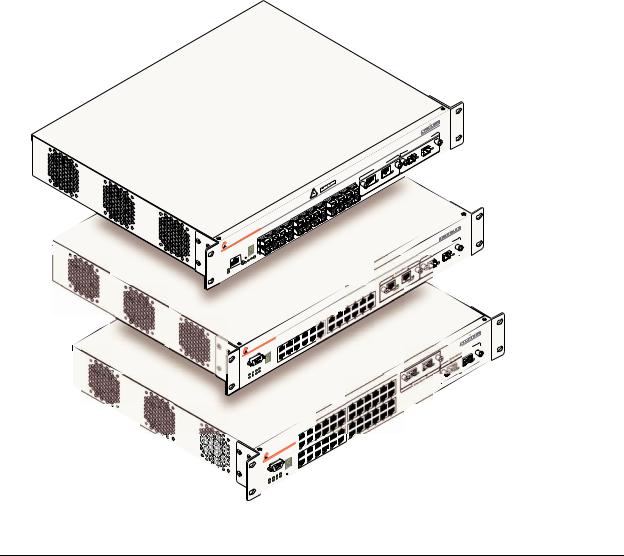
OmniSwitch 6624/6648
Hardware Users Guide

This user guide documents OmniSwitch 6600 Series hardware, including chassis and associated components.
The specifications described in this guide are subject to change without notice.
Copyright © 2004 by Alcatel Internetworking, Inc. All rights reserved. This document may not be reproduced in whole or in part without the express written permission of Alcatel Internetworking, Inc.
Alcatel® and the Alcatel logo are registered trademarks of Alcatel. Xylan®, OmniSwitch®, OmniStack®, and Alcatel OmniVista® are registered trademarks of Alcatel Internetworking, Inc.
OmniAccess™, Omni Switch/Router™, PolicyView™, RouterView™, SwitchManager™, VoiceView™, WebView™, X-Cell™, X-Vision™, and the Xylan logo are trademarks of Alcatel Internetworking, Inc.
This OmniSwitch product contains components which may be covered by one or more of the following U.S. Patents:
•U.S. Patent No. 6,339,830
•U.S. Patent No. 6,070,243
•U.S. Patent No. 6,061,368
•U.S. Patent No. 5,394,402
•U.S. Patent No. 6,047,024
•U.S. Patent No. 6,314,106
•U.S. Patent No. 6,542,507
26801 West Agoura Road
Calabasas, CA 91301
(818) 880-3500 FAX (818) 880-3505 info@ind.alcatel.com
US Customer Support—(800) 995-2696 International Customer Support—(818) 878-4507 Internet—http://eservice.ind.alcatel.com
ii |
OmniSwitch 6600 Series Hardware Users Guide April 2004 |

Contents
|
About This Guide ......................................................................................................... |
vii |
|
Supported Platforms ......................................................................................................... |
vii |
|
Who Should Read this Manual? ...................................................................................... |
viii |
|
When Should I Read this Manual? .................................................................................. |
viii |
|
What is in this Manual? ................................................................................................... |
viii |
|
What is Not in this Manual? ............................................................................................ |
viii |
|
How is the Information Organized? .................................................................................. |
ix |
|
Documentation Roadmap .................................................................................................. |
ix |
|
Related Documentation ..................................................................................................... |
xi |
|
User Manual CD .............................................................................................................. |
xii |
|
Technical Support ............................................................................................................ |
xii |
Chapter 1 |
OmniSwitch 6600 Series ........................................................................................... |
1-1 |
|
Stand-Alone and Stacked Configurations ....................................................................... |
1-2 |
|
Stand-Alone .............................................................................................................. |
1-2 |
|
Stacked Configurations ............................................................................................ |
1-2 |
|
Availability Features ....................................................................................................... |
1-3 |
|
Smart Continuous Switching .................................................................................... |
1-3 |
|
Software Rollback .................................................................................................... |
1-4 |
|
Hot Swapping ........................................................................................................... |
1-4 |
|
Hardware Monitoring ............................................................................................... |
1-4 |
|
Port and Fabric Capacities .............................................................................................. |
1-5 |
|
Application Examples ..................................................................................................... |
1-6 |
|
Single Office Building with 1000 Users ........................................................... |
1-6 |
|
Medium Campus with 1500 Users .................................................................... |
1-7 |
Chapter 2 |
OmniSwitch 6600 Series Chassis and Hardware Components ..................... |
2-1 |
|
OmniSwitch 6624 ............................................................................................................ |
2-3 |
|
OmniSwitch 6600-U24 ................................................................................................... |
2-5 |
|
OmniSwitch 6648 ............................................................................................................ |
2-9 |
|
Status LEDs ................................................................................................................... |
2-11 |
|
Rear Panel ..................................................................................................................... |
2-12 |
OmniSwitch 6600 Series Hardware Users Guide April 2004 |
iii |

|
Contents |
|
|
|
|
Mounting the Switch ..................................................................................................... |
2-13 |
Airflow Considerations .......................................................................................... |
2-13 |
Installation Options ................................................................................................ |
2-14 |
Installing the Switch on a Tabletop or Bench ................................................. |
2-14 |
Rack-Mounting the Switch .............................................................................. |
2-14 |
Rack Mounting Stacked Configurations ......................................................... |
2-16 |
Power Cords .................................................................................................................. |
2-17 |
Grounding the Chassis .................................................................................................. |
2-17 |
Back Up Power Supply ................................................................................................. |
2-18 |
Power Supply Redundancy .................................................................................... |
2-18 |
Redundant AC Circuit Recommendation ........................................................ |
2-19 |
Installing a Back Up Power Supply ....................................................................... |
2-20 |
Removing a Back Up Power Supply ...................................................................... |
2-22 |
Blank Cover Panel Requirement ............................................................................ |
2-23 |
Viewing Primary and Back Up Power Supply Status ............................................ |
2-23 |
Viewing Power Supply Status for Stacked Configurations ................................... |
2-24 |
A Slot Number is Specified ............................................................................. |
2-24 |
No Slot Number is Specified ........................................................................... |
2-24 |
Gigabit Ethernet Uplink Modules ................................................................................. |
2-25 |
OS6600-GNI-U2 .................................................................................................... |
2-25 |
OS6600-GNI-C2 .................................................................................................... |
2-27 |
Stacking Module .................................................................................................... |
2-28 |
Installing Uplink and Stacking Modules ....................................................................... |
2-29 |
Removing Uplink and Stacking Modules ..................................................................... |
2-31 |
Blank Cover Panel Requirement ............................................................................ |
2-32 |
Mini Gigabit Interface Converters (MiniGBICs) .......................................................... |
2-33 |
MiniGBIC Specifications ....................................................................................... |
2-34 |
Installing MiniGBICs .................................................................................................... |
2-35 |
Removing MiniGBICs .................................................................................................. |
2-36 |
100 Mbps SFPs (OS6600-U24) .................................................................................... |
2-37 |
100 Mbps SFP Specifications ............................................................................ |
2-38 |
Installing SFPs (OS6600-U24) ..................................................................................... |
2-40 |
Removing SFPs (OS6600-U24) .................................................................................... |
2-41 |
Temperature Management ............................................................................................ |
2-42 |
Viewing Chassis Temperature Status ..................................................................... |
2-42 |
Viewing Temperature Status for Stacked Configurations ...................................... |
2-43 |
A Slot Number is Specified ............................................................................. |
2-43 |
No Slot Number is Specified ........................................................................... |
2-43 |
Temperature Errors ................................................................................................ |
2-44 |
Warning Threshold .......................................................................................... |
2-44 |
Danger Threshold ............................................................................................ |
2-44 |
Viewing Fan Status ................................................................................................ |
2-45 |
Viewing Fan Status for Stacked Configurations .................................................... |
2-45 |
A Slot Number is Specified ............................................................................. |
2-45 |
No Slot Number is Specified ........................................................................... |
2-46 |
iv |
OmniSwitch 6600 Series Hardware Users Guide April 2004 |

Contents
|
|
|
|
|
|
|
......................................................................................................Chassis Airflow |
2-47 |
|
Blank Cover Panels ......................................................................................... |
2-48 |
|
Pinouts ........................................................................................................................... |
2-49 |
|
Console Port .................................................................................................................. |
2-51 |
|
Serial Connection to the Console Port ............................................................. |
2-51 |
|
Viewing Basic Chassis Information .............................................................................. |
2-53 |
|
Managing MAC Addresses on the Switch .................................................................... |
2-59 |
|
MAC Range Guidelines ......................................................................................... |
2-59 |
|
OmniSwitch 6600 Series MAC Range Specifications ........................................... |
2-59 |
|
Base Chassis MAC Address as Unique Identifier .................................................. |
2-60 |
|
Determining Current MAC Address Allocation on the Switch ............................. |
2-60 |
|
Base Chassis MAC Address in Stacked Configurations ........................................ |
2-60 |
Chapter 3 |
Managing OmniSwitch 6600 Series Stacks ........................................................ |
3-1 |
|
In This Chapter ................................................................................................................ |
3-1 |
|
Specifications and Default Values .................................................................................. |
3-2 |
|
Stack Overview ............................................................................................................... |
3-3 |
|
Stacking Resiliency and Redundancy ...................................................................... |
3-4 |
|
Slot Numbers within a Stack .................................................................................... |
3-4 |
|
CMM Roles in a Stack ............................................................................................. |
3-5 |
|
CMM Role Redundancy .................................................................................... |
3-5 |
|
CLI Commands Supported on Both the Primary and Secondary Role |
|
|
Switches ............................................................................................................ |
3-6 |
|
Setting Up a Stacked Configuration ................................................................................ |
3-8 |
|
Assigning Slot Numbers ........................................................................................... |
3-8 |
|
Slot Numbering Example ................................................................................ |
3-10 |
|
Connecting Cables to Stacking Ports ..................................................................... |
3-11 |
|
Redundant Stack Connection .......................................................................... |
3-13 |
|
Booting the Stack ................................................................................................... |
3-14 |
|
Verifying Slot Number Assignments .............................................................. |
3-14 |
|
Verifying Primary and Secondary Status for the Stack ................................... |
3-14 |
|
Managing Switches in a Stack ...................................................................................... |
3-16 |
|
Reloading a Switch with a Primary or Secondary CMM Role .............................. |
3-16 |
|
Synchronizing Switches in a Stack ........................................................................ |
3-17 |
|
Restoring Switch Redundancy ............................................................................... |
3-17 |
|
Changing the Secondary CMM Role to Primary ................................................... |
3-18 |
|
Resetting All Switches in a Stack .......................................................................... |
3-18 |
|
Monitoring Stacks ......................................................................................................... |
3-19 |
|
Monitoring Stack Topology ................................................................................... |
3-19 |
OmniSwitch 6600 Series Hardware Users Guide April 2004 |
v |

|
|
Contents |
|
|
|
|
|
|
Appendix A |
Regulatory Compliance and Safety Information ............................................. |
A-1 |
|
Declaration of Conformity: CE Mark ............................................................................ |
A-1 |
|
Standards Compliance .................................................................................................... |
A-2 |
|
FCC Class A, Part 15 .............................................................................................. |
A-3 |
|
Canada Class A Statement ...................................................................................... |
A-3 |
|
JATE ........................................................................................................................ |
A-3 |
|
CISPR22 Class A warning ...................................................................................... |
A-3 |
|
VCCI ....................................................................................................................... |
A-4 |
|
Class A Warning for Taiwan and Other Chinese Markets ...................................... |
A-4 |
|
Translated Safety Warnings ........................................................................................... |
A-5 |
|
Chassis Lifting Warning ................................................................................... |
A-5 |
|
Blank Panels Warning ...................................................................................... |
A-5 |
|
Electrical Storm Warning ................................................................................. |
A-5 |
|
Installation Warning ......................................................................................... |
A-6 |
|
Invisible Laser Radiation Warning ................................................................... |
A-6 |
|
Lithium Battery Warning ................................................................................. |
A-7 |
|
Operating Voltage Warning ............................................................................. |
A-7 |
|
Power Disconnection Warning ......................................................................... |
A-8 |
|
Proper Earthing Requirement Warning ............................................................ |
A-8 |
|
Read Important Safety Information Warning ................................................... |
A-9 |
|
Restricted Access Location Warning ............................................................... |
A-9 |
|
Wrist Strap Warning ....................................................................................... |
A-10 |
|
Index ...................................................................................................................... |
Index-1 |
vi |
OmniSwitch 6600 Series Hardware Users Guide April 2004 |

About This Guide
This OmniSwitch 6660 Series Hardware Users Guide describes your switch hardware components and basic switch hardware procedures.
Supported Platforms
This information in this guide applies to the following products:
•OmniSwitch 6624
•OmniSwitch 6600-U24
•OmniSwitch 6648
OmniSwitch 6600 series switches are next generation enterprise edge/workgroup switches. The OmniSwitch 6624 offers 24 copper 10/100 ports, the 6648 offers 48 copper 10/100 ports, and the 6600U24 offers 24 fiber 100 ports.
In addition, OmniSwitch 6624/6600-U24/6648 switches have one expansion port that can be used for a Gigabit Ethernet uplink module and another expansion port that can be used for a Gigabit Ethernet uplink or a stacking module. The stacking ports on all OmniSwitch 6600 series switches allow two to eight OmniSwitch 6600 series switches to be configured as one virtual chassis known as a stack.
Unsupported Platforms
The information in this guide does not apply to the following products:
•OmniSwitch (original version with no numeric model name)
•OmniSwitch 7700
•OmniSwitch 7800
•OmniSwitch 8800
•Omni Switch/Router
•OmniStack
•OmniAccess
OmniSwitch 6600 Series Hardware Users Guide April 2004 |
page vii |

Who Should Read this Manual? |
About This Guide |
|
|
|
|
Who Should Read this Manual?
The audience for this users guide is network administrators and IT support personnel who need to configure, maintain, and monitor switches and routers in a live network. However, anyone wishing to gain knowledge on the OmniSwitch 6600 series hardware will benefit from the material in this guide.
When Should I Read this Manual?
Read this guide as soon as you are ready to familiarize yourself with your switch hardware components. You should have already stepped through the first login procedures and read the brief hardware overviews in the OmniSwitch 6600 series Getting Started Guide.
You should already be familiar with the very basics of the switch hardware, such as module LEDs and module installation procedures. This manual will help you understand your switch hardware components (chassis, cooling fans, power supplies, Gigabit uplink modules, stacking modules, backup power supplies) in greater depth.
What is in this Manual?
This users guide includes the following hardware-related information:
•Descriptions of stand-alone and stacked configurations.
•Descriptions of “Availability” features.
•Descriptions of chassis types (OS6624, OS6600-U24, and OS6648).
•Instructions for mounting chassis.
•Descriptions of hardware components (status LEDs, Gigabit uplink modules, stacking modules, backup power supplies, MiniGBICs)
•Managing stand-alone chassis.
•Setting up stacks.
•Managing stacks.
•Hardware-related Command Line Interface (CLI) commands
What is Not in this Manual?
The descriptive and procedural information in this manual focuses on switch hardware. It includes information on some CLI commands that pertain directly to hardware configuration, but it is not intended as a software users guide. There are several OmniSwitch 6600 series users guides that focus on switch software configuration. Consult those guides for detailed information and examples for configuring your switch software to operate in a live network environment. See “Documentation Roadmap” on page ix and “Related Documentation” on page xi for further information on software configuration guides available for your switch.
page viii |
OmniSwitch 6600 Series Hardware Users Guide April 2004 |

About This Guide |
How is the Information Organized? |
|
|
|
|
How is the Information Organized?
This users guide provides an overview of OmniSwitch 6600 series switches in the first chapter, an overview and procedures for setting up and managing OmniSwitch 6600 series switches in the second chapter, and an overview and procedures for setting up and managing stacks in the third chapter.
Documentation Roadmap
The OmniSwitch user documentation suite was designed to supply you with information at several critical junctures of the configuration process.The following section outlines a roadmap of the manuals that will help you at each stage of the configuration process. Under each stage, we point you to the manual or manuals that will be most helpful to you.
Stage 1: Using the Switch for the First Time
Pertinent Documentation: OmniSwitch 6600 Series Getting Started Guide
Release Notes
A hard-copy OmniSwitch 6600 Series Getting Started Guide is included with your switch; this guide provides all the information you need to get your switch up and running the first time. This guide provides information on unpacking the switch, rack mounting the switch, installing uplink and stacking modules, unlocking access control, setting the switch’s IP address, setting up a password, and setting up stacks. It also includes succinct overview information on fundamental aspects of the switch, such as hardware LEDs, the software directory structure, stacking, CLI conventions, and web-based management.
At this time you should also familiarize yourself with the Release Notes that accompanied your switch. This document includes important information on feature limitations that are not included in other user guides.
Stage 2: Gaining Familiarity with Basic Switch Functions
Pertinent Documentation: OmniSwitch 6600 Series Hardware Users Guide
OmniSwitch 6624/6648 Switch Management Guide
Once you have your switch up and running, you will want to begin investigating basic aspects of its hard ware and software. Information about switch hardware is provided in the OmniSwitch 6600 Series Hardware Users Guide. This guide provide specifications, illustrations, and descriptions of all hardware components–chassis, power supplies, uplink and stacking modules, and cooling fans. It also includes steps for common procedures, such as removing and installing switch modules.
The OmniSwitch 6624/6648 Switch Management Guide is the primary user guide for the basic software features on a single switch. This guide contains information on the switch directory structure, basic file and directory utilities, switch access security, SNMP, and web-based management. It is recommended that you read this guide before connecting your switch to the network.
OmniSwitch 6600 Series Hardware Users Guide April 2004 |
page ix |

Documentation Roadmap |
About This Guide |
|
|
|
|
Stage 3: Integrating the Switch Into a Network
Pertinent Documentation: OmniSwitch 6624/6648 Network Configuration Guide OmniSwitch 6624/6648 Advanced Routing Configuration Guide
When you are ready to connect your switch to the network, you will need to learn how the OmniSwitch implements fundamental software features, such as 802.1Q, VLANs, and Spanning Tree. The OmniSwitch 6624/6648 Network Configuration Guide contains overview information, procedures and examples on how standard networking technologies are configured in the OmniSwitch 6600 series.
The OmniSwitch 6624/6648 Advanced Routing Configuration Guide includes configuration information for networks using Open Shortest Path First (OSPF).
Anytime
The OmniSwitch CLI Reference Guide contains comprehensive information on all CLI commands supported by the switch. This guide includes syntax, default, usage, example, related CLI command, and CLI-to-MIB variable mapping information for all CLI commands supported by the switch. This guide can be consulted anytime during the configuration process to find detailed and specific information on each CLI command.
page x |
OmniSwitch 6600 Series Hardware Users Guide April 2004 |
About This Guide |
Related Documentation |
|
|
|
|
Related Documentation
The following are the titles and descriptions of all the OmniSwitch 6600 series user manuals:
•OmniSwitch 6600 Series Getting Started Guide
Describes the hardware and software procedures for getting an OmniSwitch 6600 series switch up and running. Also provides information on fundamental aspects of OmniSwitch software and stacking architecture.
•OmniSwitch 6600 Series Hardware Users Guide
Complete technical specifications and procedures for all OmniSwitch 6600 series chassis, power supplies, fans, and uplink and stacking modules.
•OmniSwitch CLI Reference Guide
Complete reference to all CLI commands supported on the OmniSwitch 6624, 6600-U24, 6648, 7700, 7800, and 8800. Includes syntax definitions, default values, examples, usage guidelines and CLI-to- MIB variable mappings.
•OmniSwitch 6624/6648 Switch Management Guide
Includes procedures for readying an individual switch for integration into a network. Topics include the software directory architecture, image rollback protections, authenticated switch access, managing switch files, system configuration, using SNMP, and using web management software (WebView).
•OmniSwitch 6624/6648 Network Configuration Guide
Includes network configuration procedures and descriptive information on all the major software features and protocols included in the base software package. Chapters cover Layer 2 information (Ethernet and VLAN configuration), Layer 3 information, security options (authenticated VLANs), Quality of Service (QoS), and link aggregation.
•OmniSwitch 6624/6648 Advanced Routing Configuration Guide
Includes network configuration procedures and descriptive information on all the software features and protocols included in the advanced routing software package. Chapters cover the Open Shortest Path First (OSPF) Protocol.
•Technical Tips, Field Notices
Includes information published by Alcatel’s Customer Support group.
•Release Notes
Includes critical Open Problem Reports, feature exceptions, and other important information on the features supported in the current release and any limitations to their support.
OmniSwitch 6600 Series Hardware Users Guide April 2004 |
page xi |

User Manual CD |
About This Guide |
|
|
|
|
User Manual CD
All user guides for the OmniSwitch 6600 series are included on the User Manual CD that accompanied your switch. This CD also includes user guides for other Alcatel data enterprise products. In addition, it contains a stand-alone version of the on-line help system that is embedded in the OmniVista network management application.
Besides the OmniVista documentation, all documentation on the User Manual CD is in PDF format and requires the Adobe Acrobat Reader program for viewing. Acrobat Reader freeware is available at www.adobe.com.
Note. In order to take advantage of the documentation CD’s global search feature, it is recommended that you select the option for searching PDF files before downloading Acrobat Reader freeware.
To verify that you are using Acrobat Reader with the global search option, look for the following button in the toolbar:
Note. When printing pages from the documentation PDFs, de-select Fit to Page if it is selected in your print dialog. Otherwise pages may print with slightly smaller margins.
Technical Support
An Alcatel service agreement brings your company the assurance of 7x24 no-excuses technical support. You’ll also receive regular software updates to maintain and maximize your Alcatel product’s features and functionality and on-site hardware replacement through our global network of highly qualified service delivery partners. Additionally, with 24-hour-a-day access to Alcatel’s Service and Support web page, you’ll be able to view and update any case (open or closed) that you have reported to Alcatel’s technical support, open a new case or access helpful release notes, technical bulletins, and manuals. For more information on Alcatel’s Service Programs, see our web page at www.ind.alcatel.com, call us at 1-800-995- 2696, or email us at support@ind.alcatel.com.
page xii |
OmniSwitch 6600 Series Hardware Users Guide April 2004 |
1 OmniSwitch 6600 Series
The OmniSwitch 6600 series switches consist of the OmniSwitch 6624 (OS6624), OmniSwitch 6600-U24 (OS6600-U24), and the OmniSwitch 6648 (OS6648). The OmniSwitch 6600 series switches are next generation enterprise edge/workgroup switches. These switches are based on the same software architecture as OmniSwitch 7000 and 8000 series switches (i.e., OS7700, OS7800, and OS8800) and are designed to meet the most stringent network requirements for mission-critical networks.
OmniSwitch 6600 series switches are optimized for voice and data integration and provide non-blocking multi-Gigabit Ethernet capacity. Additional features include Carrier-class intelligence, best of breed QoS, Carrier-class resiliency, network management, and advanced policy-based VLANs and security.
OmniSwitch 6600 series switches also support wirespeed Layer 2 and Layer 3 switching, industry-based standards, and a full array of reliability, redundancy and resiliency capabilities.
OmniSwitch 6600-U24
|
|
|
|
|
|
|
|
|
|
|
|
21 |
|
|
|
|
|
|
|
|
|
|
|
|
19 |
|
|
|
|
|
|
|
|
|
|
|
|
17 |
|
|
|
|
|
|
|
|
|
|
|
|
15 |
|
|
|
|
|
|
|
|
|
|
|
13 |
22 |
|
|
|
|
|
|
|
|
|
|
|
21 |
|
|
|
|
|
|
|
|
|
|
|
|
11 |
20 |
|
|
|
|
|
|
|
|
|
|
|
19 |
|
|
|
|
|
|
|
|
|
|
|
9 |
|
18 |
|
|
|
|
|
|
|
|
|
|
|
17 |
|
|
|
|
|
|
|
|
|
|
|
7 |
|
16 |
|
|
|
|
|
|
|
|
|
|
|
15 |
|
|
|
|
|
|
|
|
|
|
24 |
5 |
|
14 |
|
|
|
|
|
|
|
00 |
-U |
13 |
|
||
|
|
|
|
|
66 |
|
3 |
12 |
|
|||
|
|
|
|
|
|
|
11 |
|
||||
|
|
|
|
|
|
|
|
|
10 |
|
||
|
|
|
|
itch |
|
|
|
1 |
9 |
|
||
|
|
niS |
w |
|
|
|
|
|
|
|||
|
m |
|
|
|
|
|
|
|
8 |
|
|
|
O |
|
|
|
|
|
|
|
|
|
6 |
|
|
|
|
|
|
|
|
|
|
|
|
5 |
|
|
|
|
|
|
|
|
|
|
|
|
4 |
|
|
|
|
|
|
|
|
|
|
2 |
3 |
|
|
|
|
|
NSO |
LE |
|
SEL |
|
|
1 |
2 |
|
|
|
|
CO |
|
|
|
|
|
|
|
||||
|
|
|
|
|
|
|
TEMP |
|
|
|
|
|
|
|
|
|
1 |
|
|
FAN |
|
|
|
|
|
|
|
|
|
PS |
|
SEC |
|
|
|
|
|
|
|
|
|
|
|
PRI |
|
|
|
|
|
|
|
OK1 |
|
|
|
PS2 |
|
|
|
|
|
|
|
|
|
|
|
|
|
|
|
|
|
|
|
|
|
OK2 |
|
|
|
|
|
|
|
|
|
|
|
|
|
|
NSIO |
N |
26 |
|
EXPA |
|
|
|
|
|
|
|
|
|
25 |
|
|
ACT |
|
|
|
|
|
|
|
|
|
LINK/ |
23 |
ACT |
|
|
|
LINK/ |
|
|
|
|
|
24 |
|
|
|
|
24 |
|
|
|
23 |
|
|
|
|
|
|
|
|
KIN |
G |
|
|
N/S |
TAC |
28 |
|
|
SIO |
|
|
|
|
PAN |
|
|
|
|
|
|
|
|
|
|
|
EX27 |
|
|
|
|
ACT |
|
|
|
|
|
LINK/ |
|
/ACT |
|
|
|
|
LINK |
|
|
|
|
|
|
|
|
|
TAC |
KIN |
|
|
|
N/S |
28 |
|
|
|
SIO |
|
|
|
EX |
PAN |
|
|
|
/ACT |
|
|
|
|
||
|
|
|
|
|
LINK |
|
LINK/ |
ACT |
|
|
|
|
|
|
|
||
OmniSwitch 6624
|
|
|
|
|
|
|
|
9 |
|
|
|
|
|
|
|
|
7 |
|
|
|
|
|
6 |
62 |
4 |
5 |
|
|
|
|
|
|
3 |
||
|
|
niS |
w |
itch |
|
1 |
10 |
|
O |
m |
|
|
|
|
8 |
||
|
|
|
|
|
|
|||
|
NSO |
LE |
|
|
|
|
6 |
|
CO |
|
|
|
|
|
|
||
|
|
|
|
|
|
|
4 |
|
|
|
|
|
|
|
|
2 |
|
|
|
PRI |
TEMP |
|
PS1 |
|
|
OK1 |
|
FAN |
|
|
SEC |
||
|
PS2 |
|
|
OK2 |
|
|
|
|
|
|
|
|
|
|
|
|
|
27 |
|
|
|
|
|
|
|
25 |
|
|
|
|
|
|
|
|
|
|
32 |
|
|
|
|
|
|
|
|
7 |
|
|
|
|
|
|
|
|
14 |
|
|
|
|
|
|
|
|
30 |
|
|
|
|
|
|
6624 |
|
5 |
|
|
|
|
|
|
3 |
12 |
|
OmniSwitch |
|
28 |
|
|||||
26 |
|
10 |
||||||
|
|
|
|
|
|
1 |
|
|
|
|
|
|
|
|
|
|
8 |
|
|
NSO |
LE |
|
|
6 |
||
|
CO |
|
|
|
|
|
||
|
|
|
|
|
|
4 |
|
|
|
|
|
|
|
|
2 |
|
|
|
|
|
PRI |
TEMP |
SEL |
|
|
|
|
PS1 |
|
|
|
|
|||
OK1 |
|
|
FAN |
|
|
|
||
|
|
SEC |
|
|
|
|||
OK2 |
PS2 |
|
|
|
|
|
|
|
|
|
|
|
|
|
|
|
|
OmniSwitch 6648
TA |
CK |
ING |
52 |
|
OmniSwitch 6624/6648 Hardware Users Guide April 2004 |
page 1-1 |

Stand-Alone and Stacked Configurations |
OmniSwitch 6600 Series |
|
|
|
|
Stand-Alone and Stacked Configurations
Stand-Alone
A stand-alone OmniSwitch 6600 series switch is ideal for small and medium-sized network edge applications, offering 24 or 48 10/100 ports, respectively. These switches provide support for enterprise-based devices, such as computer workstations or IP telephones.
A single OmniSwitch 6600 series switch also supports two Gigabit Ethernet uplinks for high-bandwidth connections to a backbone or server.
Stacked Configurations
In addition to working as individual, stand-alone switches, OmniSwitch 6600 series switches can also be linked together to form a single, high-density virtual chassis known as a stack.
Stacking switches provides scalability by allowing users to quickly and easily expand 10/100 port density. Twenty-four 10/100 ports are added for each OS6624 brought into the stack; twenty-four 100 ports are added for each OS6600-U24 brought into the stack; forty-eight 10/100 ports are added for each OS6648.
Up to eight switches can be stacked. OmniSwitch 6600 series switches can be mixed and matched in any combination within the stack. This provides a virtual chassis with a 10/100 or 100 capacity of up to 384 ports.
As with the stand-alone configuration, a stacked virtual chassis configuration provides Gigabit Ethernet uplinks to a backbone or server.
Note. For detailed information on stacking OmniSwitch 6600 series switches into a virtual chassis, refer to Chapter 3, “Managing OmniSwitch 6600 Series Stacks.”
Note on Terminology. In the user manuals provided with your switch, the terms switch, slot and NI (Network Interface) refer to individual OmniSwitch 6600 series units in standalone mode or within a stacked configuration. The term CMM (Chassis Management Module) refers to stacked OmniSwitch 6600 series units operating in primary or secondary CMM roles. (An OmniSwitch 6600 series switch operating in an idle CMM role would normally be referred to as a switch, slot, or, NI.)
page 1-2 |
OmniSwitch 6624/6648 Hardware Users Guide April 2004 |

OmniSwitch 6600 Series |
Availability Features |
|
|
|
|
Availability Features
The switch provides a broad variety of Availability features. Availability features are hardwareand software-based safeguards that help prevent the loss of data flow in the unlikely event of a subsystem failure. In addition, some Availability features allow you to maintain or replace hardware components without powering off your switch or interrupting switch operations. Combined, these features provide added resiliency and help ensure that your switch is consistently available for your day-to-day network operations.
Hardware-related Availability features include:
•Smart Continuous Switching
•Software Rollback
•Hot Swapping
•Hardware Monitoring
Smart Continuous Switching
In stacked configurations, one OmniSwitch 6600 series switch is designated as the primary “management module” for the stack. Because the stack can be thought of as a virtual chassis, the role of this primary management switch is to monitor and manage the functions of the stack.
Similar to chassis-based switches such as the OmniSwitch 7700 and Omniswitch 7800, the stack also allows users to assign an additional switch as a secondary management module. As with the OS7700 and OS7800, the stack’s secondary switch immediately takes over management functions in the event of a primary switch failure.
All other switches in the stack are considered idle, and act very much like Ethernet Network Interface (ENI) modules in OS7700 and OS7800 switches, in that they provide Ethernet ports for 10/100 traffic.
The stack provides support for all idle switches during primary-to-secondary failover. In other words, if the stack’s primary switch fails or goes offline for any reason, all idle switches will continue data transmission during the secondary switch’s takeover process. This Availability feature is referred to as Smart Continuous Switching.
Incoming Layer 2 packets will continue to be sent to the appropriate egress port during failover. Spanning Tree will continue handling BPDUs received on the switch ports, as well as port link up and down states. The Spanning Tree topology will not be disrupted.
Note. Smart Continuous Switching is designed to maintain data flow only during primary/secondary switch failover and is not intended to support long-term data flow. If both the primary and secondary switches in the stack go offline, switch operations (including all 10/100 support) will be disabled.
For more information on primary, secondary, and idle switches, as well as the failover process, refer to Chapter 3, “Managing OmniSwitch 6600 Series Stacks.”
OmniSwitch 6624/6648 Hardware Users Guide April 2004 |
page 1-3 |

Availability Features |
OmniSwitch 6600 Series |
|
|
|
|
Software Rollback
Software rollback (also referred to as image rollback) essentially allows the OmniSwitch 6600 series switches (in both standalone and stacked configurations) to return to a prior “last known good” version of software in the event of a system software problem. The switch controls software rollback through its resilient directory structure design (i.e., /flash/working and /flash/certified).
For detailed information on the software rollback feature, as well as the switch’s /flash/working and /flash/certified directories, refer to the “Managing CMM Directory Content” chapter in the OmniSwitch 6600 Series Switch Management Guide.
Hot Swapping
Hot swapping refers to the action of adding, removing, or replacing back up power supplies, as well as uplink modules and MiniGBICs, without powering off your switch and disrupting other components in the switch or stack. This feature greatly facilitates hardware upgrades and maintenance and also allows you to easily replace components in the unlikely event of hardware failure. The following hardware components can be hot swapped:
•OS66BPS-100A Back Up Power Supply
•OS6600-GNI-C2 Gigabit Ethernet Uplink Submodule
•OS6600-GNI-U2 Gigabit Ethernet Uplink Submodule
•MiniGBICs installed in the OS6600-GNI-U2 Gigabit Ethernet Uplink Submodule; MiniGBICs include:
-MiniGBIC-SX
-MiniGBIC-LX
-MiniGBIC-LH-70
Note. Stacking modules cannot be hot swapped at any time. For information on stacking modules, refer to
For instructions on hot swapping back up power supplies, uplink modules, and MiniGBICs, refer to Chapter 2, “OmniSwitch 6600 Series Chassis and Hardware Components.”
Hardware Monitoring
Automatic Monitoring
Automatic monitoring refers to the switch’s built-in sensors that automatically monitor operations. If an error is detected (e.g., over-threshold temperature), the switch immediately sends a trap to the user. The trap is displayed on the console in the form of a text error message. (In the case of an over-threshold temperature condition, the chassis displays an amber TEMP LED in addition to sending a trap.)
LEDs
LEDs, which provide visual status information, are provided on the chassis front panel. LEDs are used to indicate conditions such as hardware and software status, temperature errors, link integrity, data flow, etc. For detailed LED descriptions, refer to Chapter 2, “OmniSwitch 6600 Series Chassis and Hardware Components.”
page 1-4 |
OmniSwitch 6624/6648 Hardware Users Guide April 2004 |

OmniSwitch 6600 Series |
Port and Fabric Capacities |
|
|
|
|
User-Driven Monitoring
User-driven hardware monitoring refers to CLI commands that are entered by the user in order to access the current status of hardware components. The user enters “show” commands that output information to the console. Monitoring information for chassis components such as the optional back up power supply, chassis temperature sensor, and chassis fans is provided in Chapter 2, “OmniSwitch 6600 Series Chassis and Hardware Components.” Show commands for all features are described in detail in the OmniSwitch CLI Reference Guide.
Port and Fabric Capacities
OmniSwitch 6600 series switches offer 24 10/100 Ethernet ports, 24 100 Ethernet ports, or 48 10/100 Ethernet ports. The switches also offer expansion gigabit uplink and stacking ports. Refer to Chapter 2, “OmniSwitch 6600 Series Chassis and Hardware Components” for expansion port details.
OmniSwitch 6600 Series Fabric Capacities
OS6624/OS6600-U24 |
Up to 7.0 Gbps at full duplex; 14.0 Gbps aggregate |
|
|
OS6648 |
Up to 10.0 Gbps at full duplex; 20.0 Gbps aggregate |
|
|
OS6624/6600-U24 Throughput |
|
|
|
10/100Mbps Copper Ethernet ports |
Approximately 3.57 Mpps |
(OS6624 only) |
|
|
|
100Mbps Fiber Ethernet ports |
Approximately 3.57 Mpps |
(OS6600-U24 only) |
|
|
|
Gigabit Ethernet uplink ports |
Approximately 5.95 Mpps (stand-alone switches with four Gigabit |
|
Ethernet uplink modules installed) |
|
|
Total throughput |
Approximately 9.52 Mpps |
|
|
OS6648 Throughput |
|
|
|
10/100Mbps Ethernet ports |
Approximately 7.14 Mpps |
|
|
Gigabit Ethernet uplink ports |
Approximately 5.95 Mpps (stand-alone switches with four Gigabit |
|
Ethernet uplink modules installed) |
|
|
Total throughput |
Approximately 13.09 Mpps |
|
|
For detailed information on OmniSwitch 6600 series features, functions, and technical specifications, refer to Chapter 2, “OmniSwitch 6600 Series Chassis and Hardware Components” and Chapter 3, “Managing OmniSwitch 6600 Series Stacks.” For additional general information, including application examples, refer to the sections below.
OmniSwitch 6624/6648 Hardware Users Guide April 2004 |
page 1-5 |
Application Examples |
OmniSwitch 6600 Series |
|
|
|
|
Application Examples
The following application examples show two of the many ways OmniSwitch 6600 series switches can be used in an enterprise network setting.
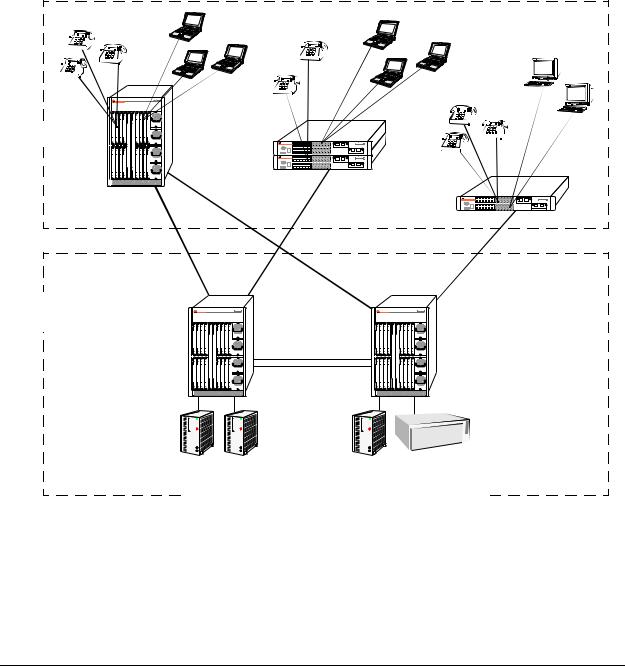
Single Office Building with 1000 Users
The following diagram shows converged voice and data applications, with 1000 users, in a single building enterprise environment. Edge devices consist of a mixture of PCs and IP telephones. In this example, a single OmniPCX 4400 in the core supports IP voice initiations and terminations. An OmniSwitch 7800 switch provides a port density of 1000 10/100 ports. The stackable OmniSwitch 6600 series configurations provide redundant and dual connectivity from the edge to the redundant backbone/core, in which the OmniSwitch 7800 core switches are used.
IP Phones |
IP Phones |
|
Gigabit |
Gigabit |
IP Phones |
|
|
|
Edge |
|
Gigabit |
|
|
Gigabit
Backbone
Data Center
Gigabit
Server Farm |
|
Server |
OmniPCX |
||||||||||||||||||||||||||||
|
|
|
|
|
|
|
|
|
|
|
|
|
|
|
|
|
|
|
|
|
|
|
|
|
|
|
|
|
|
|
|
page 1-6 |
OmniSwitch 6624/6648 Hardware Users Guide April 2004 |
OmniSwitch 6600 Series |
Application Examples |
|
|
|
|
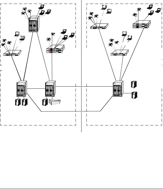
Medium Campus with 1500 Users
This example illustrates converged voice and data applications with 1500 users spread across two buildings in an enterprise campus. Edge devices consist of a mixture of PCs and IP telephones. And, like the previous example, a single OmniPCX 4400 in the core supports IP voice initiations and terminations.
In building number one, an OmniSwitch 7800 switch provides a port density of 1000 10/100 ports, and the stackable OmniSwitch 6600 series configurations provide redundant and dual connectivity from the edge to the redundant backbone/core. In building number two, the stackable OmniSwitch 6600 series configurations provide 500 ports for connectivity from the edge to the backbone/core.
IP Phones
10/100 |
10/100 |
10/100 |
IP Phones |
|
|
IP Phones


10/100 |
10/100 |
10/100 |
|
|
|
|
|
|
|
|
|
|
|
|
|
|
|
|
|
|
|
|
|
|
|
|
|
|
|
|
|
|
|
|
|
|
|
|
|
|
|
|
|
|
|
|
|
|
|
|
|
|
|
|
|
|
|
|
|
|
|
|
|
|
|
|
|
|
|
|
|
|
|
|
|
|
|
|
|
|
|
|
|
|
|
|
|
|
|
|
|
|
|
|
|
|
|
|
|
|
|
|
|
|
|
|
|
|
|
|
|
|
|
|
|
|
|
|
|
|
|
|
|
|
|
|
|
|
|
|
|
|
|
|
|
|
|
|
|
|
|
|
|
|
|
|
|
|
|
|
|
|
|
|
|
|
|
|
|
|
|
|
|
|
|
|
|
|
|
|
|
|
|
|
|
|
|
|
|
|
|
|
|
|
|
|
|
|
|
|
|
|
|
|
|
|
|
|
|
|
|
|
|
|
|
|
|
|
|
|
|
|
|
|
|
|
|
|
|
|
|
|
|
|
|
|
|
|
|
|
|
|
|
|
|
|
|
|
|
|
|
|
|
|
|
|
|
|
|
|
|
|
|
|
|
|
|
|
|
|
|
|
|
|
|
|
|
|
|
|
|
|
|
|
|
|
|
|
|
|
|
|
|
|
|
|
|
|
|
|
|
|
|
|
|
|
|
|
|
|
|
|
|
|
|
|
|
|
|
|
|
|
|
|
|
|
|
|
|
|
|
|
|
|
|
|
|
|
|
|
|
|
|
|
|
|
|
|
|
|
|
|
|
|
|
|
|
|
|
|
|
|
|
|
|
|
|
|
|
|
|
|
|
|
|
|
|
|
|
|
|
|
|
|
|
|
|
|
|
|
|
|
|
|
|
|
|
|
|
|
|
|
|
|
|
|
|
|
|
|
|
|
|
|
|
|
|
|
|
|
|
|
|
|
|
|
|
|
|
|
|
|
|
|
|
|
|
|
|
|
|
|
|
|
|
|
|
|
|
|
|
|
|
|
|
|
|
|
|
|
|
|
|
|
|
|
|
|
|
|
|
|
|
|
|
|
|
|
|
|
|
|
|
|
|
|
|
|
|
|
|
|
|
|
|
|
|
|
|
|
|
|
|
|
|
|
|
|
|
|
|
|
|
|
|
|
|
|
|
|
|
|
|
|
|
|
|
|
|
|
|
|
|
|
|
|
|
|
|
|
|
|
|
|
|
|
|
|
|
|
|
|
|
|
|
|
|
|
|
|
|
|
|
|
|
|
|
|
|
|
|
|
|
|
|
|
|
|
|
|
|
|
|
|
|
|
|
|
|
|
|
|
|
|
|
|
|
|
|
|
|
|
|
|
|
|
|
|
|
|
|
|
|
|
|
|
|
|
|
|
|
|
|
|
|
|
|
|
|
|
|
|
|
|
|
|
|
|
|
|
|
|
|
|
|
|
|
|
|
|
|
|
|
|
|
|
|
|
|
|
|
|
|
|
|
|
|
|
|
|
|
|
|
|
|
|
|
|
|
|
|
|
|
|
|
|
|
|
|
|
|
|
|
|
|
|
|
|
|
|
|
|
|
|
|
|
|
|
|
|
|
|
|
|
|
|
|
|
|
|
|
|
|
|
|
|
|
|
|
|
|
|
|
|
|
|
|
|
|
|
|
|
|
|
|
|
|
|
|
|
|
|
|
|
|
|
|
|
|
|
|
|
|
|
|
|
|
|
|
|
Edge |
|
|
|
|
|
|
|
|
|
|
|
|
|
|
|
|
|
|
|
|
|
|
|
|
|
|
|
|
|
|
|
|
|
|
|
|
|
|
|
|
Edge |
|||||||||
|
|
|
|
|
|
|
|
|
|
|
|
|
|
|
|
|
|
|
|
|
|
|
|
|
|
|
|
|
|
|
|
|
|
|
|
|
|
|
|
|||||||||||||||||||||||||||||||||||||||||||||||||||||||||||||
|
|
|
|
|
|
|
|
|
|
|
|
|
|
|
|
|
|
|
|
|
|
|
|
|
|
|
|
|
|
|
|
|
|
|
|
|
|
|
|
|
|
|
|
|
|
|
|
|
|
|
|
|
|
|
|
|
|
|
|
|
|
|
|
|
|
|
|
|
|
|
|
|
|
|
|
|
|
|
|
|
|
|
|
|
|
|
|
|
|
|
|
|
|
|
|
|
|
|
|
|
|
|
|
|
|
|
|
|
|
|
|
|
|
|
|
|
|
|
|
|
|
|
|
|
|
|
|
Gigabit |
|
|
|
|
|
|
|
|
|
|
|
|
|
|
|
|
Gigabit |
|
|
|
|
||||||||||||||||||||||||||||||||||||||||||||||||||||
|
|
|
|
|
|
|
|
|
|
|
|
|
|
|
|
|
|
|
|
|
|
|
|
|
|
|
|
|
|
|
|
|
|
|
|
|
|
|
|
|
|
|
|
|
|
|
|
|
|
|
|
|
|
|
|
|
|
|
|
|
|
|
|
|
|
|
|
|
|
|
|
|
|
|
|
|
|
|
|
|
|
|
|
|
|
|
|
|
|
|
|
|
|
|
|
|
|
|
|
|
|
|
|
|
|
|
|
|
|
|
|
|
|
|
|
|
|
|
|
|
|
|
|
|
|
|
|
|
|
|
|
|
|
|
|
|
|
|
|
|
|
|
|
|
|
|
|
|
|
|
|
|
|
|
|
|
|
|
|
|
|
|
|
|
|
|
|
|
|
|
|
|
|
|
|
|
|
|
|
|
|
|
|
|
|
|
|
|
|
|
|
|
|
|
|
|
|
|
|
|
|
|
|
|
|
|
|
|
|
|
|
|
|
|
|
|
|
|
|
|
|
|
|
|
|
|
|
|
|
|
|
|
|
|
|
|
|
|
|
|
|
|
|
|
|
|
|
|
|
|
|
|
|
|
|
|
|
|
|
|
|
|
|
|
|
|
|
|
|
|
|
|
|
|
|
|
|
|
|
|
|
|
|
|
|
|
|
|
|
|
|
|
|
|
|
|
|
|
|
|
|
|
|
|
|
|
|
|
|
|
|
|
|
|
|
|
|
|
|
|
|
|
|
|
|
|
|
|
|
|
|
|
|
|
|
|
|
|
|
|
|
|
|
|
|
|
|
|
|
|
|
|
|
|
|
|
|
|
|
|
|
|
|
|
|
|
|
|
|
|
|
|
|
|
|
|
|
|
|
|
|
|
|
|
|
|
|
|
|
|
|
|
|
|
|
|
|
|
|
|
|
|
|
|
|
|
|
|
|
|
|
|
|
|
|
|
|
|
|
|
|
|
|
|
|
|
|
|
|
|
|
|
|
|
|
|
|
|
|
|
|
|
|
|
|
|
|
|
|
|
|
|
|
|
|
|
|
|
|
|
|
|
|
|
|
|
|
|
|
|
|
|
|
|
|
|
|
|
|
|
|
|
|
|
|
|
|
|
|
|
|
|
|
|
|
|
|
|
|
|
|
|
|
|
|
|
|
|
|
|
|
|
|
|
|
|
|
|
|
|
|
|
|
|
|
|
|
|
|
|
|
|
|
|
|
|
|
|
|
|
|
|
|
|
|
|
|
|
|
|
|
|
|
|
|
|
|
|
|
|
|
|
|
|
|
|
|
|
|
|
|
|
|
|
|
|
|
|
|
|
|
|
|
|
|
|
|
|
|
|
|
|
|
|
|
|
|
|
|
|
|
|
|
|
|
|
|
|
|
|
|
|
|
|
|
|
|
|
|
|
|
|
|
|
|
|
|
|
|
|
|
|
|
|
|
|
|
|
|
|
|
|
|
|
|
|
|
|
|
|
|
|
|
|
|
|
|
|
|
|
|
|
|
|
|
|
|
|
|
|
|
|
|
|
|
|
|
|
|
|
|
|
|
|
|
|
|
|
|
|
|
|
|
|
|
|
|
|
|
|
|
|
|
|
|
|
|
|
|
|
|
|
|
|
|
|
|
|
|
|
|
|
|
|
|
|
|
|
|
|
|
|
|
|
|
|
|
|
|
|
|
|
|
|
|
|
|
|
|
|
|
|
|
|
|
|
|
|
|
|
|
|
|
|
|
|
|
|
|
|
|
|
|
|
|
|
|
|
|
|
|
|
|
|
|
|
|
|
|
|
|
|
|
|
|
|
|
|
|
|
|
|
|
|
|
|
|
|
|
|
|
|
|
|
|
|
|
|
|
|
|
|
|
|
|
|
|
|
|
|
|
|
|
|
|
|
|
|
|
|
|
|
|
|
|
|
|
|
|
|
|
|
|
|
|
|
|
|
|
|
|
|
|
|
|
|
|
|
|
|
|
|
|
|
|
|
|
|
|
|
|
|
|
|
|
|
|
|
|
|
|
|
|
|
|
|
|
|
|
|
|
|
|
|
|
|
|
|
Server Farm
OmniPCX |
Gigabit |
Server Farm |
|
Backbone |
Backbone |
Data Center |
Data Center |
Building Number One |
Building Number Two |
OmniSwitch 6624/6648 Hardware Users Guide April 2004 |
page 1-7 |

Application Examples |
OmniSwitch 6600 Series |
|
|
|
|
page 1-8 |
OmniSwitch 6624/6648 Hardware Users Guide April 2004 |
2 OmniSwitch 6600 Series
Chassis and Hardware
Components
OmniSwitch 6600 series switches are available in five stackable chassis configurations—the 24-port OmniSwitch 6624 (OS6624) and the OmniSwitch 6600-U24 (OS6600-U24) and the 48-port OmniSwitch 6648 (OS6648). This chapter includes detailed information on each of these chassis types. Topics include:
•OmniSwitch 6600 series chassis descriptions
•Technical specifications
•Switch mounting
•Back up power supply
•Gigabit Ethernet uplink and stacking modules
•MiniGBICs
•100 Mbps SFPs
•Temperature management
•Pinouts and console port specifications
•Monitoring switch status
•Base chassis MAC address
OmniSwitch 6600 Series Hardware Users Guide April 2004 |
page 2-1 |

OmniSwitch 6600 Series Chassis and Hardware Components
|
|
|
|
|
|
|
|
|
|
|
|
23 |
|
|
|
|
|
|
|
|
|
|
|
|
21 |
|
|
|
|
|
|
|
|
|
|
|
19 |
24 |
|
|
|
|
|
|
|
|
|
|
|
17 |
|
|
|
|
|
|
|
|
|
|
|
15 |
|
24 |
|
|
|
|
|
|
|
|
|
|
|
23 |
|
|
|
|
|
|
|
|
|
|
|
13 |
|
22 |
|
|
|
|
|
|
|
|
|
|
|
21 |
|
|
|
|
|
|
|
|
|
|
|
11 |
|
20 |
|
|
|
|
|
|
|
|
|
|
19 |
|
|
|
|
|
|
|
|
|
|
|
9 |
|
18 |
|
|
|
|
|
|
|
|
|
|
|
|
17 |
|
|
|
|
|
|
|
|
|
|
7 |
15 |
16 |
|
|
|
|
|
|
|
|
-U24 |
|
5 |
14 |
|
|
|
|
|
|
|
|
|
|
|
13 |
|
|
|
|
|
|
|
6600 |
|
3 |
12 |
|
|
|||
|
|
|
|
|
|
11 |
|
|
||||
|
|
|
tch |
|
|
|
1 |
9 |
10 |
|
|
|
|
|
|
|
|
|
|
|
|
|
|||
|
m |
niSwi |
|
|
|
|
|
8 |
|
|
|
|
O |
|
|
|
|
|
|
|
|
6 |
|
|
|
|
|
|
|
|
|
|
|
|
5 |
|
|
|
|
|
|
|
|
|
|
|
|
4 |
|
|
|
|
|
|
|
|
|
|
2 |
|
3 |
|
|
|
|
|
|
LE |
|
|
|
|
|
2 |
|
|
|
|
CO |
NSO |
|
SEL |
|
1 |
|
|
|
|
|
|
|
|
|
|
|
|
P |
|
|
|
|
|
|
|
|
|
1 |
|
|
FAN |
TEM |
|
|
|
|
|
|
|
|
PS |
|
SEC |
|
|
|
|
|
|
|
|
|
|
|
PRI |
|
|
|
|
|
|
|
|
OK1 |
|
|
PS2 |
|
|
|
|
|
|
|
|
|
|
|
|
|
|
|
|
|
|
|
|
|
|
OK2 |
|
|
|
|
|
|
|
|
|
|
|
|
|
|
NS |
IO |
N |
2 |
6 |
EX |
PA |
|
|
|
|
|
|
|
|
|
|
|
|
25 |
|
|
|
|
|
/ACT |
|
|
|
|
|
|
|
|
|
|
|
|
|
LINK |
CT |
|
|
|
|
|
|
K/A |
|
|
|
|
|
|
LIN |
|
|
|
|
|
|
|
|
|
|
|
|
CK |
IN |
G |
|
|
|
|
|
|
STA |
2 |
8 |
|
|
|
|
|
|
N/ |
|
|
|
||
|
|
NS |
IO |
|
|
|
|
|
|
EX |
PA |
|
|
|
|
|
|
|
|
|
|
|
|
|
|
|
/ACT |
||
2 |
7 |
|
|
|
|
|
|
|
|
|
|
|
|
|
|
|
|
|
LINK |
|
K/AC |
T |
OmniSwitch 6600-U24 |
LIN |
|
|
|
|
|
|
|
|
C |
KIN |
|
|
|
|
|
STA |
28 |
|
|
|
|
|
N/ |
|
|
|
|
PA |
NS |
IO |
|
|
|
|
EX |
|
|
|
|
|
||
|
|
|
|
|
|
/ACT |
|
|
|
|
|
|
|
|
LINK |
CT |
K/A |
LIN |
OmniSwitch 6624
|
|
|
|
9 |
|
|
|
|
7 |
|
|
|
|
5 |
|
|
6624 |
|
3 |
|
mniSwitch |
|
8 |
|
|
|
|
1 |
10 |
O |
|
|
|
|
|
|
OLE |
|
6 |
|
NS |
|
|
|
CO |
|
|
|
|
|
|
|
4 |
|
|
|
|
2 |
|
|
|
MP |
|
I |
TE |
1 |
PR |
|
PS |
|
N |
OK1 |
SEC |
FA |
PS2 |
|
|
|
|
|
OK2 |
|
|
|
|
|
|
|
|
|
|
27 |
|
|
|
|
|
|
|
|
|
25 |
|
|
|
|
|
|
|
|
|
|
32 |
|
|
|
|
|
|
|
|
|
7 |
|
|
|
|
|
|
|
24 |
|
14 |
|
|
|
|
|
|
|
|
30 |
|
|
|
|
|
|
h |
66 |
28 |
5 |
|
|
|
|
|
|
|
12 |
|||
|
|
|
w |
itc |
|
|
3 |
|
|
|
|
niS |
|
|
|
26 |
10 |
||
|
m |
|
|
|
|
1 |
|||
O |
|
|
|
|
|
|
8 |
||
|
|
|
|
|
|
|
|||
|
|
OLE |
|
|
|
|
|
|
6 |
|
NS |
|
|
|
|
|
|
|
|
CO |
|
|
|
|
|
|
4 |
|
|
|
|
|
|
|
|
|
|
2 |
|
|
|
|
MP |
|
SEL |
|
|
|
|
|
|
I |
TE |
|
|
|
|
|
|
|
1 |
PR |
|
|
|
|
|
|
|
PS |
|
N |
|
|
|
|
|
|
|
OK1 |
|
SEC |
FA |
|
|
|
|
|
|
PS2 |
|
|
|
|
|
|
|
||
|
|
|
|
|
|
|
|
||
OK2 |
|
|
|
|
|
|
|
|
|
G
ACKIN |
|
5 |
2 |
OmniSwitch 6648
page 2-2 |
OmniSwitch 6600 Series Hardware Users Guide April 2004 |
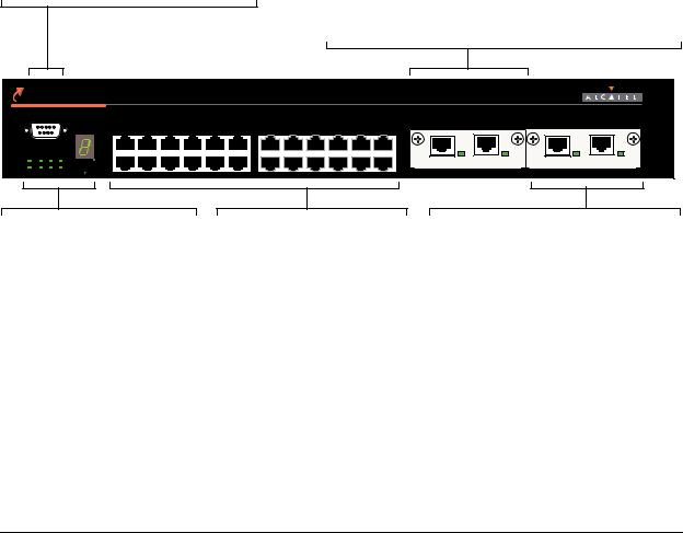
OmniSwitch 6600 Series Chassis and Hardware Components |
OmniSwitch 6624 |
|
|
|
|
OmniSwitch 6624
The OS6624 is a stackable edge/workgroup switch offering 24 10/100 Ethernet ports. The OS6624 can also be equipped with up to four Gigabit Ethernet ports for connections to a high speed backbone or server.
The front panel of the OS6624 chassis contains the following major components:
•Console (DB-9) port
•Stack indicator LED
•24 10/100 Ethernet ports
•One slot for OS6600-GNI-U2 (fiber) or OS6600-GNI-C2 (copper) Gigabit Ethernet uplink module
•One slot for Gigabit Ethernet uplink module as described above or stacking module
Refer to the illustration below for more front panel information. For detailed LED descriptions, refer to page 2-11. For information on the chassis rear panel, refer to page 2-12.
Console Port
The OS6624 front panel provides one RS232 port for console connections. Serial console connections are used by network administrators for switch management. This female DB-9 connector provides a DCE console connection.
OmniSwitch 6624
TM
Gigabit Ethernet Uplink Module Slot
The OS6624 provides a dedicated slot for Gigabit Ethernet uplink modules. This slot supports the following module types:
• OS6600-GNI-C2—Provides two fixed 1000BaseT copper connections (uses two RJ-45 connectors). Supports distances up to 100 meters.
• OS6600-GNI-U2—Provides two MiniGBIC bays that support hot-swappable 1000BASE-X MiniGBIC transceivers.
|
CONSOLE |
|
|
|
|
|
|
|
|
|
|
|
EXPANSION |
|
EXPANSION/STACKING |
|
|
|
|
|
|
|
|
|
|
|
|
|
|
|
|||
|
|
|
|
|
|
|
|
|
|
|
|
|
25 |
26 |
2 7 |
2 8 |
|
|
1 |
3 |
5 |
7 |
9 |
11 |
13 |
15 |
17 |
19 |
21 |
23 |
|
|
|
OK1 |
PS1 PRI TEMP |
|
|
|
|
|
|
|
|
|
|
|
|
LINK/ACT |
|
LINK/ACT |
|
|
|
|
|
|
|
|
|
|
|
|
|
LINK/ACT |
LINK/ACT |
||
OK2 |
PS2 SEC FAN |
SEL |
4 |
6 |
8 |
10 |
12 |
|
|
|
|
|
|
|
|
|
|
|
2 |
14 |
16 |
18 |
20 |
22 |
24 |
|
|
|
|||||
Status and Slot Indicator LEDs
For information on the OS6624’s status and slot indicator LEDs, refer to page 2-11.
Slot Selector Button
The slot selector button, located directly beneath the slot indicator LED, is used to manually assign slot numbers to switches in stacked configurations. Refer to Chapter 3, “Managing OmniSwitch 6600 Series Stacks,” for detailed information.
10/100 Ethernet Ports
The OS6624 provides 24 10/100 Ethernet ports. These ports are twisted-pair and are individually configurable as 10BaseT or 100BaseTX. The ports use RJ-45 connectors.
Stacking or Uplink Module Slot
The OS6624 provides an additional slot that can accommodate either a stacking module or a Gigabit Ethernet uplink module.
If you use a Gigabit Ethernet uplink module in this slot, the OS6624 must be used as a stand-alone switch.
A stacking module must be installed in this slot if the switch is to be used in a stack. For detailed information on stacking switches, refer to Chapter 3, “Managing OmniSwitch 6600 Series Stacks.”
OmniSwitch 6624 Front Panel
OmniSwitch 6600 Series Hardware Users Guide April 2004 |
page 2-3 |

OmniSwitch 6624 OmniSwitch 6600 Series Chassis and Hardware Components
OS6624 Specifications
Total number of 10/100 Mbps |
24 |
ports per switch |
|
|
|
Total number of Gigabit |
4 (for stand-alone switches); 2 (for stacked configurations) |
Ethernet ports per switch |
|
|
|
Total number of 10/100 Mbps |
192 (stack of eight switches) |
ports per stack |
|
|
|
Total number of Gigabit |
16 (stack of eight switches) |
Ethernet ports per stack |
|
|
|
Fabric capacity |
7.0 Gbps full duplex; 14 Gbps aggregate |
|
|
Current draw |
Approximately 2.3 Amps |
|
|
Power |
Approximately 55 Watts |
|
|
Total available power supplies |
2 (one factory-installed power supply and one optional back up power |
|
supply) |
|
|
Flash memory size |
32 MB (30 MB usable) |
|
|
RAM memory size |
128 MB |
|
|
Overall Width (rack-mount |
19.125 inches |
flanges included) |
|
|
|
Chassis Width (rack-mount |
17.2 inches |
flanges not included) |
|
|
|
Height |
2.65 inches |
|
|
Height (rack units) |
1.5 RU |
|
|
Chassis Depth |
14 inches |
|
|
Chassis Weight |
Approximately 12 lbs (13.5 lbs with optional back up power supply |
|
installed) |
|
|
Humidity |
Operating and storage relative humidity range from 10% to 95% |
|
(non-condensing) |
|
|
Altitude |
Sea level to 10,000 feet (3 km) |
|
|
|
|
10/100 Ethernet Port Specifications |
|
|
|
Connector type |
RJ-45 |
|
|
Standards supported |
IEEE 802.3u, IAB RFCs 826, 894 |
|
|
Data rate |
10 or 100 Mbps (full or half duplex) |
|
|
Maximum frame size |
1518 Bytes; 1522 Bytes with IEEE 802.1Q tags |
|
|
Connections supported |
10BaseT hub or device; 100BaseTX hub or device |
|
|
Cable supported |
10BaseT: unshielded twisted-pair (UTP) |
|
100BaseTX: unshielded twisted-pair (UTP), Category 5, EIA/TIA 568 |
|
or shielded twisted-pair (STP), Category 5, 100 ohm |
|
|
Maximum cable distance |
100 meters |
|
|
page 2-4 |
OmniSwitch 6600 Series Hardware Users Guide April 2004 |

OmniSwitch 6600 Series Chassis and Hardware Components |
OmniSwitch 6600-U24 |
|
|
|
|
OmniSwitch 6600-U24
The OS6600-U24 is a stackable edge/workgroup switch offering 24 fiber 100 Mbps Ethernet SFP ports. The OS6600-U24 can also be equipped with up to four Gigabit Ethernet ports for connections to a high speed backbone or server.
The front panel of the OS6600-U24 chassis contains the following major components:
•Console (RJ-45) port
•Stack indicator LED
•24 fiber 100 Ethernet SFP ports
•One slot for OS6600-GNI-U2 (fiber) or OS6600-GNI-C2 (copper) Gigabit Ethernet uplink module
•One slot for Gigabit Ethernet uplink module as described above or stacking module
The following SFP transceivers are available for the OS6600-U24:
•SFP-100-LC-MM—100Base FX multimode 62.5/125 and 50/125 micron fiber, supports distances up to 2 km; uses LC connectors.
•SFP-100-LC-SM15—100Base FX single mode 9/125 micron fiber, supports distances up to 15 km; uses LC connectors.
•SFP-100-LC-SM40—100Base FX single mode 9/125 micron fiber, supports distances up to 40 km; uses LC connectors.
•SFP-100-MTRJ-MM—100Base FX multimode 62.5/125 and 50/125 micron fiber, supports distances up to 2 km; uses MTRJ connectors.
Note. See “Installing SFPs (OS6600-U24)” on page 2-40 for information on installing SFP transceivers.
Refer to the illustration on the following page for more front panel information. For detailed LED descriptions, refer to page 2-11. For information on the chassis rear panel, refer to page 2-12.
OmniSwitch 6600 Series Hardware Users Guide April 2004 |
page 2-5 |
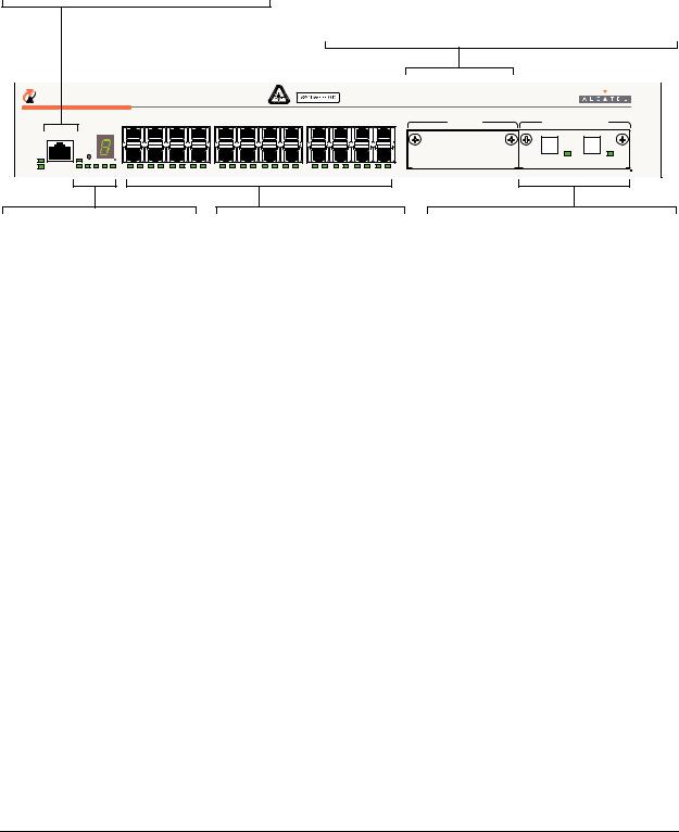
OmniSwitch 6600-U24 |
OmniSwitch 6600 Series Chassis and Hardware Components |
|
|
|
|
Console Port |
|
|
Gigabit Ethernet Uplink Module Slot |
|
|
|||
The OS6600-U24 front panel provides one RJ-45 |
The OS6600-U24 provides a dedicated slot for Gigabit Ethernet |
|||||||
port for console connections. Serial console con- |
uplink modules. This slot supports the following module types: |
|||||||
nections are used by network administrators for |
• OS6600-GNI-C2—Provides two fixed 1000BaseT copper |
|||||||
switch management. This female RJ-45connector |
connections (uses two RJ-45 connectors). Supports distances |
|||||||
provides a DCE console connection. |
|
up to 100 meters. |
|
|
|
|
||
|
|
|
|
• OS6600-GNI-U2—Provides two MiniGBIC bays that |
||||
|
|
|
|
support hot-swappable 1000BASE-X MiniGBIC transceivers. |
||||
TM OmniSwitch 6600-U24 |
|
|
|
|
|
|
||
|
|
1 3 5 7 |
9 11 13 15 |
17 19 21 23 |
|
EXPANSION |
EXPANSION/STACKING |
|
|
|
|
|
|
25 |
26 |
2 7 |
2 8 |
|
CONSOLE |
|
|
|
|
|
|
|
|
|
SEL |
|
|
|
|
|
|
OK1 |
PS1 |
2 |
|
24 |
|
|
|
|
|
|
|
|
|
|
|
LINK/ACT |
LINK/ACT |
OK2 |
PS2 PRI SEC FAN TEMP |
1 |
2 |
3 |
4 |
5 |
6 |
7 |
8 |
9 |
10 |
11 |
12 |
13 |
14 |
15 |
16 |
17 |
18 |
19 |
20 |
21 |
22 |
23 |
24 |
Status and Slot Indicator LEDs
For information on the OS6600U24’s status and slot indicator LEDs, refer to page 2-11.
Slot Selector Button
The slot selector button, located directly beneath the slot indicator LED, is used to manually assign slot numbers to switches in stacked configurations. Refer to Chapter 3, “Managing OmniSwitch 6600 Series Stacks,” for detailed information.
100 Fiber Ethernet SFP Ports
The OS6600-U24 provides 24 fiber 100 Ethernet SFP ports. These ports can use the SFP-100- LC-MM, SFP-100-LC-SM, and SFP-100-MTRJ-MM transceivers in any combination.
Stacking or Uplink Module Slot
The OS6600-U24 provides an additional slot that can accommodate either a stacking module or a Gigabit Ethernet uplink module.
If you use a Gigabit Ethernet uplink module in this slot, the OS6600-U24 must be used as a stand-alone switch.
A stacking module must be installed in this slot if the switch is to be used in a stack. For detailed information on stacking switches, refer to Chapter 3, “Managing OmniSwitch 6600 Series Stacks.”
OmniSwitch 6600-U24 Front Panel
page 2-6 |
OmniSwitch 6600 Series Hardware Users Guide April 2004 |

OmniSwitch 6600 Series Chassis and Hardware Components OmniSwitch 6600-U24
OS6600-U24 Specifications
Total number of 100 Mbps SFP |
24 |
ports per switch |
|
|
|
Total number of Gigabit |
4 (for stand-alone switches); 2 (for stacked configurations) |
Ethernet ports per switch |
|
|
|
Total number of 100 Mbps SFP |
192 (stack of eight switches) |
ports per stack |
|
|
|
Total number of Gigabit |
16 (stack of eight switches) |
Ethernet ports per stack |
|
|
|
Fabric capacity |
7.0 Gbps full duplex; 14 Gbps aggregate |
|
|
Power |
The OS6600-U24 power supply provides 100 W |
|
|
Total available power supplies |
2 (one factory-installed power supply and one optional back up power |
|
supply) |
|
|
Flash memory size |
32 MB (30 MB usable) |
|
|
RAM memory size |
128 MB |
|
|
Overall Width (rack-mount |
19.125 inches |
flanges included) |
|
|
|
Chassis Width (rack-mount |
17.2 inches |
flanges not included) |
|
|
|
Height |
2.65 inches |
|
|
Height (rack units) |
1.5 RU |
|
|
Chassis Depth |
14 inches |
|
|
Chassis Weight |
Approximately 11.56 lbs not including uplink/stacking modules or |
|
SFPs (13.06 lbs with optional back up power supply installed) |
|
|
Humidity |
Operating and storage relative humidity range from 10% to 95% |
|
(non-condensing) |
|
|
Altitude |
Sea level to 10,000 feet (3 km) |
|
|
OmniSwitch 6600 Series Hardware Users Guide April 2004 |
page 2-7 |

OmniSwitch 6600-U24 OmniSwitch 6600 Series Chassis and Hardware Components
100 Mbps Ethernet SFP Port Specifications
Connector type |
SFP |
|
|
Standards supported |
IEEE 802.3u, IAB RFCs 826, 894 (see data sheet for more information) |
|
|
Data rate |
100 Mbps (full or half duplex) |
|
|
Maximum frame size |
1518 Bytes; 1522 Bytes with IEEE 802.1Q tags |
|
|
Connections supported |
100BaseFX |
|
|
Cable supported |
SFP-100-LC-MM: 62.5/125 and 50/125 micron multimode fiber |
|
SFP-100-LC-SM: 9/125 micron single mode |
|
SFP-100-MTRJ-MM: 62.5/125 and 50/125 micron multimode fiber |
|
|
Optical output power |
SFP-100-LC-MM: -19 to -14 dBm (62.5/125 micron); |
|
-22.5 to -14 dBm (50/125 micron) |
|
SFP-100-LC-SM15: -15 to -8 dBm |
|
SFP-100-LC-SM40: -5 to 0 dBm |
|
SFP-100-MTRJ-MM: -20 to -14 dBm |
|
|
Input optical power |
SFP-100-LC-MM: -31 to -14 dBm |
(Receiver sensitivity) |
SFP-100-LC-SM15: -31 to 0dBm |
|
SFP-100-LC-SM40: -34 to 0 dBm |
|
SFP-100-MTRJ-MM: -31 to -14 dBm |
|
|
Maximum cable distance |
SFP-100-LC-MM: 2 km |
|
SFP-100-LC-SM15: 15 km |
|
SFP-100-LC-SM40: 40 km |
|
SFP-100-MTRJ-MM: 2 km |
|
|
page 2-8 |
OmniSwitch 6600 Series Hardware Users Guide April 2004 |
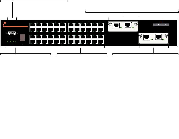
OmniSwitch 6600 Series Chassis and Hardware Components |
OmniSwitch 6648 |
|
|
|
|
OmniSwitch 6648
The OS6648 is a stackable edge/workgroup switch offering 48 10/100 Ethernet ports. The OS6648 can also be equipped with up to four Gigabit Ethernet ports for connections to a high speed backbone or server.
The front panel of the OS6648 chassis contains the following major components:
•Console (DB-9) port
•Stack indicator LED
•48 10/100 Ethernet ports
•One slot for OS6600-GNI-U2 (fiber) or OS6600-GNI-C2 (copper) Gigabit Ethernet uplink module
•One slot for Gigabit Ethernet uplink module as described above or stacking module
Refer to the illustration below for more front panel information. For detailed LED descriptions, refer to page 2-11. For information on the chassis rear panel, refer to page 2-12.
Console Port
The OS6648 front panel provides one RS232 port for console connections. Serial console connections are used by network administrators for switch management. This female DB-9 connector provides a DCE console connection.
Gigabit Ethernet Uplink Module Slot
The OS6648 provides a dedicated slot for Gigabit Ethernet uplink modules. This slot supports the following module types:
• OS6600-GNI-C2—Provides two fixed 1000BaseT copper connections (uses two RJ-45 connectors). Supports distances up to 100 meters.
• OS6600-GNI-U2—Provides two MiniGBIC bays that support hot-swappable 1000BASE-X MiniGBIC transceivers.
|
|
25 |
27 |
29 |
31 |
33 |
35 |
37 |
39 |
41 |
43 |
45 |
47 |
|
|
|
|
TM OmniSwitch 6648 |
|
|
|
|
|
|
|
|
|
|
|
|
|
|
|
||
|
|
|
|
|
|
|
|
|
|
|
|
|
|
LINK/ACT |
LINK/ACT |
|
|
|
CONSOLE |
|
|
|
|
|
|
|
|
|
|
|
|
|
|
EXPANSION/STACKING |
|
|
|
|
|
|
|
|
|
|
|
|
|
|
|
|
|
||
|
|
26 |
28 |
30 |
32 |
34 |
36 |
38 |
40 |
42 |
44 |
46 |
48 |
49 |
50 |
5 1 |
5 2 |
|
|
EXPANSION |
|
|
|
||||||||||||
|
|
1 |
3 |
5 |
7 |
9 |
11 |
13 |
15 |
17 |
19 |
21 |
23 |
|
|
|
|
OK1 |
PS1 PRI TEMP |
|
|
|
|
|
|
|
|
|
|
|
|
|
|
|
LINK/ACT |
|
|
|
|
|
|
|
|
|
|
|
|
|
|
|
|
LINK/ACT |
|
OK2 |
PS2 SEC FAN |
SEL |
|
|
|
|
|
|
|
|
|
|
|
|
|
|
|
|
|
2 |
4 |
6 |
8 |
10 |
12 |
14 |
16 |
18 |
20 |
22 |
24 |
|
|
|
|
Status and Slot Indicator LEDs
For information on the OS6648’s status and slot indicator LEDs, refer to page 2-11.
Slot Selector Button
The slot selector button, located directly beneath the slot indicator LED, is used to manually assign slot numbers to switches in stacked configurations. Refer to Chapter 3, “Managing OmniSwitch 6600 Series Stacks,” for detailed information.
10/100 Ethernet Ports
The OS6648 provides 48 10/100 Ethernet ports. These ports are twisted-pair and are individually configurable as 10BaseT or 100BaseTX. The ports use RJ-45 connectors.
Stacking or Uplink Module Slot
The OS6648 provides an additional slot that can accommodate either a stacking module or a Gigabit Ethernet uplink module.
If you use a Gigabit Ethernet uplink module in this slot, the OS6648 must be used as a stand-alone switch.
A stacking module must be installed in this slot if the switch is to be used in a stack. For detailed information on stacking switches, refer to Chapter 3, “Managing OmniSwitch 6600 Series Stacks.”
OmniSwitch 6648 Front Panel
OmniSwitch 6600 Series Hardware Users Guide April 2004 |
page 2-9 |

OmniSwitch 6648 OmniSwitch 6600 Series Chassis and Hardware Components
OS6648 Specifications
Total number of 10/100 Mbps |
48 |
ports per switch |
|
|
|
Total number of Gigabit Ether- |
4 (for standalone switches); |
net ports per switch |
2 (for stacked configurations) |
|
|
Total number of 10/100 Mbps |
384 (stack of eight switches) |
ports per stack |
|
|
|
Total number of Gigabit Ether- |
16 (stack of eight switches) |
net ports per stack |
|
|
|
Fabric capacity |
10.0 Gbps full duplex; 20.0 Gbps aggregate |
|
|
Current draw |
Approximately 2.3 Amps |
|
|
Power |
Approximately 55 Watts |
|
|
Total power supplies |
2 (one factory-installed power supply and |
|
one optional back up power supply) |
|
|
Flash memory size |
32 MB (30 MB usable) |
|
|
RAM memory size |
128 MB |
|
|
Overall Width (rack-mount |
19.125 inches |
flanges included) |
|
|
|
Chassis Width (rack-mount |
17.2 inches |
flanges not included) |
|
|
|
Height |
2.65 inches |
|
|
Height (rack units) |
1.5 RU |
|
|
Chassis Depth |
14 inches |
|
|
Chassis Weight |
Approximately 14 lbs (15.5 lbs with optional |
|
back up power supply installed) |
|
|
Humidity |
Operating and storage relative humidity range from 10% to 95% |
|
(non-condensing) |
|
|
Altitude |
Sea level to 10,000 feet (3 km) |
|
|
|
|
10/100 Ethernet Port Specifications |
|
|
|
Connector type |
RJ-45 |
|
|
Standards supported |
IEEE 802.3u, IAB RFCs 826, 894 |
|
|
Data rate |
10 or 100 Mbps (full or half duplex) |
|
|
Maximum frame size |
1518 Bytes; 1522 Bytes with IEEE 802.1Q tags |
|
|
Connections supported |
10BaseT hub or device; 100BaseTX hub or device |
|
|
Cable supported |
10BaseT: unshielded twisted-pair (UTP) |
|
100BaseTX: unshielded twisted-pair (UTP), Category 5, EIA/TIA 568 |
|
or shielded twisted-pair (STP), Category 5, 100 ohm |
|
|
Maximum cable distance |
100 meters |
|
|
page 2-10 |
OmniSwitch 6600 Series Hardware Users Guide April 2004 |
Loading...