


 Loading...
OmniAccess 740
Hardware Users Guide
Release 2.2
26801 West Agoura Road
Calabasas, CA 91301 (818) 880-3500 FAX (818) 880-3505
support@ind.alcatel.com US Customer Support—(800) 995-2696 International Customer Support—(818) 878-4507 Internet—service.esd.alcatel-lucent.com Website: www.alcatel-lucent.com
Part No: 032288-00, Rev. A
Copyright
The Specifications and Information regarding the products in this manual are subject to change without notice. All statements, information, and recommendations in this manual are believed to be accurate but are presented without warranty of any kind, express or implied. Users must take full responsibility for their application of any products.
THE SOFTWARE LICENSE AND LIMITED WARRANTY FOR THE ACCOMPANYING PRODUCT ARE SET FORTH IN THE INFORMATION PACKET THAT SHIPPED WITH THE PRODUCT AND ARE INCORPORATED HEREIN BY THIS REFERENCE.
This equipment has been tested and found to comply within the limits pursuant to the (Centre for Telecom) rules. These limits are designed to provide protection against harmful interference when the equipment is operated in a commercial environment.
The following information is for the Users of the OmniAccess 740: If it is not installed in accordance with the installation instructions, it may not function exactly to the said specifications. Modifying the equipment without Alcatel-Lucent's written authorization may result in the equipment no longer complying with the said dimensions.
Copyright © 2007, Alcatel-Lucent. All rights reserved.
Not withstanding any other warranty herein, all hardware and software are provided "as is" with all faults. Alcatel-Lucent disclaim all warranties, expressed or implied, including, without limitation, those of merchantability, fitness for a particular purpose and non-infringement or arising from a course of dealing, usage, or trade practice. In no event shall Alcatel-Lucent be liable for any indirect, special, consequential, or incidental damages, including, without limitation, lost profits or loss or damage to data arising out of the use or inability to use this manual, even if Alcatel-Lucent have been advised of the possibility of such damages.
Table of Contents |
|
|
1 |
Preface............................................................................................................ |
1 |
|
About this Guide........................................................................................................................ |
1 |
|
Chapter Description .................................................................................................................. |
1 |
|
Audience ................................................................................................................................... |
1 |
|
Document Organization ............................................................................................................ |
2 |
|
Document Conventions............................................................................................................. |
2 |
|
Obtaining Documentation.......................................................................................................... |
3 |
|
Reference Publications ............................................................................................................. |
3 |
|
Obtaining Technical Assistance ................................................................................................ |
3 |
|
Documentation Feedback ......................................................................................................... |
3 |
2 |
OmniAccess 740 Overview........................................................................... |
5 |
|
Introduction ............................................................................................................................... |
5 |
|
OA-740 Overview...................................................................................................................... |
6 |
|
Package Contents..................................................................................................................... |
6 |
|
Hardware Overview................................................................................................................... |
7 |
|
The OA-740 ........................................................................................................................ |
7 |
|
User Modules ................................................................................................................... |
13 |
|
System Specifications ............................................................................................................. |
24 |
|
Valid System Configuration .............................................................................................. |
24 |
3 Installing the OmniAccess 740................................................................... |
25 |
|
|
Preparing for Installation ......................................................................................................... |
26 |
|
Required Tools and Equipment ........................................................................................ |
26 |
|
Installation Checklist ............................................................................................................... |
26 |
|
Safety Measures ..................................................................................................................... |
27 |
|
Preventing Injury............................................................................................................... |
27 |
|
Equipment Guidelines ...................................................................................................... |
28 |
|
Lifting Safely ..................................................................................................................... |
29 |
|
Safety with Electricity........................................................................................................ |
29 |
|
Preventing Electrostatic Discharge Damage .................................................................... |
30 |
|
Site Requirement Guidelines .................................................................................................. |
31 |
|
Power Supply Overview .......................................................................................................... |
32 |
|
Power Supply Specifications ............................................................................................ |
32 |
|
Plant Wiring ...................................................................................................................... |
34 |
|
General Installation ................................................................................................................. |
35 |
|
Rack-Mounting the OA-740..................................................................................................... |
36 |
|
Parts Required.................................................................................................................. |
37 |
|
Installing the OA-740 in the Rack ..................................................................................... |
38 |
|
Installing User Modules........................................................................................................... |
39 |
|
Installing Line Cards ......................................................................................................... |
39 |
|
Installing Fillers................................................................................................................. |
40 |
4 Starting the OmniAccess 740...................................................................... |
41 |
Introduction ............................................................................................................................. |
41 |
Checking Conditions Prior to System Startup ......................................................................... |
42 |
Starting the OA-740 ................................................................................................................ |
42 |
Connecting to the System Console Port ................................................................................. |
44 |
Performing Basic Configuration Tasks.................................................................................... |
46 |
Accessing OA-740 Through CLI....................................................................................... |
46 |
Connecting the System to the Network................................................................................... |
51 |
Connecting to Internal Network ........................................................................................ |
51 |
Connecting Through External Network............................................................................. |
54 |
Site Log................................................................................................................................... |
55 |
Appendix A Regulatory Compliance and Safety Information.......................... |
1 |
Declaration of Conformity: CE Mark.......................................................................................... |
1 |
Waste Electrical and Electronic Equipment (WEEE) Statement ........................................ |
2 |
China RoHS: Hazardous Substance Table............................................................................... |
3 |
Standards Compliance.............................................................................................................. |
5 |
Safety ................................................................................................................................. |
5 |
EMC.................................................................................................................................... |
5 |
Telecom.............................................................................................................................. |
5 |
Declaration of Conformity Addendum................................................................................. |
6 |
FCC Class A, Part 15 ......................................................................................................... |
7 |
Canada Class A Statement ................................................................................................ |
8 |
JATE................................................................................................................................... |
8 |
CISPR22 Class A warning.................................................................................................. |
8 |
VCCI ................................................................................................................................... |
8 |
Class A Warning for Taiwan and Other Chinese Markets .................................................. |
9 |
Translated Safety Warnings.................................................................................................... |
10 |
Instrucciones de seguridad en español................................................................................... |
16 |
Appendix B AC Power Specifications.............................................................. |
19 |
Appendix C Pin Connector Details for OmniAccess 740............................... |
21 |
RJ-11 Modem Connector Pin Assignments...................................................................... |
21 |
RJ-45 Console Connector Pin Assignments .................................................................... |
22 |
T1E1 Connector Pin Assignments.................................................................................... |
23 |
SE/L2GE Connector Pin Assignments ............................................................................. |
24 |
Serial Card (V.35/X.21) Connector Pin Assignments ....................................................... |
25 |
List of Figures
The OA-740 Chassis 8
Air Flow Through the OA-740 9 Front Panel 10
Rear Panel 10
OA-740 (4-Slot Chassis) 11 Services Engine 13
4-port T1E1 Line Card 15 GigE Line Card 17
Serial Line Card (V.35/X.21) 20 Ports on the Front Panel 23 Connecting Power Cord 33 Rack Mounting the OA-740 38 Installing Services Engine 39 Installing Line Card 40
Connecting to the System Console 44 Connecting to Internal Network 52 Connecting through External Network 54 RJ-11 Connector 21
RJ-45 Connector 22
Serial Card (V.35/X.21) Connector 25
List of Tables
OA-740 Chassis Physical Specifications 9 Slot Numbers 11
LED Status 11
Cable Connections 12 SE Card LEDs 14
LEDs for Ethernet Port on SE Card 14 T1E1 Card LEDs 16
T1E1 Port LEDs 16
T1E1 Mode LEDs 17
GigE Card LEDs 18
LEDs for each Port on GigE Card 18 Serial Card (V.35/X.21) LEDs 21 Serial (V.35/X.21) Port LEDs 21
Serial Card (V.35/X.21) Cable Part Numbers 22 Environmental Specifications 24
Power Specifications 24
Physical Specifications 24 Environmental Site Requirements 31 LED Status 42
Console Properties 45
AC Power Supply Specifications 19
Pin Connector Details for RJ-11 Connector 21 Pin Connector Details for RJ-45 Connector 22 T1E1 Card Port Connector Pin Assignment 23
10/100/1000 Mbps Port Connector Pin Assignment on SE/L2GE Card 24 Pin Connector Details for Serial Line Card 25
Serial Card V.35 DTE Cable Pin-out 28

CHAPTER 1
PREFACE
ABOUT THIS GUIDE
This hardware users guide explains the initial hardware installation and the configuration procedures for the OmniAccess 740 (OA-740). It contains procedures for unpacking and installing the OA-740 system hardware, starting up the system, and creating a basic configuration. After completing the installation and basic configuration procedures covered in this guide, use the appropriate companion publications to more completely configure your system.
CHAPTER DESCRIPTION
This chapter explains the objectives, intended audience, organization of the OA-740 Hardware Users Guide, and defines the conventions used to convey instructions and information.
AUDIENCE
This book is intended for networking professionals who are responsible for designing, implementing, and managing enterprise networks. This book aims to provide unique technology and effective practices that deliver value on the networking perspective.
The user is expected to have, at minimum, an introductory understanding of the following:
•Networking applications
•Telecommunication networks
•Hardware configuration
Alcatel-Lucent
OmniAccess 740 Hardware User’s Guide |
1 |

OmniAccess 740 Hardware User’s Guide
DOCUMENT ORGANIZATION
This hardware users guide is organized into following chapters and appendix:
Chapter 2 OmniAccess 740 Overview describes the functional description of OA-740 and provides functional overview of the system.
Chapter 3 Installing the OmniAccess 740 is a preparatory chapter that describes safety considerations, tools required, an overview of the installation, and hardware installation procedures.
Chapter 4 Starting the OmniAccess 740 provides procedure for starting the OA740, performing basic configuration tasks, and connecting the system to internal and external networks.
Appendix provides additional information on the regulatory compliances and safety, AC power supply, and Pin Connector details for the OA-740.
DOCUMENT CONVENTIONS
The following conventions are used to attract the attention of the reader:
Note: Means reader take note. Notes contain helpful suggestions/information/references to materials. Take a note of instructions provided here.
Caution: Means reader be careful. Failure to observe the cautionary note could result in equipment damage or loss of data.
Safety Warnings:
Warning: FOLLOW THE IMPORTANT SAFETY INSTRUCTIONS.
Means reader be extremely cautious. Failure to observe the warning note could result in injury to the user, equipment damage, and/or loss of data.
This warning means danger. You are in a situation that could cause bodily injury. Before you work on any equipment, be aware of the hazards involved with electrical circuitry and be familiar with standard practices for preventing accidents.
Alcatel-Lucent
2 |
OmniAccess 740 Hardware User’s Guide |
Obtaining Documentation
OBTAINING DOCUMENTATION
Alcatel-Lucent provides several ways to obtain technical assistance and other technical resources. Documents can be downloaded from our support site service.esd.alcatel-lucent.com.
REFERENCE PUBLICATIONS
The following publications are a part of the Alcatel-Lucent documentation suite:
•OmniAccess 700 CLI Command Reference Guide (Release 2.2)
•OmniAccess 700 CLI Configuration Guide (Release 2.2)
•OmniAccess 700 Web GUI Users Guide (Release 2.2)
•OmniAccess 700 Getting Started Guide (Release 2.2)
•OmniAccess 780 Hardware Users Guide (Release 2.2)
OBTAINING TECHNICAL ASSISTANCE
For all customers, partners, resellers, and distributors who hold valid Alcatel-Lucent service contracts, the Alcatel-Lucent Technical Support Team provides 24-hour-a-day, technical support services online and over the phone.
For Customer issues and help, contact: Alcatel-Lucent
US Customer Support: (800) 995-2696 International Customer Support: (818) 878-4507
E-mail: support@ind.alcatel.com Website: service.esd.alcatel-lucent.com
DOCUMENTATION FEEDBACK
We value your comments and suggestions about our documentation. If you have any comments about this book, please enter them through the feedback link on the Alcatel-Lucent Website. We will use your feedback in our plans to improve the documentation.
Alcatel-Lucent
OmniAccess 740 Hardware User’s Guide |
3 |

OmniAccess 740 Hardware User’s Guide
Alcatel-Lucent
4 |
OmniAccess 740 Hardware User’s Guide |

CHAPTER 2
OmniAccess 740 OVERVIEW
INTRODUCTION
This chapter provides physical and functional overview of the OmniAccess 740 (OA-740). It contains the functional description of OA-740 hardware, its major components, and related features. Descriptions and examples of software commands are included only when they are necessary for replacing, installing, configuring, or maintaining the OA-740 hardware.
This chapter contains the following sections:
•OA-740 Overview
•Package Contents
•Hardware Overview
•System Specifications
Alcatel-Lucent
OmniAccess 740 Hardware User’s Guide |
5 |

OmniAccess 740 Overview
OA-740 OVERVIEW
The OA-740 is designed to provide most commonly used network services, such as routing, switching, wide area network (WAN) connectivity, network security with firewall, and related services.
PACKAGE CONTENTS
1.The OA-740
•4-slot Chassis that includes
•Services Engine (SE) - 2-port 10/100/1000 Mbps Ethernet
•3 Fans (built-in)
•Power Supply (built-in)
2.Optional Modules
•4-port T1E1 Line Card
•8-port 10/100/1000 Mbps Gigabit Ethernet (GigE) Line Card
•4-port Serial Line Card (V3.5/X.21)
3.Miscellaneous
•AC Power Cord
•Console Cable
•Rack Mount Screws
•19-inch Rack Mount Ears
•512 MB USB Memory Flash
•Product Documentation CD ROM
Alcatel-Lucent
6 |
OmniAccess 740 Hardware User’s Guide |

Hardware Overview
HARDWARE OVERVIEW
The following section provides a detailed overview of the hardware components of OA-740.
THE OA-740
OA-740 has 4 line card slots, numbered 0 to 3 from left to right. The slots 2 and 3 can be combined to support a dual slot line card (such as the SE). All the OA-740 cards support Online Insertion and Removal (OIR) feature.
The OA-740 has the following components:
•OA-740 Chassis
•SE
Alcatel-Lucent
OmniAccess 740 Hardware User’s Guide |
7 |
OmniAccess 740 Overview
OA-740 CHASSIS
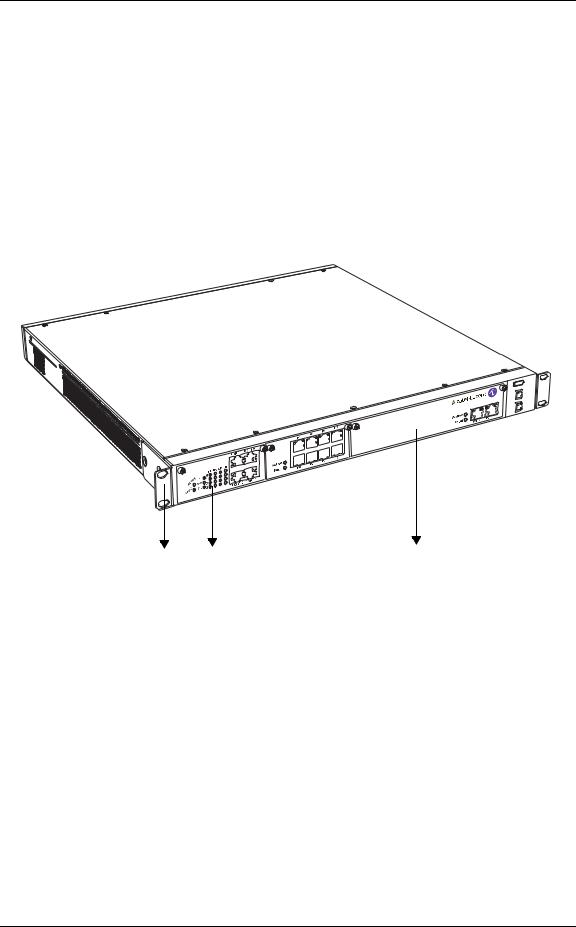
OA-740 chassis is a rigid sheet metal structure that houses the other hardware components. one rack-unit (1 RU) chassis has a front panel, a rear panel, and perforated side panels for air flow. The chassis also integrates a power supply unit and a cooling unit.
The chassis is of 1.73-inch (4.4 cm) height, 17.5-inch (44.5 cm) width, and 17-inch (43.2 cm) depth. It weighs approximately 26.4 lbs (12.8 kgs).
Figure 1 shows an OA-740 chassis.
Console Modem USB |
OmniAccess 740 |
OA7 |
-SE |
|
OA7 |
-6E |
-8 |
|
||
|
|
OA7 |
-T1E1 |
-4 |
|
||
|
|
3 |
2 |
1 |
|
1.SE
2.4-port T1E1 Line Card
3.Rack Mount Flange
Figure 1: The OA-740 Chassis
Alcatel-Lucent
8 |
OmniAccess 740 Hardware User’s Guide |
Hardware Overview
Table 1 summarizes the physical specifications of the OA-740 chassis.
Table 1: OA-740 Chassis Physical Specifications
Parameter |
Value |
|
|
Chassis height |
1.73-inch (4.4 cm) |
|
|
Chassis width |
17.5-inch (44.5 cm) |
|
19-inch (48.3 cm) with rack mount |
|
brackets |
|
|
Chassis depth |
17-inch (43.2 cm) |
|
|
Chassis weight |
26.4 lbs (12.8 kgs) maximum |
|
configuration |
|
|
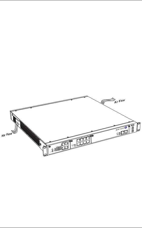
Figure 2 shows the air flow pattern through OA-740 chassis.
Console |
OmniAccess 740 |
USB |
|
Modem |
|
OA7 |
-SE |
|
OA7 |
-6E |
-8 |
|
||
|
|
OA7 |
-T1E1 |
-4 |
|
||
|
|
Figure 2: Air Flow Through the OA-740
The chassis has a built-in power supply system which provides power for all the OA-740 components. (Refer to the “AC Power Specifications” chapter for power supply specifications.) The chassis also has built-in fans for efficient cooling of the OA-740, which prevents damages due to overheating of the OA-740 components.
Alcatel-Lucent
OmniAccess 740 Hardware User’s Guide |
9 |
OmniAccess 740 Overview
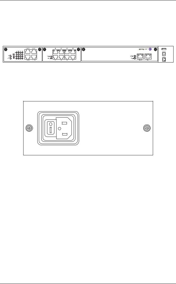
The front panel houses SE, line cards, status LEDs, communication ports, and card ejectors. The communication ports on the front panel provide LAN/WAN and console connectivity to the system. All the cards in the front panel dock into respective slots in the back plane. The front panel also houses rack-mount flanges that help the system to be loaded on to a 19-inch rack.
OA7-T1E1-4 |
OA7-SE |
OA7-6E-8
Console Modem USB
OmniAccess 740
Figure 3: Front Panel
The rear panel provides power supply connectivity to the OA-740.
Figure 4: Rear Panel
Alcatel-Lucent
10 |
OmniAccess 740 Hardware User’s Guide |
Hardware Overview
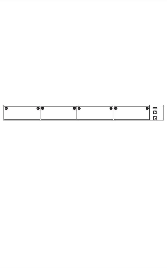
SLOT NUMBERS
The slots in the front panel are numbered 0 through 3, from left to right. The table below lists the slot number and the component associated with it.
Table 2: Slot Numbers
Slot Number |
Location |
Slot Type |
Card Associated With the Slot |
|
Number |
||||
|
|
|
||
|
|
|
|
|
0 |
Front Panel |
Single |
Line Card |
|
|
|
|
|
|
1 |
Front Panel |
Single |
Line Card |
|
|
|
|
|
|
2 |
Front Panel |
Dual |
SE |
|
|
|
|
|
|
3 |
Front Panel |
Dual |
SE |
|
|
|
|
|
0 |
1 |
2 |
3 |
Console Modem USB
OmniAccess 740
Figure 5: OA-740 (4-Slot Chassis)
LED INFORMATION
The following table shows the state of the main LEDs after startup.
Table 3: LED Status
LED |
Status |
Description |
|
|
|
SE LEDs |
|
|
|
|
|
Active |
Off |
Power up status. This is the default |
|
|
display when the system is first |
|
|
powered on and before the software is |
|
|
loaded. |
|
|
|
|
Green |
SE card is active. |
|
|
|
|
Yellow |
Indicates transient conditions (e.g., |
|
|
booting). |
|
|
|
Alcatel-Lucent
OmniAccess 740 Hardware User’s Guide |
11 |

OmniAccess 740 Overview
CABLE CONNECTION TABLE
The following table summarizes the cable connections for the OA-740.
Table 4: Cable Connections
Port or Module |
Port Type |
Connect To |
|
|
|
Power Unit |
IEC 60320 (320) C-14 Power Inlet |
Main power supply. |
|
|
|
Ethernet |
RJ-45 |
Ethernet hub or switch. |
|
|
|
T1E1 |
RJ-45 |
T1E1 network. |
|
|
|
Console |
RJ-45 |
PC or VT100 |
|
|
|
Modem |
RJ-11 |
Telephone Line |
|
|
|
Serial |
68 pin VHDCI Connector |
V.35/X.21 modem |
|
|
|
BACK PLANE
The back panel in the OA-740 provides docking slots for the SE card, the line cards, and performs switching functions.
Alcatel-Lucent
12 |
OmniAccess 740 Hardware User’s Guide |
Hardware Overview
USER MODULES
This section provides description about the modules/components that can be installed by the user.
LINE CARDS
All the line cards can be mounted on a single slot except the SE card, which requires two slots. Next generation SE line cards may occupy a single slot only. An overview of the line cards is given below.
SERVICES ENGINE
The SE card is the main data processing center in the chassis. The SE card has two external auto-negotiable copper GigE ports. The GigE interfaces can autonegotiate, transmit, and receive data packets at the rate of 10/100/1000 Mbps.
The LEDs on the SE card indicate Active or Fault conditions. The LEDs on the Gigabit Ethernet ports of the SE card indicate Link Status, Link Speed, and Activity. The SE card is a dual slot line card, and is installed in slots 2, 3.
4 5
OA7-SE
1 |
2 |
|
3 |
||
|
1.SE LEDs
2.GigE Ports
3.Thumb Screw
4.Left LED on the Ethernet Port
5.Right LED on the Ethernet Port
Figure 6: Services Engine
Alcatel-Lucent
OmniAccess 740 Hardware User’s Guide |
13 |

OmniAccess 740 Overview
SE Card LEDs
SE card has status LEDs for the card and for each of its Ethernet ports.
Table 5: SE Card LEDs
LED |
Status |
Description |
|
|
|
Active |
Green |
SE card is active. |
|
|
|
Fault |
Red |
Reload in progress. |
|
|
|
Table 6: LEDs for Ethernet Port on SE Card |
||
|
|
|
LED |
Status |
Description |
|
|
|
Left LED |
Green |
Link Speed is 1000/10 Mbps. |
|
|
|
|
Yellow |
Link Speed is 100 Mbps. |
|
|
|
|
Off |
Link is not active |
|
|
|
Right LED |
Amber |
Traffic is active. |
|
|
|
|
Off |
Traffic is not active. |
|
|
|
Alcatel-Lucent
14 |
OmniAccess 740 Hardware User’s Guide |

Hardware Overview
4-PORT T1E1 LINE CARD
The 4-port T1E1 line card supports American and European (International) digital transmission standards. The card is a single slot line card, and is installed either in slot 0 or 1. The 4-port T1E1 line card has 4 RJ-45 interfaces. Each interface can support data rates of 1.544 or 2 Mbps depending on the type of connectivity.
The figure below shows the 4-port T1E1 Line Card.
OA7-T1E1-4
|
|
|
|
|
|
|
3 |
|
|
|
|
|
|
|
|
|
|
|
|
|
|
|
|
|
|
|
|
|
|
|
|
|
|
|
|
|
|
|
2 |
|
|
|
4 |
|
|
||
1 |
|
|
|
|
5 |
||||||
|
|
|
|||||||||
1.T1E1 Card LEDs
2.T1E1 Mode LEDs
3.T1E1 Port LEDs
4.RJ-45 Interfaces
5.Thumb Screw
Figure 7: 4-port T1E1 Line Card
Alcatel-Lucent
OmniAccess 740 Hardware User’s Guide |
15 |

OmniAccess 740 Overview
4-port T1E1 Line Card LEDs
The LEDs on the 4-port T1E1 line card indicate Active or Fault condition; T1 mode, E1 Balanced (E1B) mode, and E1 Unbalanced (E1U) mode. The 4x4 LEDs on the front of the card indicate Local Alarm, Remote Alarm, Carrier Detect, and Loopback for the 4 ports.
The following tables describe the status of LEDs on the 4-port T1E1 line card.
Table 7: T1E1 Card LEDs
LED |
Status |
Description |
|
|
|
Active |
Green |
4-port T1E1 line card is active. |
|
|
|
|
Yellow |
Indicates transient conditions (e.g., |
|
|
booting). |
|
|
|
Fault |
Red |
Reload in progress. |
|
|
|
Table 8: T1E1 Port LEDs |
|
|
|
|
|
LED |
Status |
Description |
|
|
|
Local Alarm (LA) |
On |
Indicates either Red or Yellow alarm |
|
|
present or Transmitting Blue/AIS alarm. |
|
|
|
|
Off |
Indicates neither Red nor Yellow alarm |
|
|
is present and transmitter also not |
|
|
transmitting AIS/Blue Alarm. |
|
|
|
Remote Alarm (RA) |
On |
Remote System is transmitting Blue/ |
|
|
AIS alarm. |
|
|
|
|
Off |
Remote system is not transmitting any |
|
|
alarm. |
|
|
|
Carrier Detect (CD) |
On |
Carrier detected (cable plugged in). |
|
|
|
|
Off |
Carrier not detected (cable plugged |
|
|
out). |
|
|
|
Loopback (LB) |
On |
Indicates port is in any of the local or |
|
|
network Loopback mode. |
|
|
|
|
Off |
Port is not in Loopback mode. |
|
|
|
Note: You will see LED activity only when the port is administratively up.
Alcatel-Lucent
16 |
OmniAccess 740 Hardware User’s Guide |
|
|
|
|
|
|
|
Hardware Overview |
|
|
|
|
|
|
||
|
Table 9: T1E1 Mode LEDs |
|
|
||||
|
|
|
|
|
|
|
|
|
|
T1 |
|
E1B |
|
E1U |
Description |
|
|
|
|
|
|
|
|
|
On |
|
Off |
|
Off |
|
Line card configured in the T1 mode. |
|
|
|
|
|
|
|
|
|
Off |
|
On |
|
Off |
|
Line card Configured in the E1 balanced |
|
|
|
|
|
|
|
mode. |
|
|
|
|
|
|
|
|
|
Off |
|
Off |
|
On |
|
Line card configured in the E1 unbalanced |
|
|
|
|
|
|
|
mode. |
|
|
|
|
|
|
|
|
|
Off |
|
Off |
|
Off |
|
No mode configured on the line card. |
|
|
|
|
|
|
|
|
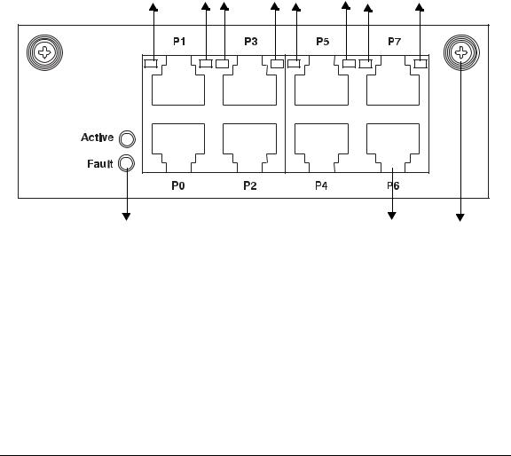
L2 8-PORT GIGABIT ETHERNET LINE CARD
The 8-port GigE line card provides Layer-2 switching functions. The card is a single slot line card, and is installed either in slot 0 or 1. The GigE card has 8 RJ45 interfaces. These interfaces can auto-negotiate, transmit, and receive data packets at the rate of 10/100/1000 Mbps.
GigE Port LED 0 LED1 LED2 LED3 LED4 LED5 LED6 LED7
OA7-GE-8
1 |
2 |
3 |
1.GigE Card LEDs
2.RJ-45 Interfaces
3.Thumb Screw
Figure 8: GigE Line Card
Alcatel-Lucent
OmniAccess 740 Hardware User’s Guide |
17 |

OmniAccess 740 Overview
GigE Line Card LEDs
The LEDs on GigE line card indicate Active or Fault conditions. The LEDs on each of the ports indicate Link Status and Activity.
The following tables describe the status of LEDs on the GigE card:
Table 10: GigE Card LEDs
LED |
Status |
Description |
|
|
|
Active |
Green |
GigE card is active. |
|
|
|
|
Yellow |
Indicates transient conditions (e.g., |
|
|
booting). |
|
|
|
Fault |
Red |
Reload in progress. |
|
|
|
Table 11: LEDs for each Port on GigE Card |
||
|
|
|
LED |
Status |
Description |
|
|
|
LED 0 |
Off |
Port 0 link is not active. |
|
|
|
|
Solid Green |
Port 0 link is active. |
|
|
|
|
Blinking Green |
Port 0 link and traffic is active. |
|
|
|
LED 1 |
Off |
Port 1 link is not active. |
|
|
|
|
Solid Green |
Port 1 link is active. |
|
|
|
|
Blinking Green |
Port 1 link and traffic is active. |
|
|
|
LED 2 |
Off |
Port 2 link is not active. |
|
|
|
|
Solid Green |
Port 2 link is active. |
|
|
|
|
Blinking Green |
Port 2 link and traffic is active. |
|
|
|
LED 3 |
Off |
Port 3 link is not active. |
|
|
|
|
Solid Green |
Port 3 link is active. |
|
|
|
|
Blinking Green |
Port 3 link and traffic is active. |
|
|
|
LED 4 |
Off |
Port 4 link is not active. |
|
|
|
|
Solid Green |
Port 4 link is active. |
|
|
|
|
Blinking Green |
Port 4 link and traffic is active. |
|
|
|
Alcatel-Lucent
18 |
OmniAccess 740 Hardware User’s Guide |

|
|
|
Hardware Overview |
|
|
|
|
|
|
|
|
|
LED |
Status |
Description |
|
|
|
|
|
LED 5 |
Off |
Port 5 link is not active. |
|
|
|
|
|
|
Solid Green |
Port 5 link is active. |
|
|
|
|
|
|
Blinking Green |
Port 5 link and traffic is active. |
|
|
|
|
|
LED 6 |
Off |
Port 6 link is not active. |
|
|
|
|
|
|
Solid Green |
Port 6 link is active. |
|
|
|
|
|
|
Blinking Green |
Port 6 link and traffic is active. |
|
|
|
|
|
LED 7 |
Off |
Port 7 link is not active. |
|
|
|
|
|
|
Solid Green |
Port 7 link is active. |
|
|
|
|
|
|
Blinking Green |
Port 7 link and traffic is active. |
|
|
|
|
Alcatel-Lucent
OmniAccess 740 Hardware User’s Guide |
19 |

OmniAccess 740 Overview
SERIAL LINE CARD (V.35/X.21)
Serial Card (V.35/X.21) provides WAN termination for four ports over serial sync interfaces. The card is a single slot line card, and is installed either in slot 0 or 1. The card allows full duplex operation on a single copper pair and operates in either DTE of DCE mode depending on the cable attached.
V.35 and X.21 are well known communication protocols over synchronous serial lines.
V.35 Interface
The V.35 interface was originally specified by CCITT as an interface for 48kbps line transmissions. It has been adopted for all line speeds above 20kbps.
V.35 is a mixture of balanced and common earth signal interfaces. The control lines including DTR, DSR. DCD, RTS, and CTS are single wire common earth interfaces. The data and clock signals are balanced signals.
X.21 Interface
The physical interface between the DTE and the DCE is defined in ITU-T recommendation as X.21. The DCE provides a full-duplex, bit-serial, synchronous transmission path between the DTE and the local PSE. It can operate at data rates from 600bps.
OA7-USP-2
4 |
1 |
2 |
3 |
|
1.V.35/X.21 Card LEDs
2.V.35/X.21 Port LEDs
3.68 pin VHDCI Connector
4.Thumb Screw
Figure 9: Serial Line Card (V.35/X.21)
Alcatel-Lucent
20 |
OmniAccess 740 Hardware User’s Guide |
Loading...