


 Loading...
REFERENCE MANUAL

TABLE OF CONTENTS
1. Welcome to the MPC ......................... |
3 |
|
1.1 |
About this Manual .............................. |
3 |
1.2 |
Important Notes ................................. |
3 |
2. Overview: MPC Hardware ................. |
4 |
|
2.1 |
MPC Renaissance: Top Panel........... |
4 |
2.2 |
MPC Renaissance: Front Panel......... |
8 |
2.3 |
MPC Renaissance: Rear Panel ......... |
8 |
2.4 |
MPC Studio: Top Panel ................... |
10 |
3 Installing the MPC Software............. |
14 |
|
3.1 |
System Requirements...................... |
14 |
3.2 |
Installation under Windows .............. |
15 |
3.3 |
Installation under Mac OS X ............ |
16 |
3.4 |
Unlocking the MPC Software ........... |
17 |
4. Quick Start Tutorial.......................... |
18 |
|
4.1 |
First Start ......................................... |
18 |
4.2 |
Feeding the MPC Software.............. |
18 |
4.3 |
Recording a Drum Pattern ............... |
19 |
4.4 |
Organization & Editing ..................... |
19 |
4.5 |
Basic Sound Edits............................ |
20 |
4.6 |
The Bassline Track .......................... |
21 |
4.7 |
Working with a Drumloop................. |
23 |
4.8 |
Pad and Track Mute......................... |
24 |
4.9 |
Record and Edit a Sample ............... |
25 |
4.10 Step-by-Step with Step Recording.27 |
||
4.11 Automation..................................... |
27 |
|
4.12 Creating a Song............................. |
28 |
|
4.13 Exporting the whole Song .............. |
28 |
|
4.14 Working with the MPC as an |
|
|
|
Instrument Plugin .......................... |
28 |
5. The MPC Software in Detail ............ |
29 |
||
5.0 DRUM Program vs. KEYGROUP |
|
||
|
Program........................................... |
31 |
|
5.1 |
The File Browser.............................. |
33 |
|
5.2 |
The Upper Section........................... |
35 |
|
5.3 |
The Lower Section........................... |
36 |
|
5.4 |
The Grid........................................... |
38 |
|
5.5 |
Main Mode....................................... |
42 |
|
5.6 |
Program Edit Mode.......................... |
47 |
|
5.7 |
Program Mixer Mode ....................... |
57 |
|
5.8 |
Track Mixer Mode ............................ |
59 |
|
5.9 |
Track View Mode ............................. |
62 |
|
5.10 Song Mode .................................... |
63 |
||
5.11 |
Next Sequence Mode .................... |
65 |
|
5.12 |
Sample Record Mode .................... |
67 |
|
5.13 |
Sample Edit Mode ......................... |
70 |
|
5.14 Pad Mute Mode ............................. |
80 |
||
5.15 |
Track Mute Mode........................... |
82 |
|
5.16 |
Step Sequence Mode .................... |
84 |
|
5.17 |
Software Menus............................. |
86 |
|
6. Appendix .......................................... |
93 |
|
6.1 |
Effects & Parameters....................... |
93 |
6.2 |
Keyboard Shortcuts ....................... |
111 |
6.3 |
Specifications................................. |
113 |
6.4 |
Support & Updates ........................ |
114 |
6.5 |
Glossary......................................... |
115 |
Manual Addendum v1.1..................... |
120 |
|
Manual Version 1.1
2

1. WELCOME TO THE MPC
Thank you for purchasing the MPC.
Fusing Akai Professional’s legendary MPC layout and workflow with the power of your computer,
MPC Renaissance and MPC Studio are unrivaled instruments for music production.
The new flagship is a fully integrated hardware/software system: MPC Renaissance allows you to create using classic hardware controls and an integrated pop-up display, while its exclusive MPC Software empowers you with unprecedented, expandable production capabilities on your Mac or
PC.
MPC Studio offers the most streamlined MPC experience yet. At under one-inch thin, with lowprofile controls and a brushed aluminum body, it’s made to move. MPC Studio merges real MPC pads, iconic workflow, and the same MPC Software used by MPC Renaissance to give you a fully integrated portable production solution.
Welcome to production anywhere! The world is now your studio! We hope your investment will bring you many years of creative enjoyment and help you achieve your musical goals.
1.1 ABOUT THIS MANUAL
This manual was written to help you to become familiar with the MPC hardware and software. It will also aid experienced users with routine tasks.
To avoid confusion, the terminology in this manual is based on the MPC parameter names. You will find the various terms explained in a glossary at the end of this manual.
We also used a uniform set of symbols to show topics of particular interest or significance. Important terms are highlighted in bold letters.
 Info – Additional information on a given topic.
X MPC hardware – How to use the MPC hardware controls!
All buttons, controls and parameters are highlighted in bold letters throughout the manual.
Example: "Press the PROG EDIT button" or "Turn the Level dial."
The value range of a parameter is indicated in italic letters.
Example: VELOCITY: 0 to 127.
1.2IMPORTANT NOTES
•READ SAFETY INSTRUCTIONS & WARRANTY INFORMATION BEFORE USING THE MPC HARDWARE AND SOFTWARE.
•Before getting started and connecting devices to the MPC hardware or turning the hardware on/off, make sure all devices are switched off.
•Before connecting the MPC hardware to your computer, insert the included DVD to install the MPC software (visit akaiprompc.com to check for available software updates). For more information about installing the MPC software refer to Chapter 3.
3

2. OVERVIEW: MPC HARDWARE
MPC Renaissance and MPC Studio are hardware specifically designed to control the MPC software. This section describes the hardware controls for each device. For a complete explanation of the software, please read the corresponding chapter of this manual.
2.1 MPC RENAISSANCE: TOP PANEL
|
|
|
|
|
|
|
|
|
1 |
|
|
|
|
|
|
47 |
|
|
|
|
|
|
|
|
|
|
43 |
44 |
45 |
46 |
|
|
|
|
|
|
|
|
|
|
|
|
|||||
11 11 |
11 |
11 |
|
|
|
|
|
|
|
|
|
|
|
|
|
13 14 |
24 |
25 26 |
12 |
2 2 |
2 2 2 2 27 |
19 20 |
21 22 |
23 |
|||||||
|
|
|
|
|
|
|
|
|
|
|
28 29 30 31 32 |
||||
8 |
8 |
|
8 |
8 |
10 |
10 |
10 |
10 |
16 |
18 |
7 |
|
|
||
|
|
|
|
|
|
|
|
|
|
|
4 |
|
|||
|
|
|
|
|
|
|
|
|
|
|
|
|
|
|
|
8 |
8 |
|
8 |
8 |
10 |
10 |
10 |
10 |
|
|
|
|
|
||
|
|
|
|
|
17 |
6 |
5 |
5 |
|||||||
|
|
|
|
|
|
|
|
|
|
|
|||||
8 |
8 |
|
8 |
8 |
|
|
|
|
|
|
42 |
|
|
3 |
|
|
|
|
|
|
10 |
10 |
10 |
10 |
|
|
|
||||
|
|
|
|
|
|
|
|
|
|
||||||
8 |
8 |
|
8 |
8 |
|
|
|
|
|
|
38 38 40 39 39 |
||||
|
|
|
|
|
10 |
10 |
10 |
10 |
|
|
|
|
|
||
|
9 |
|
41 |
15 |
|
|
|
|
|
|
36 37 35 33 34 |
||||
|
|
|
|
|
|
|
|
|
|
|
|
|
|||
The top panel of the MPC Renaissance
NAVIGATION / DATA ENTRY CONTROLS
1.DISPLAY – This LCD shows all the information relevant to MPC Renaissance's current operation. Much of this information is also shown in the software. Use the CURSOR
BUTTONS to navigate through the display, and use the DATA DIAL, and -/+ buttons to adjust the currently selected setting/parameter. Use the MODE buttons to change what page is shown, and use the F-BUTTONS to change what tab is shown. You can adjust the display contrast by holding down SHIFT and turning the DATA DIAL.
You can adjust the display contrast by holding down SHIFT and turning the DATA DIAL.
2.F-BUTTONS – Press one of these buttons to select its corresponding tab, shown above the button in the display.
3.CURSOR BUTTONS – Use these buttons to navigate through the fields of menus and options shown in the DISPLAY.
4.DATA DIAL – Use this dial to scroll through the available menu options or adjust the parameter values of the selected field in the DISPLAY.
5.-/+ – Press these buttons to increase/decrease the value of the selected field in the display.
4

6.NUMERIC KEYPAD – If the selected field in the DISPLAY is a number, use these numbered buttons as a standard numeric keypad to enter a value. Press the keypad's ENTER to enter it.
7.UNDO / REDO – Press this button to undo your last action. You can undo up to 200 actions. Hold down SHIFT and press this button to redo the last action you undid.
PAD / Q-LINK KNOB CONTROLS
8.Q-LINK KNOBS – Use these touch-sensitive knobs to adjust various parameters and settings. The LEDs surrounding each knob indicate the knob's current position.
9.Q-LINK TRIGGER – Hold this button down, then touch one of the Q-LINK KNOBS to make that knob's parameter's value jump to its minimum or maximum (depending on the Trig parameter in the MPC software).
10.PADS – Use these pads to trigger drum hits or other samples in your software. The pads are velocity-sensitive and pressure-sensitive, which makes them very responsive and intuitive to play. The pads will light up different colors, depending on how hard you play them (ranging from yellow at a low velocity to red at the highest velocity). To disable (or re-enable) these lights, press PAD ASSIGN then F6 (Velo Col).
11.PAD BANK BUTTONS – These 4 buttons switch among Pad Banks A – H. Between these 8 banks with 16 pads per bank, you can access up to 128 MIDI events using the pads.
12.PAD ASSIGN / PAD COPY – Press this button to assign a sample to a pad. In the display, the 4x4 grid that appears represents the 16 pads. Use the CURSOR BUTTONS to navigate through the grid, and use the DATA DIAL or -/+ buttons to select a Program (when the
Program field is highlighted) or a sample (when a pad is highlighted). Hold down SHIFT and press this button to copy the samples and parameters from one pad to another. Use the CURSOR BUTTONS to select the From Pad ("source") or To Pads ("destination") field and hit a pad to select it (you can copy to multiple pads). Use the F-BUTTONS to confirm or cancel the operation.
13.FULL LEVEL / HALF LEVEL – Press this button to activate/deactivate Full Level. When activated, the pads always play back at a maximum velocity (127), no matter how hard or soft you hit them. Hold down SHIFT and press this button activate/deactivate Half Level.
When activated, the pads always play back at a half velocity (63).
14.16 LEVEL – Press this button to activate/deactivate 16 Level. When activated, the last pad that was hit will be temporarily copied to all 16 pads. The pads will now output the same note number as the initial pad, but a selectable parameter will be fixed at the values shown in the diagram on the right, regardless of how hard you hit them. The available parameters are velocity, tuning, filter, layer, attack or decay.
15.NOTE REPEAT / LATCH – Hold this button down and press a pad to retrigger that pad's sample at a rate based on the current Tempo and Time Correct settings (the available Time Correct settings will appear in the display, which you can select with the F-BUTTONS). Hold down SHIFT and press this button to latch the Note Repeat feature. When latched, the button does not need to be held down for Note Repeat to be activated. Press NOTE REPEAT once more to unlatch it.
MODE / VIEW CONTROLS
16.SHIFT – Hold this button down to access some buttons' secondary functions (indicated by orange writing).
5

17.MAIN / TRACK – Press this button to view the Main screen in the display and software. Hold down SHIFT and press this button to view the Track View screen in the display and software.
18.BROWSER / SAVE – Press this button to view the file browser in the display. Hold down SHIFT and press this button to save the current Project (including its samples, Programs,
Sequences, and Songs).
19.PROG EDIT / Q-LINK – Press this button to view the Program Edit screen in the display and software. Hold down SHIFT and press this button to assign a parameter to a Q-LINK KNOB: use the CURSOR BUTTONS to select the desired Q-LINK KNOB, then use the DATA DIAL or -/+ buttons to select the desired parameter.
20.PROG MIX / TRACK MIX – Press this button to view the Program Mixer screen in the display and software. Hold down SHIFT and press this button to view the Track Mixer screen in the display and software.
21.SEQ EDIT / EFFECTS – Press this button to enter Sequence Edit mode. Hold down SHIFT and press this button to enter Effects mode, where you can select and route effects as well as edit effects' parameters.
22.SAMPLE EDIT / SAMPLE REC – Press this button to view the Sample Edit screen in the display and software. Hold down SHIFT and press this button to view the Sample Record screen in the display and MPC software.
23.SONG / OTHER – Press this button to view the Song screen in the display and software.
Hold down SHIFT and press this button to enter Other mode, which allows you to set: the minimum number of taps for the TAP TEMPO button; pad threshold, sensitivity, and curve; the footswitches' messages; and the Program Change target.
24.STEP SEQ – Press this button to view the Step Sequence screen in the display and software.
25.NEXT SEQ – Press this button to view the Next Sequence screen in the display and software.
26.TRACK MUTE / PAD MUTE – Press this button to view the Track Mute screen in the display and software. Hold SHIFT and press this button to view the Pad Mute screen.
27.WINDOW / FULL SCREEN – When this button is lit, it means the selected field in the display contains additional functions; press this button to access them. Use the F-
BUTTONS, CURSOR BUTTONS, and DATA DIAL or -/+ buttons to execute (or cancel) these additional functions. Hold SHIFT and press this button to switch between Full Screen and Half Screen modes. In Full Screen mode, the workspace occupies the whole screen. In Half Screen mode, the parameter controls (Q-Link knobs, pads, Sequence and Track information, Project Information, etc.) are shown underneath the workspace.
28.PROJECT / FOLDER 1 – Press this button to view only Project files in the File Browser. Hold down SHIFT and press this button to select the Browser's Folder 1 shortcut.
29.SEQUENCE / FOLDER 2 – Press this button to view only Sequence files in the File
Browser. Hold down SHIFT and press this button to select the Browser's Folder 2 shortcut.
30.PROGRAM / FOLDER 3 – Press this button to view only Program files in the File Browser. Hold down SHIFT and press this button to select the Browser's Folder 3 shortcut.
31.SAMPLE / FOLDER 4 – Press this button to view only Sample files in the File Browser. Hold down SHIFT and press this button to select the Browser's Folder 4 shortcut.
32.NO FILTER / FOLDER 5 – Press this button to view all files in the File Browser. Hold down
SHIFT and press this button to select the Browser's Folder 5 shortcut.
6

TRANSPORT / RECORDING CONTROLS
33.PLAY – Press this button to play the Sequence from the audio pointer's current position.
34.PLAY START – Press this button to play the Sequence from its start point.
35.STOP – Press this button to stop playback.
36.REC – Press this button to record-arm the Sequence. Press PLAY or PLAY START to start recording. Recording in this way (rather than using OVERDUB) erases the events of the current Sequence. After the Sequence plays through once while recording, Overdub will be enabled.
37.OVERDUB – Press this button to enable Overdub, which allows you to record note events in a Sequence without overwriting any previously recorded note events. You can enable
Overdub either before or during recording.
38.< / > ( |< / >| ) – Use these buttons to move the audio pointer left/right, one step at a time. Hold LOCATE and press one of these buttons to move the audio pointer to the previous/next event in the Sequence Grid.
39.<< / >> (START/END) – Use these buttons to move the audio pointer left/right, one bar at a time. Hold LOCATE and press one of these buttons to move the audio pointer to the start or end of the Sequence Grid.
40.LOCATE – Hold this button down to activate the secondary functions of the < / > and << / >> buttons (i.e., |< / >| and START/END, respectively).
41.ERASE – As a Sequence is playing, hold this button down and press a pad to delete the note event for that pad at the current playback position. This is a quick way to delete note events from your Sequence without having to stop playback.
42.TAP TEMPO – Press this button in time with the desired tempo to enter a new tempo (in
BPM) in the MPC software.
I/O & LEVEL CONTROLS
43.MIC/LINE / PHONO SWITCH – Use this switch to select the MIC IN or PHONO IN jacks on the rear panel. If you are using a mic or line-level audio source connected to the MIC IN jacks, select MIC IN. If you are using a phono-level device like a turntable connected to the
PHONO IN jacks, select PHONO IN.
44.REC GAIN – Use this knob to adjust the gain of the incoming signal from the MIC IN or
PHONO IN jacks on the rear panel. Monitor the recording level by viewing the level meter (LEDs) above the MIC/LINE / PHONO SWITCH. Be careful when setting this knob at higher levels, which can cause the signal to distort.
45.DIRECT MON – Use this knob to adjust the balance between the INPUT and COMP signals in the headphones. The INPUT signal consists of the MIC IN or PHONO IN jacks – turn the knob all the way to INPUT for zero-latency direct monitoring. The COMP signal is the normal software playback. When not recording, we recommend turning this knob all the way to the COMP position.
46.MAIN VOLUME – Use this knob to adjust the volume level of the STEREO OUT jacks.
47.VINTAGE MODE – Press this to toggle through the available Vintage Modes. The MPC3000 and MPC60 settings emulate the sounds of those classic MPCs, while the OTHER setting emulates the sound of vintage sampling drum machines. When none of the LEDs are lit, Vintage Mode is off.
7
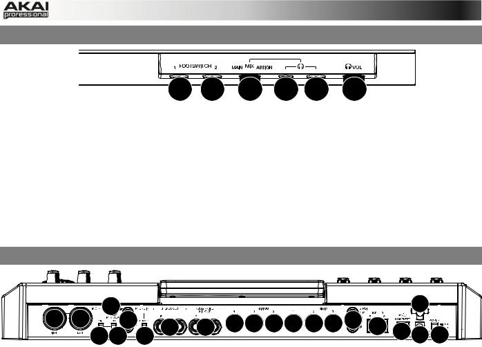
2.2 MPC RENAISSANCE: FRONT PANEL
1 |
1 |
2 |
3 |
3 |
4 |
The front panel of the MPC Renaissance
1.FOOTSWITCH INPUTS – Connect optional 1/4” TS footswitches to these inputs.
2.MIX KNOB – Use this knob to adjust the balance between the MAIN and ASSIGN signals in your headphones. The MAIN signal is the STEREO OUTS. The ASSIGN signal is the
ASSIGNABLE MIX OUTS 1 and 2.
3.HEADPHONES – Connect your headphones (not included) to one of these standard TRS outputs (1/8” or 1/4”). Use the MIX KNOB to determine what signal is heard in the headphones.
4.HEADPHONES VOLUME – Use this knob to adjust the headphone volume.
2.3 MPC RENAISSANCE: REAR PANEL
|
|
14 |
|
|
|
|
|
|
2 |
|
9 |
9 |
12 |
|
6 |
7 |
16 16 16 16 15 15 |
8 |
5 |
|
|
|
|
10 11 |
13 |
|
4 1 |
3 |
The rear panel of the MPC Renaissance
1.POWER INPUT – Connect the 12V DC – 2A power adapter (center pin positive) to this jack then into an electrical outlet.
2.POWER ADAPTER RESTRAINT – You can secure a power adapter cable to this restraint to prevent it from accidentally unplugging.
3.POWER SWITCH – Turns MPC Renaissance's power on/off.
4.COMPUTER USB PORT– Use the included USB cable to connect this high-retention-force
USB port to an available USB port on your computer. This connection allows MPC
Renaissance to send/receive MIDI and audio data to/from the MPC software.
5.USB HUB OUTPUTS – You can connect additional USB devices (controllers, hard drives, etc.) to these powered, high-speed USB 2.0 ports. In addition to being an audio interface, these ports allow MPC Renaissance to function as a powered USB hub when it is powered on.
6.STEREO OUT – Connect these 1/4" TRS outputs to your speaker system (not included). The signal sent out of these outputs is the main mix. In the MPC software, you can set what is routed to these outputs in the Program Mixer tab, by selecting OUT 1,2 as the OUT for one pad or multiple pads.
7.ASSIGNABLE MIX OUT – Connect these 1/4" TRS outputs to an external mixer (not included). The signal sent from these outputs is full-volume (0 dB). In the MPC software, you can set what is routed to these outputs in the Program Mixer tab, by selecting OUT 3,4 as the OUT for one pad or multiple pads.
8.S/PDIF IN/OUT – Use standard RCA cables to connect these jacks to devices that can send/receive digital audio.
8

9.MIC IN – Connect an external sound source or microphone to these jacks using standard 1/4" TRS or XLR cables. Make sure to set the MIC/LINE SWITCH appropriately.
10.MIC/LINE SWITCH – Set this switch appropriately for the device you connected to the MIC IN jacks. If your sound source is a microphone, set it to MIC. If your sound source is a linelevel device, like an external mixer or keyboard, set it to LINE.
11.PHANTOM POWER SWITCH – This switch activates and deactivates phantom power. When activated, phantom power supplies +48V to both MIC IN inputs. Please note that most dynamic microphones do not require phantom power, while most condenser microphones do. Consult your microphone's documentation to find out whether it needs phantom power.
12.PHONO IN – Connect these RCA inputs to an external sound source (e.g., a turntable, CD player, etc.). Make sure to set the PHONO/LINE SWITCH appropriately.
13.PHONO/LINE SWITCH – Flip this switch to the appropriate position, depending on the device connected to the AUX INPUTS. If you are using phono-level turntables, set this switch to "PHONO" to provide the additional amplification needed for phono-level signals. If using a line-level device, such as a CD player or sampler, set this switch to "LINE."
14.GROUND TERMINAL – If you connected a phono-level turntable to the PHONO IN jacks and are hearing a low hum or buzz, this could mean that the turntable is not grounded. If the turntable has a grounding wire, connect it to this terminal.
Note: Some turntables have a grounding wire built into the RCA connection and, therefore, nothing needs to be connected to the grounding terminal.
15.MIDI IN – Use a five-pin MIDI cable to connect the MIDI OUT of an optional external MIDI device to the MIDI IN of MPC Renaissance.
16.MIDI OUT – Use a five-pin MIDI cable to connect the MIDI OUT of MPC Renaissance to the MIDI IN of an optional external device.
ÂFor more information about the specifications of the MPC hardware please refer to the corresponding chapter in the Appendix section of this manual.
9
2.4 MPC STUDIO: TOP PANEL
|
|
|
|
|
3 |
4 |
1 |
2 |
|
13 |
|
|
|
|
|
|
|
|
|
|
|
|
5 |
|
|
|
|
|
|
|
|
|
|
|
16 16 16 16 17 |
||||
12 |
|
|
|
|
18 |
19 29 30 31 |
|||
|
|
|
|
|
|||||
6 |
6 |
6 |
6 |
6 |
6 |
|
|
|
|
|
|
|
|
|
24 25 26 27 28 |
||||
12 |
|
|
|
|
33 34 35 36 37 |
||||
|
|
|
|
|
|||||
|
|
|
|
|
|
|
|
|
10 |
12 |
|
|
|
|
22 |
|
8 |
|
|
|
|
|
|
|
|
|
|
|
23 |
12 |
|
|
15 |
|
21 |
5 |
|
5 |
32 |
|
|
|
|
|
|||||
|
|
|
|
|
|
|
|
|
|
|
|
|
|
|
47 |
|
7 |
|
11 |
14 |
|
|
|
|
|
|
|
|
|
46 |
|
|
|
|
43 43 45 44 44 |
||||
|
|
|
|
|
|
|
|
|
|
20 |
|
|
|
|
41 42 40 38 39 |
||||
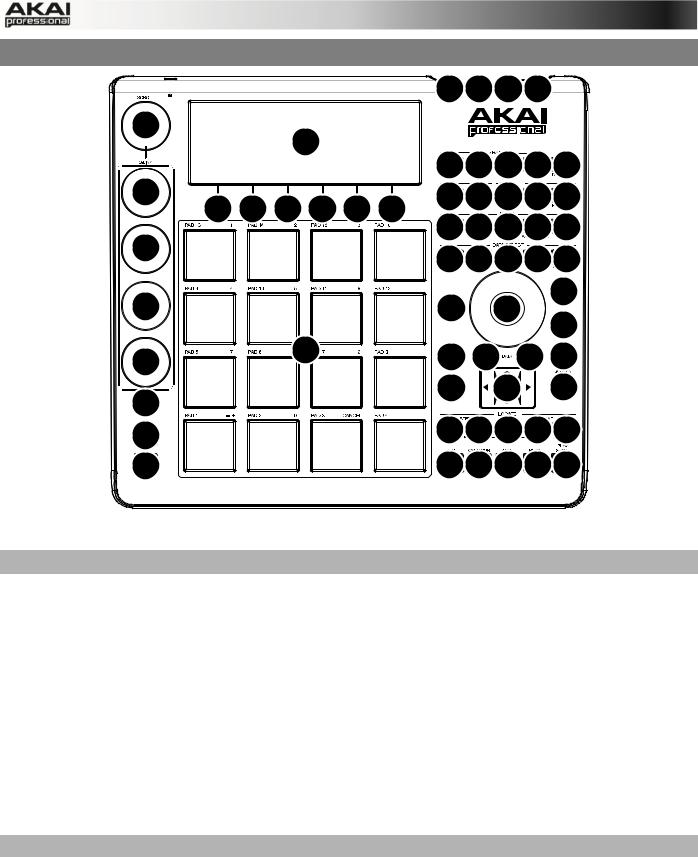
The top panel of the MPC Studio.
POWER & I/O
1.COMPUTER USB PORT– Use the included USB cable to connect this high-retention-force
USB port to an available USB port on your computer. This connection allows MPC Studio to send/receive MIDI and audio data to/from the MPC software.
2.POWER SWITCH – Turns MPC Studio's power on/off.
3.MIDI IN – Use the included 1/8"-MIDI adapter and a five-pin MIDI cable to connect the MIDI
OUT of an optional external MIDI device to the MIDI IN of MPC Studio.
4.MIDI OUT – Use the included 1/8"-MIDI adapter and a five-pin MIDI cable to connect the
MIDI OUT of MPC Studio to the MIDI IN of an optional external device.
IMPORTANT: Do NOT connect audio devices (e.g., headphones, monitors, etc.) to the 1/8"
MIDI IN or MIDI OUT jacks. Use the included 1/8"-MIDI adapters to connect MIDI devices only.
NAVIGATION / DATA ENTRY CONTROLS
5.DISPLAY – This LCD shows all the information relevant to MPC Studio's current operation. Much of this information is also shown in the software. Use the CURSOR BUTTONS to navigate through the display, and use the DATA DIAL, and -/+ buttons to adjust the currently selected setting/parameter. Use the MODE buttons to change what page is shown, and use the F-BUTTONS to change what tab is shown.
Press and hold SHIFT and turn the DATA DIAL to adjust the contrast of the DISPLAY.
6.F-BUTTONS – Press one of these buttons to select its corresponding tab, shown above the button in the display.
10
7.CURSOR BUTTONS – Use these buttons to navigate through the fields of menus and options shown in the DISPLAY.
8.DATA DIAL – Use this dial to scroll through the available menu options or adjust the parameter values of the selected field in the DISPLAY.
9.-/+ – Press these buttons to increase/decrease the value of the selected field in the display.
10.NUMERIC – If the selected field in the DISPLAY is a number, you can press NUMERIC and use the pads as a standard numeric keypad to enter a value. The numbers are printed in green above the pads.
11.UNDO / REDO – Press this button to undo your last action. You can undo up to 200 actions. Hold down SHIFT and press this button to redo the last action you undid.
PAD / Q-LINK KNOB CONTROLS
12.Q-LINK KNOBS – Use these touch-sensitive knobs to adjust various parameters and settings. The knobs can control one column of parameters at a time. Use the SCROLL
KNOB above them to change which column of parameters they currently control.
13.SCROLL KNOB – Use this knob to change which column of parameters the Q-LINK KNOBS currently control.
14.Q-LINK TRIGGER – Hold this button down, then touch one of the Q-LINK KNOBS to make that knob's parameter's value jump to its minimum or maximum (depending on the Trig parameter in the software).
15.PADS – Use these pads to trigger drum hits or other samples in your software. The pads are velocity-sensitive and pressure-sensitive, which makes them very responsive and intuitive to play. The pads will light up different colors, depending on how hard you play them (ranging from yellow at a low velocity to red at the highest velocity). To disable (or reenable) these lights, press PAD ASSIGN then F6 (Velo Col).
If the selected field in the DISPLAY is a number, you can press NUMERIC and use the pads as a standard numeric keypad to enter a value. The numbers are printed in green above the pads.
16.PAD BANK BUTTONS – These 4 buttons switch among Pad Banks A – H (press and hold
SHIFT to access Banks E – H). Between these 8 banks with 16 pads per bank, you can access up to 128 MIDI events using the pads.
17.PAD ASSIGN / PAD COPY – Press this button to assign a sample to a pad. In the display, the 4x4 grid that appears represents the 16 pads. Use the CURSOR BUTTONS to navigate through the grid, and use the DATA DIAL or -/+ buttons to select a Program (when the Program field is highlighted) or a sample (when a pad is highlighted).
Hold down SHIFT and press this button to copy the samples and parameters from one pad to another. Use the CURSOR BUTTONS to select the From Pad ("source") or To Pads ("destination") field and hit a pad to select it (you can copy to multiple pads). Use the F- BUTTONS to confirm or cancel the operation.
18.FULL LEVEL / HALF LEVEL – Press this button to activate/deactivate Full Level. When activated, the pads always play back at a maximum velocity (127), no matter how hard or soft you hit them.
Hold down SHIFT and press this button to activate/deactivate Half Level. When activated, the pads always play back at half-velocity (63).
11
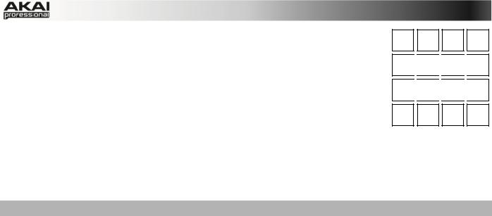
19.16 LEVEL – Press this button to activate/deactivate 16 Level. When 103 111 119 127 activated, the last pad that was hit will be temporarily copied to all 16
pads. The pads will now output the same note number as the initial pad, but a selectable parameter will be fixed at the values shown in the diagram on the right, regardless of how hard you hit them. The available parameters are velocity, tuning, filter, layer, attack or decay.
71 
 79
79 
 87
87 
 95
95
39 
 47
47 
 55
55 
 63
63
20. NOTE REPEAT / LATCH – Hold this button down and press a pad to 7 retrigger that pad's sample at a rate based on the current Tempo and
Time Correct settings (the available Time Correct settings will appear in the display, which you can select with the F-BUTTONS). Hold down SHIFT and press this button to latch the
Note Repeat feature. When latched, the button does not need to be held down for Note Repeat to be activated. Press NOTE REPEAT once more to unlatch it.
MODE / VIEW CONTROLS
21.SHIFT – Hold this button down to access some buttons' secondary functions (indicated by orange writing).
22.MAIN / TRACK – Press this button to view the Main screen in the display and software. Hold down SHIFT and press this button to view the Track View screen in the display and software.
23.BROWSER / SAVE – Press this button to view the file browser in the display. Hold down
SHIFT and press this button to save the current Project (including its samples, Programs,
Sequences, and Songs).
24.PROG EDIT / Q-LINK – Press this button to view the Program Edit screen in the display and software. Hold down SHIFT and press this button to assign a parameter to a Q-LINK
KNOB: use the CURSOR BUTTONS to select the desired Q-LINK KNOB, then use the
DATA DIAL or -/+ buttons to select the desired parameter.
25.PROG MIX / TRACK MIX – Press this button to view the Program Mixer screen in the display and software. Hold down SHIFT and press this button to view the Track Mixer screen in the display and software.
26.SEQ EDIT / EFFECTS – Press this button to enter Sequence Edit mode. Hold down SHIFT and press this button to enter Effects mode, where you can select and route effects as well as edit effects' parameters.
27.SAMPLE EDIT / SAMPLE REC – Press this button to view the Sample Edit screen in the display and software. Hold down SHIFT and press this button to view the Sample Record screen in the display and software.
28.SONG / OTHER – Press this button to view the Song screen in the display and software. Hold down SHIFT and press this button to enter Other mode, which allows you to set: the minimum number of taps for the TAP TEMPO button; pad threshold, sensitivity, and curve; the footswitches' messages; and the Program Change target.
29.STEP SEQ – Press this button to view the Step Sequence screen in the display and software.
30.NEXT SEQ – Press this button to view the Next Sequence screen in the display and software.
31.TRACK MUTE / PAD MUTE – Press this button to view the Track Mute screen in the display and software. Hold SHIFT and press this button to view the Pad Mute screen in the display and software.
12

32.WINDOW / FULL SCREEN – When this button is lit, it means the selected field in the display contains additional functions; press this button to access them. Use the F-
BUTTONS, CURSOR BUTTONS, and DATA DIAL or -/+ buttons to execute (or cancel) these additional functions.
Hold SHIFT and press this button to switch between Full Screen and Half Screen modes. In Full Screen mode, the workspace occupies the whole screen. In Half Screen mode, the parameter controls (Q-Link knobs, pads, Sequence and Track information, Project
Information, etc.) are shown underneath the workspace.
33.PROJECT / FOLDER 1 – Press this button to view only Project files in the File Browser.
Hold down SHIFT and press this button to select the Browser's Folder 1 shortcut.
34.SEQUENCE / FOLDER 2 – Press this button to view only Sequence files in the File Browser. Hold down SHIFT and press this button to select the Browser's Folder 2 shortcut.
35.PROGRAM / FOLDER 3 – Press this button to view only Program files in the File Browser. Hold down SHIFT and press this button to select the Browser's Folder 3 shortcut.
36.SAMPLE / FOLDER 4 – Press this button to view only Sample files in the File Browser.
Hold down SHIFT and press this button to select the Browser's Folder 4 shortcut.
37.NO FILTER / FOLDER 5 – Press this button to view all files in the File Browser. Hold down SHIFT and press this button to select the Browser's Folder 5 shortcut.
TRANSPORT / RECORDING CONTROLS
38.PLAY – Press this button to play the Sequence from the audio pointer's current position.
39.PLAY START – Press this button to play the Sequence from its start point.
40.STOP – Press this button to stop playback.
41.REC – Press this button to record-arm the Sequence. Press PLAY or PLAY START to start recording. Recording in this way (rather than using OVERDUB) erases the events of the current Sequence. After the Sequence plays through once while recording, Overdub will be enabled.
42.OVERDUB – Press this button to enable Overdub, which allows you to record note events in a Sequence without overwriting any previously recorded note events. You can enable
Overdub either before or during recording.
43.< / > ( |< / >| ) – Use these buttons to move the audio pointer left/right, one step at a time.
Hold LOCATE and press one of these buttons to move the audio pointer to the previous/next event in the Sequence Grid.
44.<< / >> (START/END) – Use these buttons to move the audio pointer left/right, one bar at a time. Hold LOCATE and press one of these buttons to move the audio pointer to the start or end of the Sequence Grid.
45.GO TO – Hold this button down to activate the secondary functions of the < / > and << / >> buttons (i.e., |< / >| and START/END, respectively).
46.ERASE – As a Sequence is playing, hold this button down and press a pad to delete the note event for that pad at the current playback position. This is a quick way to delete note events from your Sequence without having to stop playback.
47.TAP TEMPO – Press this button in time with the desired tempo to enter a new tempo (in BPM) in the software.
13

3. INSTALLING THE MPC SOFTWARE
This chapter explains how to install the MPC software including the plugin version on your computer. It also guides you through the process of authorization.
3.1 SYSTEM REQUIREMENTS
In order to be able to use the MPC software, you will need at least:
Windows PC:
•Windows 7 (32or 64-bit)
•2 GHz Pentium 4 processor or better (multi-core recommended)
•2 GB RAM (4 GB recommended)
•14 GB free hard disk space
•Dual Layer DVD-ROM drive
Mac:
•Mac OS X 10.6.8 or above
•2 GB RAM (4 GB recommended)
•14 GB free hard disk space
•Dual Layer DVD-ROM drive
ÂPlease also check the system requirements of your host application!
14

3.2 INSTALLATION UNDER WINDOWS
How to install the MPC software.
Installation from DVD:
1.Start your computer and launch your operating system. Insert the MPC DVD into your
DVD-ROM drive. If you have enabled the Autostart function in Windows, the Installer will start automatically and you can proceed with Step 5 below. If not, please proceed as follows:
2.Launch the Explorer or open the window "My Computer."
3.Double-click on the icon for the drive that holds the MPC DVD.
4.Double-click on the MPC Installer icon. This launches a special installation program.
5.Follow the on-screen instructions.
ÂAfter installing the MPC software, you need to unlock the program on your computer. Please refer to the chapter "Unlocking the MPC Software."
Installation of a downloaded Installer File:
1.Refer to the folder where the downloaded MPC zip archive is located.
2.Double-click on the archive file to extract it.
3.Double-click on the MPC Installer icon. This launches a special installation program.
4.Follow the on-screen instructions.
ÂAfter installing the MPC software, you need to unlock the program on your computer. Please refer to the chapter "Unlocking the MPC Software."
15

3.3 INSTALLATION UNDER MAC OS X
How to install the MPC software:
Installation from DVD:
1.Disable any system activity monitoring software or extension. Then insert the MPC DVD into your computer’s DVD drive.
2.If required, double click on the MPC icon to open the DVD window.
3.Double-click on the MPC Installer icon to load the installation software.
4.Follow the on-screen instructions.
ÂAfter installing the MPC software you need to unlock the program on your computer. Please refer to the chapter "Unlocking the MPC Software."
Installation of a downloaded Installer File:
1.Refer to the folder where the downloaded MPC zip archive is located.
2.Double-click on the archive file to extract it.
3.Double-click on the MPC Installer DMG icon. This launches a special installation program.
4.Follow the on-screen instructions.
ÂAfter installing the MPC software you need to unlock the program on your computer. Please refer to the chapter "Unlocking of the MPC Software."
16
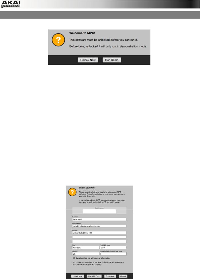
3.4 UNLOCKING THE MPC SOFTWARE
You’ll need to unlock your MPC software before using it. Follow these steps to unlock it:
1.Connect your MPC hardware to a USB port on your computer. If you are using MPC
Renaissance, connect it to a power source, too.
2.Power on the MPC hardware.
3.Open the MPC software.
4.In the dialogue box that appears, click Unlock Now.
5.Enter your information in the window that appears.
6.If your computer is connected to the Internet, click Unlock Now, and enjoy your MPC!
If your computer is not connected to the Internet, follow these additional steps:
7.Click Use Web Form.
8.The window that appears will have your name, serial number, and software ID number. Click Save Details to save this information as a .txt file, or copy the information from each field into another file of your choosing.
9.On a computer connected to the Internet, go to http://authorizations.akaipro.com/MPC, enter the copied information, and click Unlock My MPC.
10.Copy the unlock code from the window that appears.
11.In your MPC software, go to the window from Step 5 and click Enter Code.
12.Enter your name and the unlock code generated by the webpage.
13.Click Unlock, and enjoy your MPC!
17
4. QUICK START TUTORIAL
This Quick Start Tutorial was written to help you to familiarize yourself with the MPC. In order to get the most out of this tutorial, we recommend reproducing each of the described steps.
The MPC hardware display reflects what it's controlling in the software, but due to space and character limitations, the hardware display is slightly different (e.g., parameter names may be abbreviated, the layout may be different or spread across multiple tabs, etc.).
XYou can navigate through the MPC hardware display by using the MPC hardware's cursor buttons. When a parameter is selected, you can change it by turning the hardware's data dial or using the -/+ buttons.
XWhen the MPC hardware screen shows a series of parameters that can't be selected with the cursor buttons, that means it is showing you what the Q-Link knobs are controlling. Touch a Q-
Link knob, and the parameter's name and setting will appear in the upper right corner of the hardware display. Turn the knob to adjust it (If the Q-Link knob does not control any parameter in the display, this area will show the Q-Link knob number and no text).
ÂMPC Studio users: MPC Studio's Q-Link knobs control one column of parameters at a time. Whenever this manual instructs you to use the Q-Link knobs to adjust parameters, you can use the SCROLL knob (above the Q-Link knobs) to move through the different columns.
On the following pages we will create a short song to show you important aspects of using the
MPC software in conjunction with the MPC hardware. Let’s get started!
4.1FIRST START
•Make sure that the MPC hardware driver and software are both properly installed on your computer.
•Connect your MPC hardware to your computer with a suitable USB cable and switch it on.
After that, start the MPC software.
Now you're ready to go!
4.2 FEEDING THE MPC SOFTWARE
Let’s start with a simple drum set.
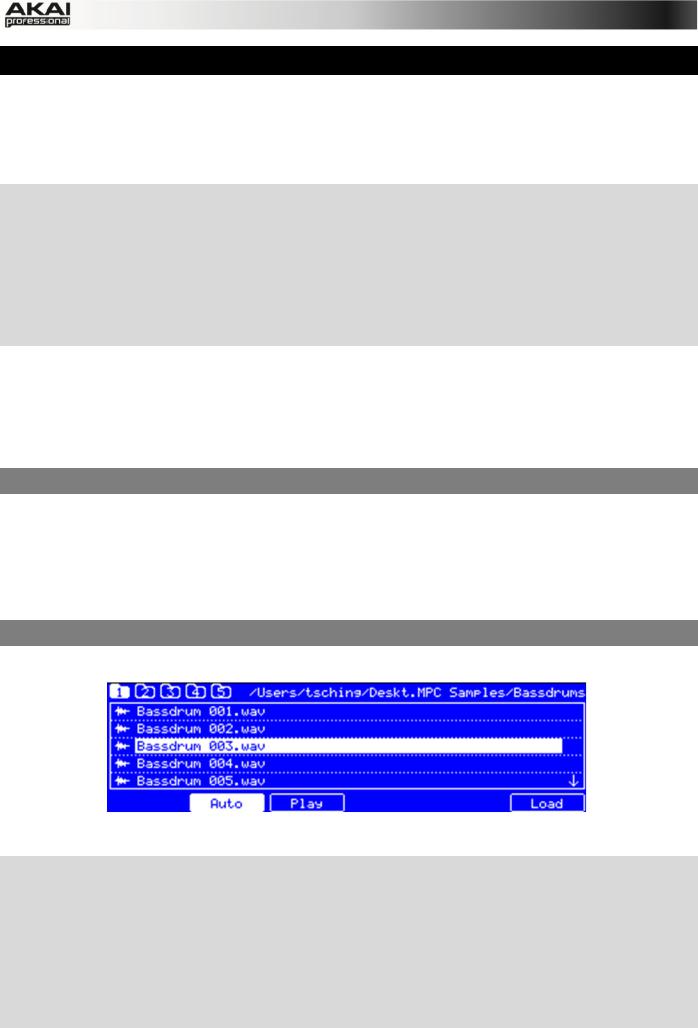
The Browser display of the MPC hardware
XClick on the BROWSER button of your MPC hardware and use the cursor down button to navigate through your hard disk folders. To enter a selected folder, click on the right cursor button to open it. Navigate to where your drum sounds are located.
XTo preview a selected sound, click on the F3 button (Play). You can also activate the Auto Preview option with the F2 button (Auto).
XFirst, let’s load a bass drum. Hit Pad 1 to select it. The pad will be lit in green. Navigate to a bass drum sample you like and click on the F6 button (Open) to assign it to the selected pad. Now the bass drum sample can be played with Pad 1.
18

XTo create a simple drum set, we repeat the steps described above for other pads. We recommend to load a snare drum on Pad 2, a closed hi-hat on Pad 3 and an open hi-hat on
Pad 4. Feel free to add a crash sample to Pad 5.
Now you're ready to record a simple drum pattern!
4.3 RECORDING A DRUM PATTERN
Let's start to record a drum pattern.
XPress the REC button of your MPC hardware to activate the recording mode. To start the actual recording, press the PLAY button. The precount starts to count one measure. We recommend recording the drum sounds one after the other, especially if you are not familiar with playing on the pads.
XPlay a simple bass drum pattern. The initial measure length is 2 bars. After the two bars, the pattern plays again from the beginning and keeps looping. Don't stop the recording!
XPlay a snare drum pattern, then a hi-hat pattern.
XPress the STOP button to finish the recording.
XThe note events you just recorded will automatically be placed in the grid, in this case, on 16th notes.
XIf you want to repeat the recording, keep in mind that the pads you play in your new recording will automatically replace existing notes played with the same pads. To prevent this, you can use the OVERDUB function, which enables you to record additional note events to an existing pattern. When the sequence loops around, the MPC is automatically placed in OVERDUB mode.
XThe MPC hardware's UNDO button can be used differently while in Record Mode. Normally, pressing UNDO will undo just the last event. When there is an event to undo, the UNDO button will be lit solid. While recording, the UNDO button will flash. In this case, pressing UNDO will erase all events from that recording (i.e., since the PLAY or PLAY START was pressed).
XHow about a crash cymbal? Let's create it directly in the MPC software by clicking on the desired position in the grid, in the same row as the crash sample.
Does your drum pattern sound OK? If not, keep on reading!
4.4 ORGANIZATION & EDITING
We recommend doing some naming and editing before recording other patterns.
X Click on the MAIN button of your MPC hardware to enter Main Mode.
Let’s use the MPC software, which is much better for editing.
The pad assignment of your drum sounds is arranged in a Program. Let’s rename the exisiting Program as we will want to create more Programs later on. Right-click on the Program 01 in the PROJECT INFORMATION in the right section of the Main area and select the Rename option. Name the program (e.g. Drums) and click OK.
Right-click on the name of a sample (e.g. the bass drum), and select Rename. Enter a suitable name for the sample (e.g., "Bass Drum 1" or "Kick1"). Repeat this for the other samples in the Program. This will help keep your Program organized as you add more and more sounds to it.
In the Grid, you can see your recorded note events. Click and hold on a note to move it to a different position. By default, you can only position notes by quantization values, defined by the previously set TIME CORRECT value. You may change the value by clicking on the TIME
19
CORRECT pop-up menu. We recommend to work with 8 or 16 values. Hold down your keyboard's SHIFT and use the ARROW keys to nudge events without restricting to the grid.
Hold down the CTRL key (PC) or Command key (Mac) and click-and-drag a note to copy it.
Double-click on a note to delete it.
Velocity data can be easily edited in the velocity lane below the Grid. Click on a note event (or multiple note events) or place the mouse over a velocity bar in the lane. A small round handle will appear at the top of the velocity bar. Move the mouse vertically to change its value.
Satisfied with your work? Let’s keep on making some basic sound edits.
4.5 BASIC SOUND EDITS
What about levels and effects? Don’t worry, we’ll get there in time!
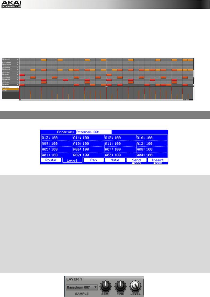
The Program Mixer display of the MPC hardware
XPress the PROG MIX button of your MPC hardware to enter Program Mixer Mode.
XPress the F2 button (Level) to control the volume for each pad. You can use the Q-Link knobs of your MPC hardware as well as the corresponding fader in your MPC software. Adjust the levels of each pad to suit your taste.
XPress the F3 button (Pan) to control the stereo panorama for each pad. You can use the Q-
Link knobs of your MPC hardware as well as the corresponding PAN knob in your MPC software. We recommend spreading the panning of the bright sounds a little.
XThe snare drum needs a small amount of reverb to give it a more spatial sound. Press the F6 button (Insert 1) to enter the insert effect page. Use the cursor buttons to navigate to the pad (here: A02) where your snare sample is located. With the data dial, you can now select the desired effect. Let’s try the Reverb Medium.
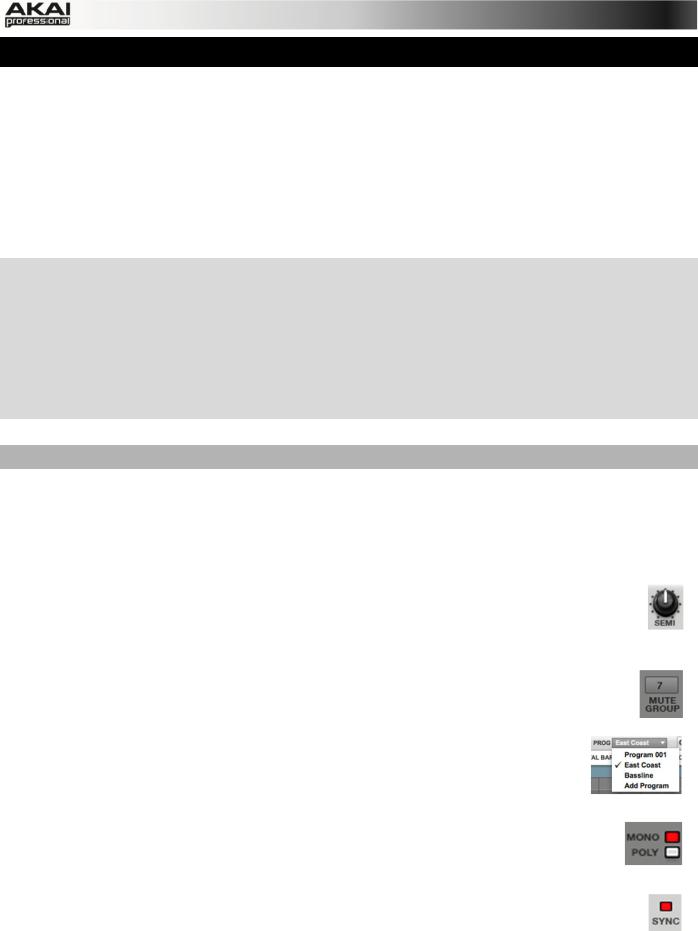
XCould the bass drum use some tuning? No big deal: press the PROG EDIT button and hit Pad 1 to select the bass drum. Click on F2 (Samples) and use the Q14 and Q15 Q-Link knobs to tune the sound. You can also use the corresponding SEMI and FINE parameter in the Layer section of the MPC software.
We’re on the move now… Time to add a new sound!
20
4.6 THE BASSLINE TRACK
To complete our musical experiment, we need a bassline. In this case, it is important to be able to play a bass sound chromatically. How does that work?
First of all, we need to select a new track. Go back to Main Mode and select Track 02 in the
TRACK pop-up menu above the Grid.
XIn the MPC hardware you have to press the MAIN button. With F4 (Track+) you can switch to the next track.
This new and empty Track should be assigned to a new Program. You can do this in Program Edit Mode. Click on the PROG pop-up menu above the Grid and select the Add Program option. A new window opens. Enter a name, e.g. Bass, and select KEYGROUP as the Program Type. This is necessary because we want to play the bass sound chromatically with the drum pads.
Now let’s load a bass sound. We will use the Browser in the MPC software.
Click on the file browser’s pop-up menu for an overview of your hard disk structure. Locate and select a bass sample. You can double-click on any displayed folder to open it. Click on the Preview button to preview any selected audio sample. If you found a sample to your liking, double-click it to add it to the MPC software’s currently loaded Project. Keep in mind that the sample is not yet assigned to a pad.
XPress the PROG EDIT button of your MPC hardware to enter Program Edit Mode, if not selected already.
In the Layer section click on the LAYER 1 pop-up menu and select the bass sample you just loaded into the MPC software’s currently loaded Project. In this list you will also find your drum samples. Keep in mind that you are working with a KEYGROUP program, so the selected sample is playable across all pads.
XPress the PAD BANK D button of your MPC hardware to switch to pad bank D and hit Pad 13.
You should hear the bass sample played back with its original pitch. You can use the other pads to play your sample chromatically.
To step it up even further, we want to add a second layer. The idea is to have a bass sample that sounds different when played at a higher velocity. Go back to the File Browser and choose a different bass sample that sounds similar
but a little bit brighter to the loaded one.
Double-click on it!
Back in the Layer section, click on the
LAYER 2 pop-up menu and select the new bass sample. If you hit a pad, both samples will be played at once. Maybe
you find that new sound interesting as it is right now, but let’s go further!
Use the VELOCITY slider of Layer 1 and Layer 2 to create a sound with the velocity range of Layer 1 ranging from 0 to 80 while Layer 2 covers within the range of 81 to 127.
Now when you hit a pad, the lower velocities will trigger Layer 1 only, while higher velocities play Layer 2 only.
Now let’s record a bassline. Prepare your recording as described above and record some bass notes. You can edit your recording just like we’ve done earlier.
21
Finally, let’s tweak the bassline sound. This can be done in the FILTER section of the Program Edit menu. Back to the MPC hardware!
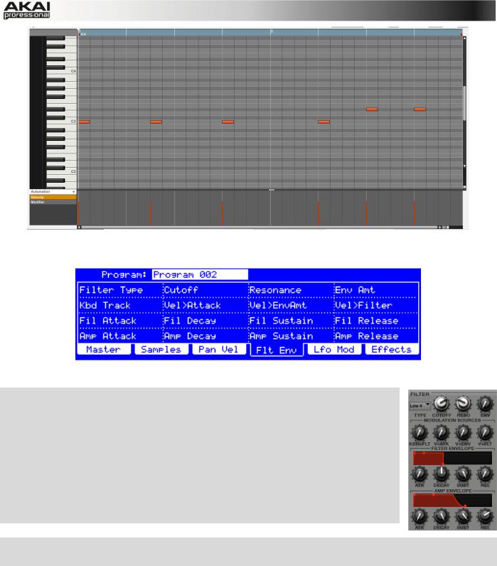
The Filter and Envelope display of the MPC hardware
XPress the PROG EDIT button of your MPC hardware to enter Program Edit Mode. Click on the F4 button (Flt Env) to enter the Filter page.
XUse the Filter Type option to select a suitable filter type. We recommend to work with the Low 4 type for a start.
XTurn the Cutoff and Resonance knobs (Q-Link knobs Q14 and Q15) until your bass sample sounds perfect to you.
XUse the Q-Link knobs Q1 to Q4 to set the amplifier envelope. This controls the overall level characteristics of the sound.
XDo you want to add some effect, e.g. Chorus? Press F6 (Effects) and select the desired effect type for your bassline. (Remember to turn the Inserts parameter to "ON.")
Now we've created a simple drum pattern with a bassline. But there’s much more!
22
4.7 WORKING WITH A DRUM LOOP
Modern music producers often use drum loops to add grit and dimension to programmed beats.
And this is exactly what we want to do now!
Use the FILE BROWSER to locate a drum loop on your hard disk. It is not necessary that it does match the tempo of your recorded tracks. Double-click the desired drum loop so that it is added to the currently selected Program.
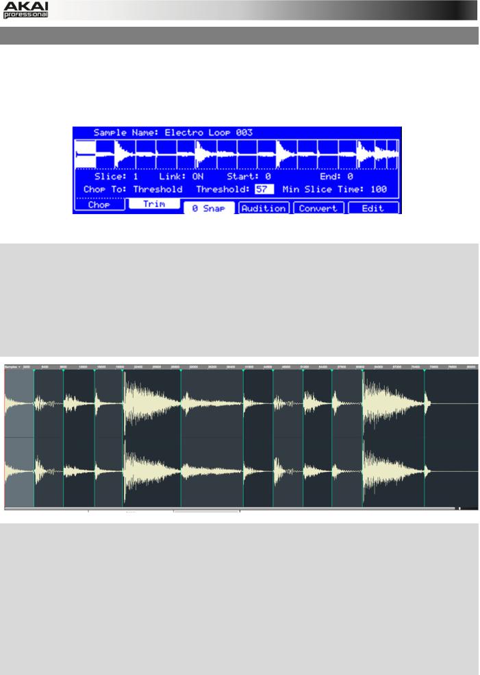
The Chop mode of the MPC hardware’s Sample Edit page
XPress the SAMPLE EDIT button of your MPC hardware to enter Sample Edit Mode.
XUse the data dial to select the loaded drum loop. You can scroll through all loaded samples seen the top of your MPC hardware display.
XPress F1 (Chop) to enter the Chop mode. We are going to cut the drum loop into slices.
XUse the cursor to navigate to the Threshold parameter and select a desired value. The higher the selected value, the more slices will be created. Make sure to choose a threshold value so that every transient peak of the drum loop is shown with a slice line.
XHint: Click on F4 (Audition) to play the created slices via the pads. Each slice is automatically assigned to a pad, starting from Pad A01 with Slice 1 and so on.
XNow we’ll create a new Program containing all created slices as single samples as well as the corresponding note events to playback these slices in a row. This is very easy!
XPress F5 (Convert) to enter the Convert Slices page. Use the cursor to navigate to the following parameters and select the value indicated as follows: Convert to Sliced Samples,
Crop Samples to On, Create New Program to On, Create Events to On and finally the
Number Of Bars to the bar length of your recorded track, in our example that is 2. Press F6
(Do It) to proceed!
XStart the playback and listen how the drum loop matches your song tempo now.
23
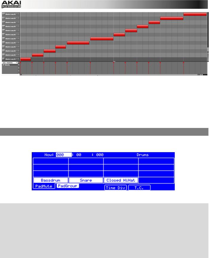
You can also edit the note events of the drum loop slices. Enter Main Mode to do this. A new Track with the note events playing their corresponding slices has been automatically created. Use the Time Correct function (i.e., in the Time Correct menu) to quantize the note events to an exact timing. You can also rearrange the note events, thus creating a new playback order for the slices. It is also possible to edit each slice / sample in Program Edit Mode. You can add effects for slices or use the filter function to change the frequency range of a selected slice. There are almost no limits to what you can do.
4.8 PAD AND TRACK MUTE
In this section, we will mute different pads and tracks to see what the sequence sounds like without some of these parts.
The Pad Mute display of the MPC hardware
XFirst, go back to your basic Drum track.
XPress and hold the SHIFT button on your MPC hardware and press the TRACK MUTE/ PAD MUTE button to enter Pad Mute Mode.
XYou can now mute a pad by pressing it once. The muted pad will be lit red. This is useful for listening to a sequence without the muted sample.
XTo mute pads on another track, press SHIFT + MAIN/ TRACK and click on F3 (Track-) or F4 (Track+) to switch between the recorded tracks. Press SHIFT + TRACK MUTE/ PAD MUTE again to perform the desired mutes.
You can also mute entire tracks by using the Track Mute function.
24
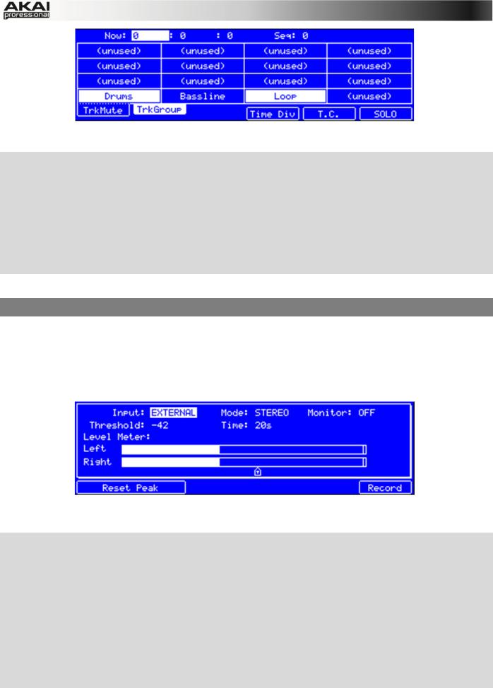
The Track Mute display of the MPC hardware
XPress the TRACK MUTE button on your MPC hardware to enter Track Mute Mode.
XYou can now mute a Track by hitting the corresponding pad once. The muted pad is lit red.
XIf you want to mute a track only at precise note intervals ("quantizing" your mutes, essentially), you can set a musical timing value by clicking on the F4 button (Time Div.). Use the data dial to set a musical value, for example 1 bar. Click on F4 (Close) to close the page. When you now hit a pad while in Track Mute mode, the mute will occur precisely at the beginning of the following bar. This lets you test musical combinations of patterns – the stage preliminary to building a song structure.
Now, let's add some "human feeling" to our song.
4.9 RECORD AND EDIT A SAMPLE
Let’s record some vocals with a connected microphone.
ÂMPC Studio users: This section describes recording using MPC Renaissance as your sound card. MPC Studio can't be used in this way, but you can use a separate audio interface connected to your computer to record audio.
The Sample Record display of the MPC hardware
XPress and hold the SHIFT button on your MPC hardware and click on the SAMPLE EDIT/ SAMPLE REC button to enter Sample Record mode.
XConnect a suitable microphone to a MIC IN jack of your MPC Renaissance. Make sure to set the input switch to MIC.
XSet the MIC IN/PHONO IN switch on the top panel of the MPC hardware to MIC/LINE and turn up the REC GAIN dial. In the MPC software you should now see the input signal. Make sure that the signal gain does not exceed the maximum level (the top input level display segment should be hardly lit).
XUse the cursor buttons to navigate to the Threshold parameter and set it to a fairly low level, e.g. -70 dB.
25
XNow press F6 (Record) and shout something like "Uhhh" or "Yeah!" into the microphone. The recording procedure starts immediately when the input signal level reaches the threshold value.
XNow press F6 (Stop) again, to stop recording.
If you're happy with your recording, please name the new sample in the MPC software in the small window, which will pop up automatically after finishing the recording procedure. Let’s call it
"Vocal" for now. You should also assign the sample to an unused pad, e.g. Pad 13. Hit it to assign the sample! After that, click on Keep.
Now we can edit our newly recorded sample. Select the sample in the PROJECT INFORMATION section and right-click on it. In the pop-up menu, choose the option Edit. Sample Edit Mode will open.
XPress F2 (Trim) on your MPC hardware to enter the trim mode for editing.
XUse the Q-Link knobs Q1, Q5, Q9 or Q13 to define a suitable start point of your sample. With
Q3, Q7, Q11 or Q15 you can define a suitable end point.
XTo hear your edits, press the Pad A15 to play the sample from the new start point to the new end point.
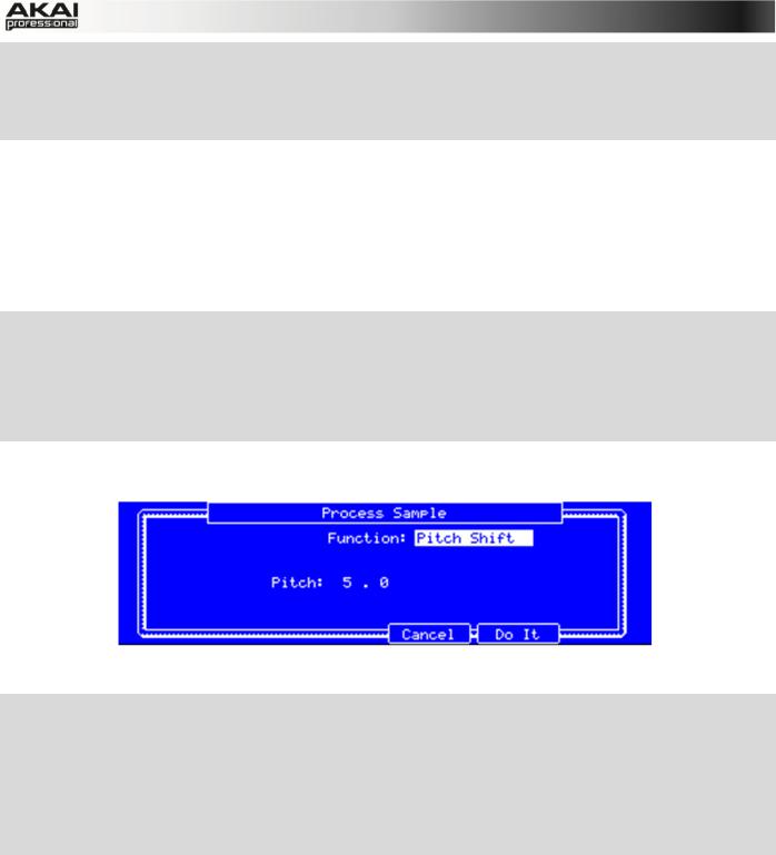
Finally, let’s apply some transformations to the sample. The MPC software offers some great options.
The Process Sample display of the MPC hardware
XPress F6 (Edit) on your MPC hardware to enter the Process Sample page.
XWith the data dial you can select the desired option. Let’s try some Pitch Shift to change the overall pitch of your sample.
XUse the cursor to navigate to the Pitch parameter and set it to 5.0. This will transpose the sample by 5 semitones but will not affect the length of the sample.
XPress F5 (Do It) to finalize the edit process.
Sounds cool, so let's include the new sample in your track. In the next chapter, we’ll show you an easy way to record note events.
26
4.10 STEP-BY-STEP WITH STEP RECORDING
You’ve already learned how to record note events on a track. But there’s an easier way to do it.
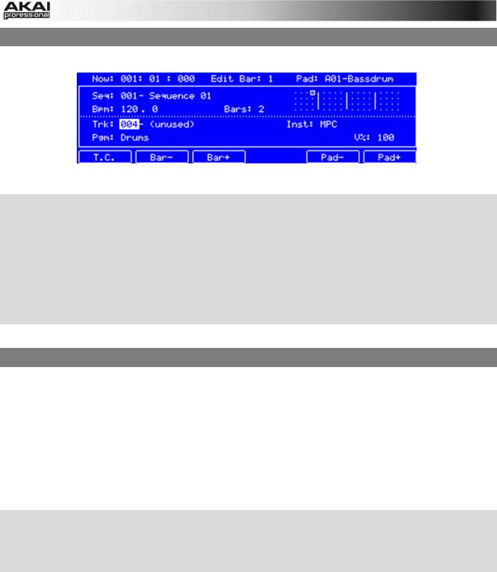
The Step Seq mode display of the MPC hardware
XIt makes sense to use a new track, so use the cursor buttons to navigate to the Trk parameter to select an unused track. Let’s say Track 04. Navigate to the Bars parameter (the number of bars for the sequence) and set it to Bars: 1.
XPress the STEP SEQ button on your MPC hardware to enter the Step Seq mode.
XPress the PLAY button to start your sequence.
XHit one of the 16 pads to insert a note event in the new track. You can instantly hear and see new events. The green cursor is indicating the current time and the pads represent steps of the timing correct. For example, hit pads 1, 5, 9 and 13 to create a four-on-the-floor kick.
Pretty easy, right?
4.11 AUTOMATION
Now, let's add some spice to our sequence. First, we'll add an effect to our new recorded sample, e.g., a reverb.
In the MPC software, click on the Main tab to open Main Mode. Locate the pad that shows the name "Vocal", indicating that our sample has been assigned to it.
In the Q-Link section, click on the PRG button. Turn Q-Link knob Q1 to activate it for assignment. Now click on the PAD field to select the pad that "Vocal" is assigned to. In the PARAM field, select Filter Cutoff as parameter. In the CHANGE field, select Real Time as the parameter. Do the same steps for Q-Link knob 2: assign it to the "Vocal" pad, and select Real Time as the CHANGE parameter, but select Filter Reso (resonance) for PARAM.
XPress the OVER DUB button on your MPC hardware to arm your automation recording. Press PLAY to start it.
XUse Q-Link knobs Q1 and Q2 to record filter movement as desired. After that, press STOP to finish the automation recording.
Want to see what you’ve recorded?
In the MPC software, to the left of the velocity lane under the Grid, click the Automation menu, select Real Time, and select RT Filter cutoff and RT Filter resonance. The parameters will appear below it. Click either one to show its automation data. By clicking on an automation anchor point, you can edit the automation.
27
4.12 CREATING A SONG
In the last few chapters, we have learned how to record tracks. But how can we create a song from our track recordings? The next steps will guide you!
Make sure that you have recorded some tracks. All of your tracks combined are called a Sequence. You can create a new Sequence by clicking on the Main tab button and use the SEQ pop-up menu above the Grid to select a new, empty sequence.
Within a Sequence, you can record notes and automation data. In addition, you can use the copy and paste functions from the Edit menu to copy existing tracks to new ones.
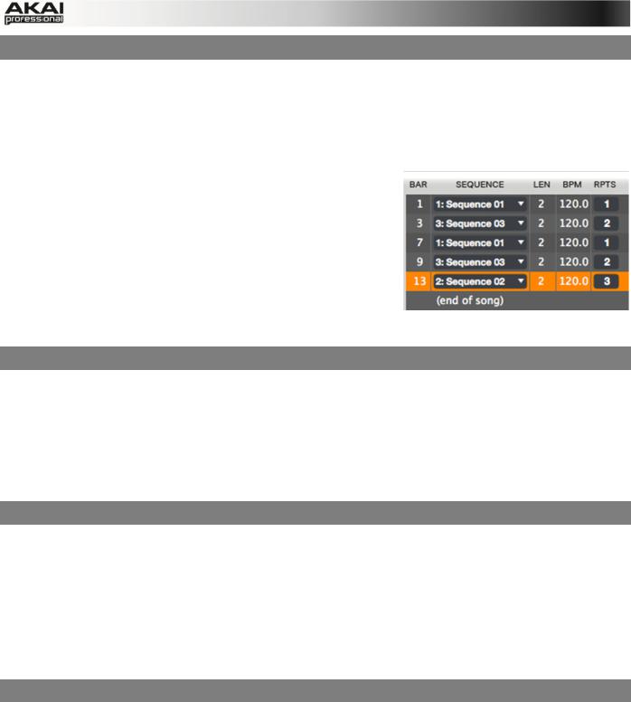
Click on the Song tab to open Song Mode. Each Sequence is assigned to a pad. Click and hold a pad with the desired
Sequence, then drag and drop it onto the Sequence Playlist to the left of the pads. You can also drop it onto the workspace above the pads, if you prefer working in a horizontal arrangement. You can easily enter repeats
(RPTS) or drag and drop sequences in the playlist to exchange them.
4.13 EXPORTING THE WHOLE SONG
Want to share your new song with your friends?
All you need to do is to export the complete song. Open the File menu and navigate to Export. Here you need to select As Audio Mixdown.
In the Audio Mixdown window, you can select your mixdown settings. Set the length of your song from Start to End. As the song will most probably be uploaded to the internet, select the mp3 file format option. Choose a path for saving the file and click OK to start exporting the song.
4.14 WORKING WITH THE MPC AS AN INSTRUMENT PLUGIN
Are you working with an audio sequencer? Then you can integrate the MPC software as an instrument plugin in addition to your production tools.
ÂIf you want to know how to load an virtual instrument in your sequencer, please refer to your sequencer’s manual.
Once the MPC software plugin is loaded, it automatically synchronizes with your host sequencer software. When you start your sequencer, the MPC software starts to play back at the same time.
The MPC plugin offers the same features and functionality as the standalone software version.
IMPORTANT!
ÂFor more information about all the features and functionality of the MPC software, we recommend reading the rest of this manual.
28
5. THE MPC SOFTWARE IN DETAIL
The following chapters explain the MPC software in detail.
ÂWhenever the MPC hardware can be used to control a parameter or a function, this is explained separately in a light-grey box marked by an arrow on its left side.
ÂWe strongly recommend using the MPC hardware to control the software as its intuitive and fast operation will greatly enhance your creative workflow.
The MPC hardware display reflects what it's controlling in the software, but due to space and character limitations, the hardware display is slightly different (e.g., parameter names may be abbreviated, the layout may be different or spread across multiple tabs, etc.).
XYou can navigate through the MPC hardware display by using the MPC hardware's cursor buttons. When a parameter is selected, you can change it by turning the hardware's data dial or using the -/+ buttons.
XWhen the screen shows a series of parameters that can't be selected with the cursor buttons, that means the screen is showing you what the Q-Link knobs are controlling. Touch a Q-Link knob, and the parameter's name and setting will appear in the upper right corner of the hardware display. Turn the knob to adjust it (If the Q-Link knob does not control any parameter in the display, this area will show the Q-Link knob number and no text).
Hints for editing the MPC software with your computer mouse
If you use a computer mouse with scroll wheel, you can use it to change parameters. Move your mouse pointer over the desired value and use the scroll wheel to change it. If you hold down the [SHIFT] key, you can increase the resolution.
The MPC software is simple and straightforward. It uses the following types of control elements:
Knobs
To set a value, click on the knob, hold down the mouse button and drag around the knob in a circle or move the mouse up and down. This depends on the setting of your host application. Alternatively, you can edit values by using your mouse scroll wheel.
Parameter Values
Click and hold the mouse button on the value and drag the mouse up/down or left/right.
Pop-up Menus
Click on the corresponding menu display to open a pop-up menu where you can choose the desired parameter.
Switches
Switches are represented by "LEDs." If a function is active, its LED will be lit red. To activate a function, click it, which will automatically deactivate another LED in its set.
Buttons
A mouse click on a button activates/deactivates a function. Buttons light up in red when they are activated.
29

Envelope Displays
Click on the respective "handle" of an envelope and drag into the desired direction to change an envelope parameter.
Pencil/ Select Box Icon
Clicking this icon will switch between Draw Mode (Pencil icon) and Select Mode (Select box icon).
Draw Mode:
•Clicking once on an empty square in the grid will place a note in that square.
•Double-clicking a note will erase it.
Select Mode:
•Clicking and dragging the box over notes on the grid will highlight them.
•Double-clicking an empty grid square will add a note.
•Double-clicking an existing note will erase it.
Using the MPC Software as VST or AU Plug-in
The MPC software can be used as a standalone application as well as an instrument plugin in your host application.
ÂFor more information about loading and using an instrument plugin in a host application (e.g., in Cubase, Logic etc.), please refer to the corresponding chapter of your host application’s manual.
The MPC plugin differs in the following ways from the standalone version:
•The MPC plugin doesn’t offer a top menu like in the standalone application. The corresponding menu button is located to the left of the Main tab.
•The MPC plugin is automatically synchronized to the tempo of your host application.
•The start and stop commands are always synchronized to the host application. When the playback of the host application is started, the MPC plugin playback starts simultaneously.
ÂImportant! Make sure to save your work in the MPC Software as well as saving all of your work in your host application. For ease of use, we recommend saving your host application projects and your associated MPC projects in the same folder.
30
Loading...