

Page 1
A. J. ANTUNES & CO. www.ajantunes.com 180 Kehoe Blvd., Carol Stream, Illinois 60188
TCE Installation Information
IMPORTANT
Please read these instructions carefully to assure
correct installation. This equipment must be
installed by a licensed electrician. Prior to being
put into operation, check all wiring and function of
the unit.
Specifications
Sensor Type: Thermocouple (Type J or K)
Accuracy: 1% Full Scale ± LSD
Power: 12 VAC/DC, 24 VAC, 115 VAC, 230 VAC, 50/60 Hz.
Controls: On/Off
Output: 3A Relay, Standard (Resistive Load) or
12-16 VDC @ 30 mA
Temperature Range: 50º to 990ºF (10ºC to 530ºC)
Ambient Operating Temperature: -30ºF to 140ºF
(-34ºF to 60ºC)
Ambient Storage Temperature: -40ºF to 180ºF
(-40ºF to 82ºC)
Connections: Screw Terminal
Set Point Adjustment: External Knob or Recessed
Screw Drive Adjustment
Display: 3-Digit LED (0.56” Ht.)
Package: 1/8 DIN Panel Mount Anodized Aluminum Case
Shipping Weight: 2 lbs. (.9 kg)
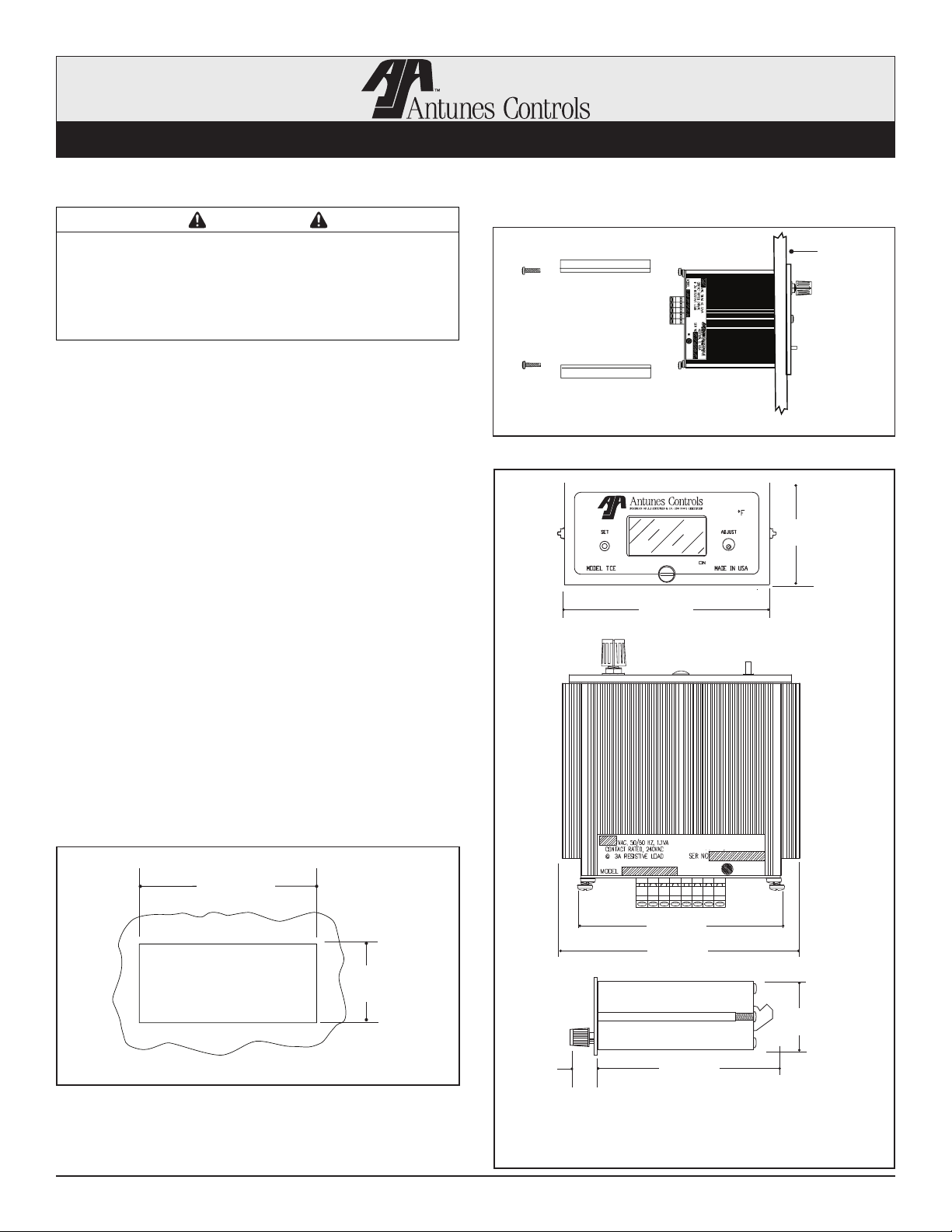
Panel Installation
Panel
Panel Locking Bars
and 6-32 Screws
Insert the unit into the panel from the front.
Secure in place with the two locking bars and
screws provided with the unit.
Dimensions
2.11”
(54 mm)
4.3”
(109 mm)
Panel Cutout
3.62”
3.57”
(91 mm)
4.27”
(108 mm)
1.77”
1.72”
(44 mm)
0.63”
(16 mm)
TCE Side View
Panel Knockout: 1.77” Ht. x 3.62” Wd. (45 mm x 92 mm)
NOTE: Dimensions are for reference only.
1-630-784-1000 Fax: 630-784-1651 Page 1 of 4 P/N 1011092 Rev. A 11/11
1-800-253-2991
4.17”
(106 mm)
Page 2
A. J. ANTUNES & CO. www.ajantunes.com 180 Kehoe Blvd., Carol Stream, Illinois 60188
TCE Installation Information
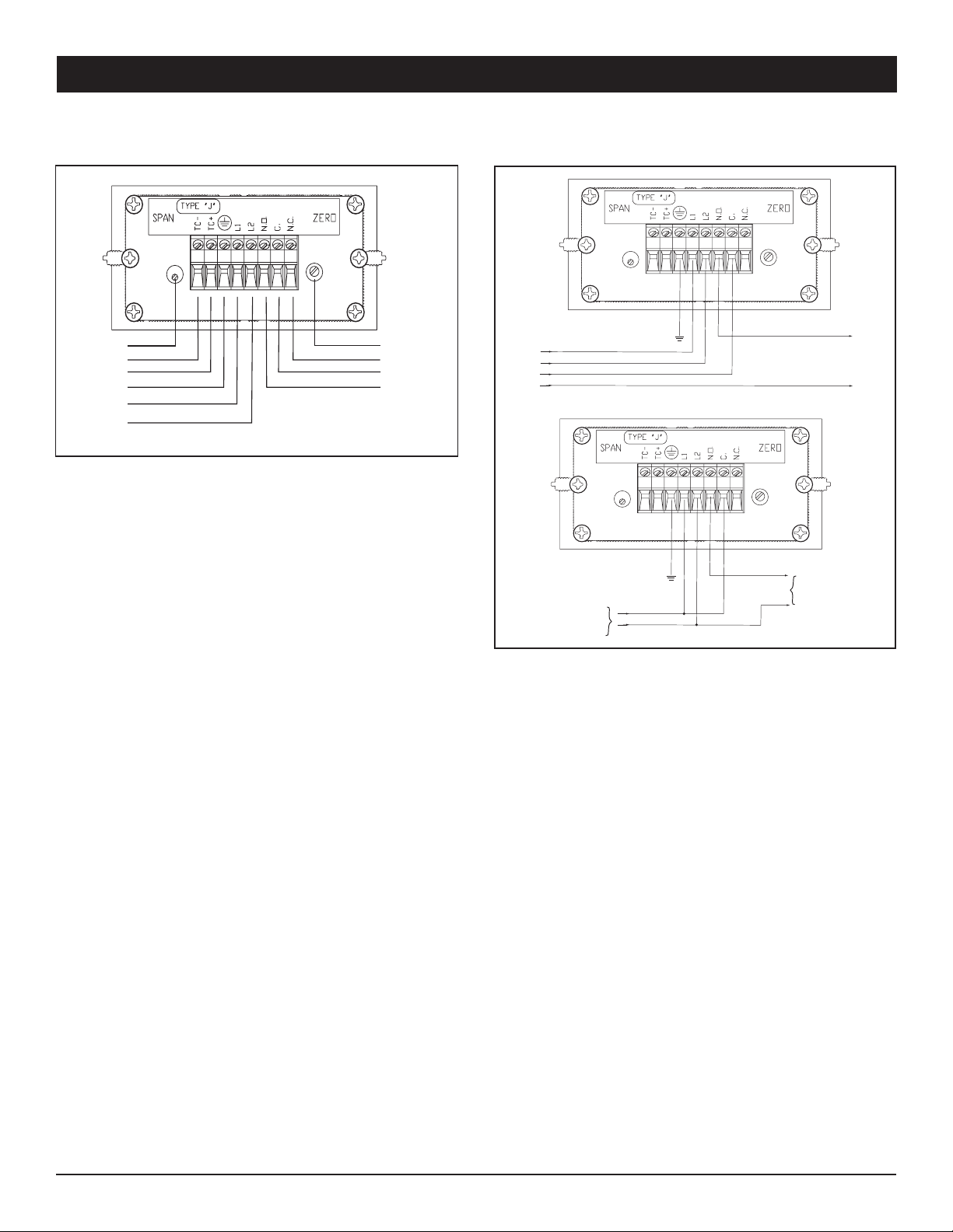
Wiring Diagram Wiring for Different Power Requirements
Span
TC-
TC+
Earth Ground
Power
Input
{
Zero
N.C.
C.
N.O.
}
Relay
Output
The wiring diagram shows connections for a Type J or K
thermocouple wire via terminals. For a long thermocouple
run, the proper thermocouple extension wire must be
used, and the proper polarity must be maintained. If
these precautions are not observed, the unit may not
meet specifications.
Power and thermocouple wire should not be placed in
the same conduit or wiring trough. However, wires from
several thermocouples may be in the same conduit or
wiring trough.
If shielded thermocouples are used, the shields should
be insulated electrically from the thermocouple wires and
terminated to earth ground.
The unit will read “EEE” for over range conditions, and
“---” for under range conditions.
Unit Power In
Control Device Power In
Unit & Control Device
Power In
112 VAC/DC
115 VAC
230 VAC
50/60Hz
To Device
Being Controlled
112 VAC/DC
115 VAC
230 VAC
50/60Hz
To Device
Being Controlled
The figure above illustrates how to wire the relays for the
different power requirements. The relay must have an
external power source for you to be able to control your
device.
If field calibration is required, a two-point calibration
with a millivolt generator can be used. Allow 30 minutes
for the unit to stabilize before calibrating. Calibrate the
low reading by adjusting the zero pot. Enter the second
calibration higher than the first point and adjust the span.
Recall these two points if needed.
1-630-784-1000 Fax: 630-784-1651 Page 2 of 4 P/N 1011092 Rev. A 11/11
1-800-253-2991
Page 3

A. J. ANTUNES & CO. www.ajantunes.com 180 Kehoe Blvd., Carol Stream, Illinois 60188
TCE Installation Information
Set Point Calibration and Output States
NC
C
NO
Temperature over
set point, relay not
operated
When the button on the lower left of the unit is pushed in
and held the set point is displayed. As long as the button
is held in the set point is displayed. When the button is
out the temperature at the thermocouple is displayed.
The knob on the lower right is used to change the set
point. Turn the knob clockwise to increase the set point.
Turn the knob counter clockwise to decrease the set
point.
The diagram above shows the output states of the
controller internal relay when the temperature, as seen by
the thermocouple, is above or below the set point. When
the relay is energized the decimal point following the least
significant digit (extreme right) will be illuminated. Make
connections accordingly, observing the power rating of
the contacts. If the thermocouple “opens” the internal
relay will go to its “not operated” state.
NC
C
NO
Temperature under set
point, relay operated
Solid State Relay Output
When the temperature seen by the thermocouple is
above the set point, there will not be any voltage between
– and + terminals (pin 8 & 6). If the temperature seen
by the thermocouple is below the set point, there will be
12-16 VDC output. This output is capable of providing
30 mA. If an “open” thermocouple condition occurs, the
voltages between pins 8 & 6 will be zero.
Warranty
1. Antunes Controls products are guaranteed to be free
from mechanical and electrical defects for a period of
one year from date of shipment under normal use and
service provided installation is made in accordance
with manufacturers’ recommendations.
2. Parts deemed defective shall be repaired or replaced
at manufacturers option and at manufacturers expense
but shall not include foreign or federal excise taxes,
state or municipal sale or use taxes, all such taxes
not limited to the foregoing being responsibility of the
purchaser.
3. No charge for travel and/or mileage will be allowed to
purchaser.
4. Antunes Controls reserves the right to make changes
in design or make any improvements on any products.
The right is always reserved to modify our equipment
because of new technology, underwriter’s requirements
and/or government regulations.
5. The following are not covered under warranty:
a. Failure from neglect, abuse, careless handling and
mis-application of unit.
b. Failure to observe guidelines for installation or
improper voltage hook-up.
c. Failure caused by improper maintenance.
d. Unless specifically allowed by Antunes Controls, no
other charges may be included under warranty.
Limitation of Liability: If it is understood and agreed
that seller’s liability whether in contract, in tort, under
any warranty, in negligence or otherwise, shall not
exceed the return of the amount of the purchase price
paid by purchaser and under no circumstances shall
seller be liable for special, indirect or consequential
damages. The price stated for the equipment is a
consideration in limiting seller’s liability. No action,
regardless of form, arising out of the transactions may
be brought by purchaser more than one year after the
cause of action has accrued.
1-630-784-1000 Fax: 630-784-1651 Page 3 of 4 P/N 1011092 Rev. A 11/11
1-800-253-2991
Page 4

 Loading...