


DVD Stereo
System
XR-DV700
U
For assistance and information
(United States and Puerto Rico)
8B-CQA-903-01 010420ACK-U-M
OPERATING INSTRUCTIONS |
En (English) |
MANUAL DE INSTRUCCIONES |
E (Español) |
MODE D'EMPLOI |
F (Français) |

PRECAUTION
Read these Operating Instructions carefully and completely before operating the unit. All precautions on this booklet and on the unit should be strictly followed.
Keep the Operating Instructions for future reference.
En WARNING
To reduce the risk of fire or electric shock, do not expose this appliance to rain or moisture.
CAUTION |
RISK OF ELECTRIC SHOCK |
DO NOT OPEN |
“CAUTION:TO REDUCE THE RISK OF |
ELECTRIC SHOCK, |
DO NOT REMOVE COVER (OR BACK). |
NO USER-SERVICEABLE PARTS INSIDE. |
REFER SERVICING TO QUALIFIED |
SERVICE PERSONNEL.” |
Explanation of Graphical Symbols:
The lightning flash with arrowhead symbol, within an equilateral triangle, is intended to alert the user to the presence of uninsulated “dangerous voltage” within the product’s enclosure that may be of sufficient magnitude to constitute a risk of electric shock to persons.
The exclamation point within an equilateral triangle is intended to alert the user to the presence of important operating and maintenance (servicing) instructions in the literature accompanying the appliance.
Warning
To prevent electric shock or injury, these safety instructions should be followed in the installation, use and servicing the unit.
Installation
Attachments — Do not use attachments not recommended by the unit manufacturer as they may result in the risk of fire, electric shock or injury to persons.
Water and Moisture — Do not use this unit near water - for example, near a bathtub, washbowl, kitchen sink, or laundry tub, in a wet basement, or near a swimming pool, and the like.
Heat — Do not use this unit near sources of heat, including heating vents, stoves, or other appliances that generate heat. It also should not be placed in temperatures less than 5˚C (41˚F) or greater than 35˚C (95˚F ).
Mounting surface — Place the unit on a flat, even surface. Accessories — Do not place this unit on an unstable cart, stand, tripod, bracket, or table. The unit may fall, causing serious injury to a child or an adult, and serious damage to the appliance. Use only with a cart, stand, tripod, bracket, or table recommended by the manufacturer, or sold with the unit. Any mounting of the appliance should follow the manufacturer’s instructions, and should use a mounting accessory recommended by the manufacturer.
Portable cart — An appliance and cart PORTABLE CART combination should be moved with care. 
 WARNING
 Quick stops, excessive force, and uneven
surfaces may cause the appliance and cart combination to overturn.
S3125A
Ventilation — The unit should be situated with adequate space around it so that proper heat ventilation is assured. Allow 15 cm clearance from the rear and the top of the unit, and 5 cm from the each side.
Slots and openings in the cabinet and the back or bottom are provided for ventilation, and to ensure reliable operation of the unit and to protect it from overheating, these openings must not be blocked or covered. The openings should never be blocked by placing the unit on a bed, sofa, rug or other similar surface. (This unit should never by placed near or over a radiator or heat register.) This unit should not be placed in a built-in installation such as a bookcase unless proper ventilation is provided.
Object and Liquid Entry — Never push objects of any kind into this unit through the cabinet slots as they may touch dangerous voltage points or short-circuit parts that could result in a fire or electric shock. Never spill liquid of any kind on the unit.
Wall or ceiling mounting — The unit should not be mounted on a wall or ceiling, unless specified in the Operating Instructions.
Electric Power
Power Sources — This unit should be operated only from the type of power source indicated on the marking label. If you are not sure of the type of power supply to your home, consult your appliance dealer or local power company. To operate unit on battery power, or other sources, refer to the operating instructions.
Grounding or Polarization — This unit is provided with a polarized alternating-current line plug (a plug having one blade wider than the other). This plug will fit into the power outlet only one way. This is a safety feature. If you are unable to insert the plug fully into the outlet, try reversing the plug. If the plug should still fail to fit, contact your electrician to replace your obsolete outlet. Do not defeat the safety purpose of the polarized plug.
Power-Cord Protection -— Power-supply cords should be routed so that they are not likely to be walked on or pinched by items placed upon or against them, paying particular attention to cords at plugs, convenience receptacles, and the point where they exit from the product.
2
Overloading — Do not allow anything to rest on the power cord. Do not overload wall outlets and extension cords as this can result in fire or electric shock. Do not locate this unit where the cord will be abused by persons walking on it.
Outdoor Antenna
Power lines — An outside antenna system should not be located in the vicinity of overhead power lines or other electric light or power circuits, or where it can fall into such power lines or circuits. When installing an outside antenna system, extreme care should be taken to keep from touching such power lines or circuits as contact with them might be fatal.
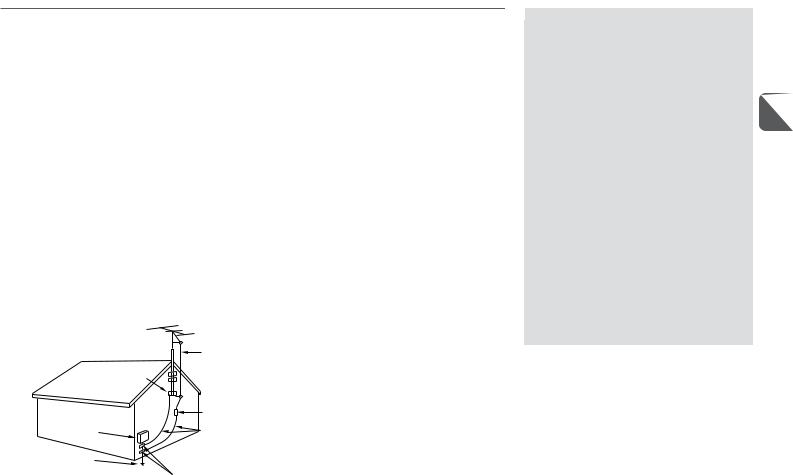
Outdoor Antenna Grounding — If an outside antenna or cable system is connected to the unit, be sure the antenna or cable system is grounded so as to provide some protection against voltage surges and built-up static charges. Section 810 of the National Electrical Code, ANSI/NFPA No.70, provides information with regard to proper grounding of the mast and supporting structure, grounding of the lead-in wire to an antenna discharge unit, size of grounding conductors, location of antenna-discharge unit, connection to grounding electrodes, and requirements for the grounding electrode. See the figure.
Antenna Grounding According |
ANTENNA |
||
to the National Electrical Code |
LEAD IN |
||
|
|
WIRE |
|
GROUND CLAMP |
ANTENNA |
||
DISCHARGE |
|||
|
|
||
|
|
UNIT |
|
ELECTRIC |
|
(NEC SECTION |
|
|
810-20) |
||
SERVICE |
|
GROUNDING |
|
EQUIPMENT |
|
||
|
|
CONDUCTORS |
|
POWER SERVICE |
|
(NEC SECTION |
|
|
810-21) |
||
GROUNDING |
|
||
|
GROUND CLAMPS |
||
ELECTRODE SYSTEM |
|
||
|
|
||
(NEC ART 250 PART H) |
NEC-NATIONAL ELECTRICAL CODE |
||
Lightning
For added protection for this unit receiver during a lightning storm, or when it is left unattended and unused for long periods of time, unplug it from the wall outlet and disconnect the antenna or cable system. This will prevent damage to the unit due to lightning and powerline surges.
Maintenance
Cleaning — Unplug this unit from the wall outlet before cleaning. Do not use liquid cleaners or aerosol cleaners. Use a damp cloth for cleaning.
Damage Requiring Service
Unplug this unit from the wall outlet and refer servicing to qualified service personnel under the following conditions: 1)When the power cord or plug is damaged or frayed.
2)If the liquid has been spilled into the unit. 3)If the unit has been exposed to rain or water.
4)If the unit does not operate normally by following the operating instructions. Adjust only those controls that are covered by the operating instructions as improper adjustment of other controls may result in damage and will often require extensive work by a qualified technician to restore the unit to normal operation.
5)If the unit has been dropped or the cabinet has been damaged.
6)When the unit exhibits a distinct change in performance - this indicates a need for service.
Do not attempt to service this unit yourself as opening or removing covers may expose you to dangerous voltage or other hazards. Refer all servicing to qualified service personnel. Replacement Parts — When replacement parts are required, be sure the service technician has used replacement parts specified by the manufacturer or having the same characteristics as the original part. Unauthorized substitutions may result in fire, electric shock or other hazards.
Safety Check — Upon the completion of any service or repairs to this unit, ask the service technician to perform safety checks to determine that the unit is in proper operating condition.
TABLE OF CONTENTS |
|
PRECAUTION ...................................... |
2 |
PREPARATION .................................... |
5 |
PARTS AND CONTROLS ......................... |
8 |
ADJUSTMENT BEFORE OPERATION ......... |
12 |
PLAYING DISCS |
|
|
En |
PREPARATORY INFORMATION ......... |
14 |
BASIC PLAYBACK ........................ |
15 |
SELECTING TRACKS/CHAPTERS ....... |
17 |
OTHER PLAYBACK MODES .................. |
18 |
DVD FEATURES ........................... |
20 |
STATUS DISPLAY ......................... |
22 |
DOLBY AND DTS SURROUND ................ |
23 |
RADIO ............................................ |
25 |
SOUND ........................................... |
27 |
TIMER ............................................ |
28 |
EXTERNAL EQUIPMENT ....................... |
30 |
CUSTOMIZING DVD SETUP ................... |
31 |
REFERENCE ..................................... |
38 |
3

|
OWNER'S RECORD |
||
|
Record the model number and serial number of your set |
||
|
(found at the rear of your set) below. Refer to them when |
||
|
contacting your Aiwa dealer. |
||
|
Model No. _____________________________ |
||
En |
Serial No. _____________________________ |
||
|
|
|
|
|
|
|
|
System and accessories
XR-DV700
CX-LDV700 DVD stereo system
SX-L700 Five Surround speaker system (front speakers, surround speakers, center speaker)
TS-LW700 Subwoofer Remote control
Lithium battery (CR2025) FM antenna, AM antenna Connecting cord (DIN 8-pin) Video connecting cord
Front speakers cord (approx. 4 m / 13 ft.) × 2
Surround speaker cord (with plugs, approx. 8 m / 26 ft.) × 2 The red plug is for the right channel and the white plug is for the left channel.
Center speaker cord (with an orange plug, approx. 3 m / 10 ft.) × 1
Pedestal × 2
4

PREPARATION
Placement |
To attach the front speaker to the pedestal |
Placing the main unit |
|
|
Allow 15 cm (6 in.) clearance from the top of the unit for |
|
|
Place the speakers in their proper position. All speakers for a |
|
|
|
|
movement of the disc compartment lid. |
|
|
full 5.1-channel home theater come supplied with your DVD |
|
|
|
|
Attaching the anti-skid patches |
|
|
system. |
|
|
|
|
|
To prevent the surround and center speakers from slipping, |
|
|
|
attach the supplied anti-skid patches to the bottom of the |
|
|
|
speakers. Use 3 patches for each of these speakers. |
En |
|
|
|
|
|
To mount the surround speakers on the wall |
|
|
|
Mount each speaker on a spot that can hold its weight. |
|
|
L&R: Front speakers (marked "FRONT") C: Center speaker (marked "CENTER")
Place it in the center of the two front speakers, possibly on or below the TV set.
LS&RS: Surround speakers (marked "REAR")
Place them directly to the side of or slightly behind the listening area. Align them horizontally, preferably about 1 meter (3 feet) above ear height.
SW: Subwoofer
Place it on the floor close to a wall or in a corner of the room.
AIWA disclaims any responsibility for injury to persons or other accidents caused by not fitting the surround speakers properly or if the place of the installation is not suitable.
•Either of the two front speakers can be used as the right or the left one; likewise for the surround speakers.
•Do not place the left and right front speakers close to the TV set, as doing so may cause picture noise.
•Sound output from the center and the surround speakers is only available when the Dolby or the DTS surround system is activated with the appropriate setting.
5

Connection
Plug in the AC power cord to the AC power outlet after all other connections are made.
En
Center speaker |
Surround speaker |
TV set
Surround speaker
Front |
Front |
speaker |
speaker |
6
1Connect the bare ends of each speaker cord to the corresponding speaker.
Be sure to use the correct cord for each speaker.
-Front speaker cords have bare leads at both ends (approx. 4 m / 13 ft.).
-Surround speaker cords are the longer cords with a plug at one end (approx. 8 m / 26 ft.).
The red plug is for the right channel and the white plug is for the left channel.
-Center speaker cord is the short cord with an orange plug at one end (approx. 3 m / 10 ft.).
The copper-colored cords go to the 0terminal of each speaker.
2Connect the cords from the front speakers to the appropriate terminals on the subwoofer.
-Right front speaker: FRONT R terminals
-Left front speaker: FRONT L terminals
The copper-colored cords go to the 0terminals.
3Connect the cords from the surround speakers to the appropriate jacks on the subwoofer.
-Right surround speaker: SURROUND R jack (red)
-Left surround speaker: SURROUND L jack (white)
4Connect the cord from the center speaker to the CENTER jack (orange) on the subwoofer.
5Connect the subwoofer to the main unit.
Connect the FROM CX-LDV700U jack of the subwoofer to the TO TS-LW700U jack with the supplied connecting cord (DIN 8-pin).
•Do not connect other equipment to the TO TS-LW700U jack because this is used exclusively for the supplied subwoofer.
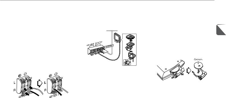
6Connect the supplied antennas.
Connect the FM antenna to the FM 75 Ω terminals and the AM antenna to the AM LOOP terminals.
FM antenna
AM antenna
7Connect the television set.
If your TV set has an S-video input jack:
Connect the S-VIDEO OUT (S1) jack of this unit and the S-video input jack of your TV with an optional S-video connecting cord.
If your TV set does not have an S-video input jack: Connect the VIDEO OUT jack of this unit and the video input jack of your TV with the supplied video connecting cord (the one with plugs at both ends).
Refer also to the Operating Instructions of your TV set. The illustration shows the connection to the VIDEO OUT jack.
•If your TV set is a wide-screen set: you need to adjust the TV aspect setting later (see “TV Aspect”, page 33).
•Do not use more than one connection to connect your TV.
8Connect the power supply.
Plug in the AC power cords of the main unit and the subwoofer to AC outlets.
The automatic demonstration will run on the display while the power is turned off.
To deactivate the automatic demonstration, press DEMO/ ECO. The clock will flash on the display. For setting the clock, see page 13.
•Do not short-circuit the 0and 9speaker cord leads. |
|
•Do not leave objects generating magnetism or objects |
En |
affected by magnetism near the speakers. |
Remote control
While sliding the latch, pull out the battery holder from the bottom of the remote control. Place the supplied battery on the battery holder with correct polarity. Finally, insert the holder back into position.
•Replace the battery with a new one when the operational distance between the remote control and main unit becomes shorter.
•Remove the battery if the unit is not going to be used for an extended period of time.
•The remote control may not operate if it is used under intense sunlight or if its line of sight is obstructed.
Caution!
•Do not keep the battery near metallic objects such as rings, bracelets, and keys. It may cause the battery to short circuit.
•After removing the battery, be sure to keep it out of reach of children. In case it is swallowed, consult a doctor immediately.
7
PARTS AND CONTROLS
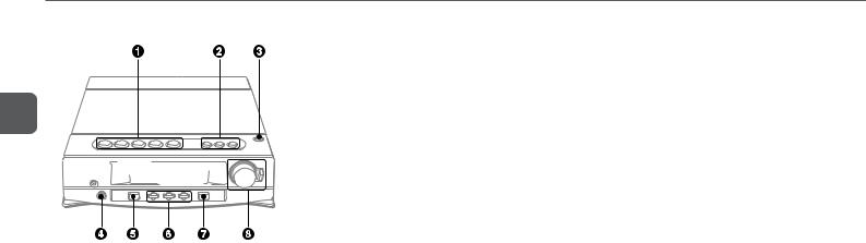
Main unit: front
En |
2TUNER/BAND
Selects radio function and the radio band.
AUX
Selects AUX function.
DVD/CD
Selects DVD/CD function.
3zOPEN/CLOSE
Opens and closes the disc compartment.
4PHONES jack
8VOLUME/MULTI JOG
Adjusts the volume.
Changes the menu item selection in the MODE setting.
MODE
Adjusts various mode and sound settings. Press repeatedly to select among T-BASS, BASS, TREBLE, SLEEP and TIMER.
ENTER
Enters the item selected with MULTI JOG.
|
Plug in here an optional headphones set with a stereo |
|
|
mini plug (ø3.5 mm, 1/8 in.). Speaker output is canceled. |
|
|
5 POWER 6STANDBY/ON |
|
1 aSET |
Switches the unit on and off (standby). |
|
|
||
Disc: pauses playback. |
6 DEMO/ECO |
|
Radio: stores the received station to preset. |
When the unit is turned off: selects ECO mode, DEMO |
|
sCLEAR |
mode or displays the clock. |
|
When the unit is turned on: selects DEMO mode. |
||
Disc: stops playback. |
||
|
||
Radio: clears a station preset. |
DISPLAY |
|
cPRESET |
Disc: displays the title/chapter/track number being played |
|
and remaining time of play. |
||
Disc: starts playback. |
||
Radio: displays the frequency of the tuned station. |
||
Radio: tunes into a preset station. |
||
|
||
frDOWN, gtUP |
COLOR |
|
Selects the display color. |
||
Disc: skips to a previous or a succeeding chapter/track |
||
|
||
when pressed, searches a title/track in fast forward or |
7 SURROUND |
|
fast reverse playback when held down. |
Turns on the Dolby or DTS decoder. Press repeatedly to |
|
Radio: manually tunes down or up within the band. |
select a listening mode. |
8

Main unit: rear |
Subwoofer |
1VIDEO OUT jack
Outputs standard (composite) video signals.
S-VIDEO OUT (S1) jack
Outputs S-VIDEO signals.
DIGITAL OUT (OPTICAL) jack
Outputs digital audio signals to external digital equipment. Keep the jack covered with the supplied dust cap when it is not being used.
CAUTION
NEVER play a multichannel Dolby Digital or a DTS source through external digital equipment without a Dolby Digital or a DTS decoder, respectively. Doing so will generate high level noise which may be harmful to your ears and damage the speakers.
2AM LOOP, FM 75 Ω terminals
Plug in the supplied AM and FM antennas here.
3TO TS-LW700U jack
Connect the supplied powered subwoofer here.
4AC power cord
5LINE OUT jacks
Outputs analog sound signals to external equipment.
6AUX jacks
Accepts analog sound signals from external equipment.
En
7FRONT 3terminals
Connect the supplied front speakers here.
8CENTER 3jack (orange)
Connect the center speaker here.
SURROUND 3jacks (red or white)
Connect the surround speakers here.
9FROM CX-LDV700U jack
Connect the main unit here with the supplied connecting cord (DIN 8-pin).
0 AC power cord
9

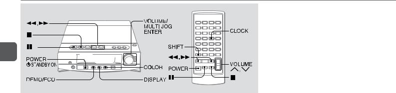
Remote control
En
Buttons with same or similar names with the main unit basically have the same function.
10-9, +10
Disc: selects a title/chapter/track of the specified number. Selects a menu item for VCDs with PBC.
Radio: tunes in to the station with the specified preset number.
SUB TITLE ON/OFF
Switches the subtitle on and off (DVDs only).
T-SEARCH
Enters the time search mode to locate a point in the disc by specifying the title number, chapter number or the playback time (DVDs only).
MARK
Enters the Mark mode to mark a point in the disc or to start playback from a marked point (DVDs only).
ANGLE
Selects the angle to view the scene (DVDs only).
REPEAT
Enters repeat playback mode.
RANDOM/PRGM
Enters random or programmed playback mode (CDs and VCDs).
PBC
Switches PBC(Playback Control) on and off for VCDs.
TIMER
Enters timer setting mode.
SLEEP
C |
Enters sleep-timer setting mode. |
|
Clears the Mark memory, etc. |
CLOCK |
|
2 The numbered buttons take on these functions when pressed |
||
Enters clock adjustment mode. |
||
together with SHIFT: |
3 T-BASS |
|
|
||
AUDIO SELECT |
Emphasizes low frequency sound. |
|
Changes audio tracks (DVDs) or channels (VCDs). |
TITLE |
|
|
||
SUB TITLE SELECT |
Displays the title menu for DVDs. |
|
Changes the subtitle language (DVDs only). |
|
vVBb
Changes the menu item selection.
ENTER
Enter the selected item.
MENU
Displays the menu for DVDs.
SETUP
During stop: enters the setup menu.
During playback: changes the playback time display of a disc.
SURROUND
RETURN
Returns to the previous menu screen. Displays the menu for VCDs.
SHIFT
Hold down when pressing a numbered button to change its function to that printed above the number.
•e.g., "Press SHIFT+TIMER on the remote control" means to hold down SHIFT and press 0/TIMER to use the button for the timer function.
4The following buttons take on these functions when pressed together with SHIFT:
MONO TUNER
Switches between stereo or monaural FM reception.
ZOOM
Enlarge the picture (DVDs only).
10
CENTER(+, -)
Adjusts the sound level of the center speaker for Dolby and DTS surround.
REAR(+, -)
Adjusts the sound level of the surround speakers for Dolby and DTS surround.
MAN/SEL (Manual/Select)
Enters speaker level and delay time setting mode.
5f/rDOWN cPRESET g/tUP aSET sCLEAR
6POWER
7TUNER BAND AUX
DVD/CD
ON SCREEN DISPLAY
Displays disc playback status on the TV screen.
8VOLUME (N,M)
Display window
7 T-BASS level indicators
Displays the T-BASS level.
8
9 |
0 |
Disc type indicators
Indicates the type of current disc (CD or VCD).
Track/preset number indicator |
En |
Displays the track number of CD or VCD and preset |
|
number of radio. The current track/preset number flashes. |
|
Output type indicators |
|
1Disc indicators
Rotates during playback. Lights up during stop. "DISC" lights up while the disc is loaded.
2Audio signal type indicators
Indicates the signal type of the current audio track.
3Main display
The surround playback mode indicators ("DOWNMIX" and "hPRO LOGIC") indicate the surround output type in which the source is actually being played.
The "OVER" level indicator lights up when external input level from the AUX jacks is too high.
!MONO/1(stereo) indicators
Indicates the type of radio reception.
@SLEEP indicator
Lights up when the sleep function is active.
Shows general information such as the active function, current adjustment mode, title/chapter/track number, elapsed time, radio frequency, or the time.
45indicator
Lights up when the timer function is active.
5Playback mode indicators
Lights up to show the programmed, repeat, and random playback modes.
6KARAOKE indicator
Lights up when playing Dolby Digital karaoke disc.
11
ADJUSTMENTS BEFORE OPERATION
En
When power economizing mode is activated
When the unit turns off, "ECO MODE" is displayed for 4 seconds, and everything on the display clears.
Only the red indicator on the POWER button lights to show that power is being supplied to the unit.
Standby power consumption
When power economizing mode is activated: 0.7 W When power economizing mode is deactivated: 9 W
Power
Press POWER 6STANDBY/ON (POWER on the remote control) to turn the unit on and off.
Volume
Turn VOLUME/MULTI JOG, or press VOLUME N,Mon the remote control.
Adjust from 0 (minimum) to 30 and MAX (maximum).
•Volume level setting is retained during power-off standby. If the unit is turned off with the volume set to 21 or more, it is automatically turned down to 20 the next time the unit is turned on.
DEMO
If the clock has not been set, "DEMO" appears on the display when the unit is turned off.
To deactivate the DEMO
While "DEMO" is displayed, press DEMO/ECO. The clock flashes. For setting the clock, see page 13.
ECO mode
Reduces power consumption with the following operations.
After clock is set, this unit allows you to regulate its power consumption by displaying nothing on the display while the power is off. This is called power economizing mode.
Press DEMO/ECO while the unit is turned off.
Each press of this button changes the display status as follows:
1Demo display (power economizing mode canceled)
2Power economizing mode
3Clock display (power economizing mode canceled) Pressing a or ENTER turns on the backlight for 4 seconds.
12
 Loading...