


D33 English
SERVICE MANUAL
VIDEO MECHANISM
TYPE
P2 LRN106A
P4 LRN133A
S/M Code No. 09-99B-336-8N2
DATA
TABLE OF CONTENTS
REMOVING CASSETTE MANUALLY ............................. |
3 |
|
DECK MECHANISM PARTS LOCATIONS |
|
|
Top View ............................................................................ |
4 |
|
Bottom View ...................................................................... |
4 |
|
DECK MECHANISM DISASSEMBLY |
|
|
1. |
Drum Assembly ........................................................... |
5 |
2. |
Plate Assembly Top ..................................................... |
7 |
3. |
Holder Assembly CST ................................................. |
7 |
4. |
Guide CST .................................................................. |
7 |
5. |
Bracket Side (L)/Bracket Assembly Door .................... |
7 |
6. Arm Assembly F/L ....................................................... |
7 |
|
7. |
Lever Assembly S/W ................................................... |
7 |
8. Arm Assembly Cleaner ................................................ |
8 |
|
9. |
Head F/E ..................................................................... |
8 |
10. |
Base Assembly A/C Head ........................................... |
8 |
11. Brake Assembly S ....................................................... |
9 |
|
12. |
Brake Assembly T ....................................................... |
9 |
13. Arm Assembly Tension ................................................ |
9 |
|
14. |
Reel S & Reel T .......................................................... |
9 |
15. |
Support CST ............................................................. |
10 |
16. |
Base Assembly P4 .................................................... |
10 |
17. |
Opener Lid ................................................................ |
10 |
18. Arm Assembly T/up ................................................... |
10 |
|
19. Arm Assembly Pinch ................................................. |
10 |
|
20. |
Belt Capstan/Motor Capstan ..................................... |
11 |
21.Clutch Assembly D33 ................................................. |
11 |
|
22. |
Lever F/R .................................................................. |
11 |
23. |
Gear Assembly H-Up/D or Gear Assembly Up/D ...... |
11 |
24. |
Bracket Assembly Jog ............................................... |
12 |
25. |
Guide Rack F/L, Gear Rack F/L ................................ |
12 |
26. |
Brake Assembly Capstan .......................................... |
12 |
27. |
Gear Drive/Gear Cam/Gear Connector .................... |
13 |
28. |
Bracket Assembly L/D motor ..................................... |
13 |
29. |
Gear Sector ............................................................... |
14 |
30. |
Base Tension/Plate Slider/Lever Tension .................. |
14 |
31. |
Gear Assembly P3/Gear Assembly P2 ..................... |
15 |
32. |
Base Assembly P3/Base Assembly P2 ..................... |
15 |
33. Arm Assembly Idler Jog or Arm assembly Idler ......... |
15 |
|
DECK MECHANISM ADJUSTMENT |
|
|
Tools and Fixtures for service ......................................... |
16 |
|
1. |
Mechanism Alignment Position Check ........................ |
17 |
2. |
Preparation for Adjustment ......................................... |
18 |
3. |
Checking Torque ......................................................... |
18 |
4. |
Guide Roller Height Adjustment .................................. |
19 |
4-1. Preliminary Adjustment .......................................... |
19 |
|
4-2. Precise Adjustment ................................................ |
19 |
|
5. Audio/Control (A/C) Head Adjustment ......................... |
20 |
|
5-1. Preliminary Adjustment .......................................... |
20 |
|
5-2. Confirm that the Tape Path smoothly between |
|
|
|
the Take-up Guide and Pinch Roller ..................... |
21 |
5-3. Precise Adjustment (Azimuth Adjustment) ............. |
21 |
|
6. |
X-Value Adjustment ..................................................... |
21 |
7. Adjustment after Replacing Drum Assembly |
|
|
|
(Video Heads) ............................................................. |
22 |
8. |
Check the Tape Travel after Reassembling |
|
|
Deck Mechanism......................................................... |
22 |
8-1. Checking Audio and RF Locking Time |
|
|
|
during Playback and after CUE or REV ................ |
22 |
8-2. Check for Tape Curling or Jamming ....................... |
22 |
|
MAINTENANCE/INSPECTION PROCEDURE |
|
|
1. |
Check before starting Repairs .................................... |
23 |
2. |
Required Maintenance ................................................ |
24 |
3. |
Scheduled Maintenance ............................................. |
24 |
4. |
Supplies Required for Inspection and Maintenance ... |
24 |
5. |
Maintenance Procedure .............................................. |
24 |
5-1. Cleaning ................................................................. |
24 |
|
5-2. Greasing ................................................................ |
25 |
|
MECHANISM TROUBLESHOOTING GUIDE |
|
|
1. |
Deck Mechanism ........................................................ |
26 |
2. |
Front Loading Mechanism .......................................... |
29 |
MECHANISM EXPLODED VIEW 1/3 ............................. |
32 |
|
MECHANISM MAIN PARTS LIST 1/3 ............................ |
33 |
|
MECHANISM EXPLODED VIEW 2/3 ............................. |
34 |
|
MECHANISM MAIN PARTS LIST 2/3 ............................ |
35 |
|
MECHANISM EXPLODED VIEW 3/3 ............................. |
36 |
|
MECHANISM MAIN PARTS LIST 3/3 ............................ |
37 |
|
2
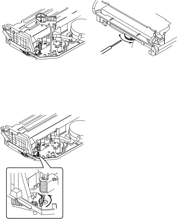
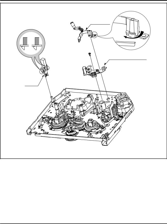
REMOVING CASSETTE MANUALLY
1. Remove the loading motor.
3. Turn the capstan belt to take up slack tape.
Loading motor
Capstan belt
Fine rod, etc.
Fig. 1 |
Fig. 3 |
2.Turn the gear connect in the direction of the arrow with you finger to perform unsledding.
4.Turn the gear connect in the direction of the arrow with you finger to perform unloading.
Gear connect
Fig. 2
3
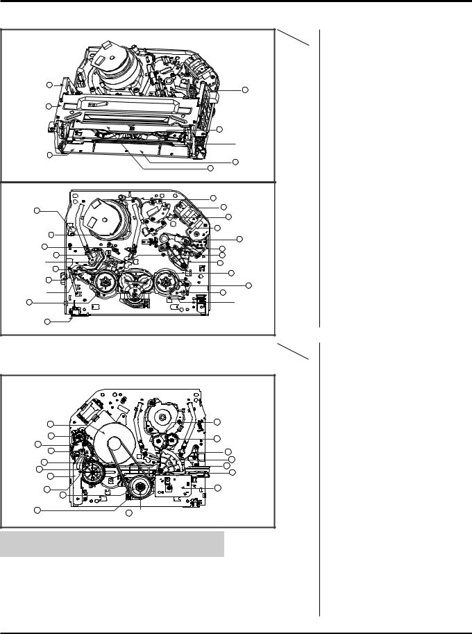
DECK MECHANISM PARTS LOCATIONS
• Top View
Bracket Side 'L' 5 |
6 Bracket |
|
|
||
|
Assembly Door |
|
Plate Assembly 2 |
|
|
Top |
|
|
|
7 Arm Assembly F/L |
|
|
Opener Door |
|
Lever Assembly 8 |
|
|
S/W |
4 Guide CST |
|
|
3 Holder Assembly CST |
|
|
9 Arm Assembly Cleaner |
|
Head F/E 10 |
34 Bracket Assembly |
|
L/D Motor |
||
|
11 Base Assembly |
|
|
A/C Head |
|
|
21 Arm Assembly Pinch |
|
Drum Assembly 1 |
19 Opener Lid |
|
|
||
Support CST 17 |
18 Base Assembly P4 |
|
|
||
Base Assembly P2 42 |
41 Base Assembly P3 |
|
Brake Spring S |
20 Arm Assembly T/Up |
|
Brake Assembly S 12 |
43 Arm Assembly |
|
|
||
Arm Assembly 14 |
ldler Jog |
|
|
||
Tension |
16 Reel T |
|
Band Assembly |
13 Brake Assembly T |
|
Tension |
||
|
||
Reel S 15 |
Brake Spring T |
|
Lever |
|
|
Assembly S/W 8 |
|
Pracedure |
Part |
Fixing Type |
Fig- |
|
Starting |
|
|||
|
ure |
|||
No. |
|
|
|
|
|
|
|
|
|
|
1 |
Drum Assembly |
3 Screws , Cap FPC |
A-1 |
|
2 |
Plate Assembly Top |
Two Hooks |
A-2 |
2 |
3 |
Holder Assembly CST |
Chassis Hole |
A-2 |
|
4 |
Guide CST |
2 Hooks |
A-2 |
2,3,4 |
5 |
Bracket Side (L) |
1 Screw |
A-2 |
2,3,4 |
6 |
Bracket Assembly Door |
1 Screw |
A-2 |
2,3,4,5,6 |
7 |
Arm Assembly F/L |
Chassis Hole |
A-2 |
2,3,4,5 |
8 |
Lever Assembly S/W |
Chassis Hole |
A-2 |
|
9 |
Arm Assembly Cleaner |
Chassis Embossing |
A-3 |
|
10 |
Head F/E |
2 Hooks |
A-3 |
|
11 |
Base Assembly A/C Head |
1 Screw |
A-3 |
|
12 |
Brake Assembly S |
Chassis Hole |
A-4 |
2,3 |
13 |
Brake Assembly T |
Chassis Hole |
A-4 |
2,3,12, |
14 |
Arm Assembly Tension |
Chassis Hole |
A-4 |
2,3,12,14 |
15 |
Reel S |
Chassis Shaft |
A-4 |
2,3,13 |
16 |
Reel T |
Chassis Shaft |
A-4 |
|
17 |
Support CST |
Chassis Embossing |
A-5 |
|
18 |
Base Assembly P4 |
Chassis Embossing |
A-5 |
|
19 |
Opener Lid |
Chassis Embossing |
A-5 |
19 |
20 |
Arm Assembly T/Up |
Chassis Embossing |
A-5 |
19 |
21 |
Arm Assembly Pinch |
Chassis Shaft |
A-5 |
|
|
|
|
|
• Bottom View
Motor Capstan 23 |
39 Gear Assembly P3 |
|
|
||
Gear Connector 33 |
40 Gear Assembly P2 |
|
|
||
Gear Cam 32 |
|
|
Brake Assembly 30 |
36 Base Tension |
|
Capstan |
||
35 Gear Sector |
||
Belt Capstan 22 |
||
38 Lever Tension |
||
Gear Drive 31 |
||
37 Plate Slider |
||
Guide Rack F/L 28 |
||
|
||
Gear Rack F/L 29 |
27 Bracket Assembly |
|
Jog |
||
Clutch Assembly D33 24 |
||
|
||
Lever F/R 25 |
26 Gear Assembly H-Up/D |
|
|
NOTE : When reassembly perform the procedure in the reverse order.
1)When reassembling, confirm Mechanism and Mode Switch Alignment Position (Pefer to Page 17)
2)When disassembling, the Parts for Starting No. Should be removed first.
Pracedure |
Part |
Fixing Type |
Fig- |
|
Starting |
|
|||
|
ure |
|||
No. |
|
|
|
|
|
|
|
|
|
|
22 |
Belt Capstan |
|
A-6 |
22 |
23 |
Motor Capstan |
3 Screws |
A-6 |
|
24 |
ClutchAssembly D33 |
1 Washer |
A-6 |
22,24 |
25 |
Lever F/R |
1 Hook |
A-6 |
22,24 |
26 |
GearAssembly H-Up/D |
2 Washers |
A-6 |
|
27 |
BracketAssembly Jog |
1 Screw |
A-7 |
|
28 |
Guide Rack F/L |
1Screw |
A-7 |
28 |
29 |
Gear Rack F/L |
|
A-7 |
28, 29 |
30 |
BrakeAssembly Capstan |
Chassis Shaft |
A-7 |
28, 29 |
31 |
Gear Drive |
1 Washer |
A-8 |
28, 29, 30 |
32 |
Gear Cam |
Chassis Shaft |
A-8 |
28,29,30,31 |
33 |
Gear Connector |
Chassis Shaft |
A-8 |
|
34 |
BracketAssembly L/D Motor |
3 Hooks |
A-8 |
|
35 |
Gear Sector |
3 Washers |
A-9 |
|
36 |
BaseTension |
1 Screw |
A-9 |
22,24,25,27 |
37 |
Plate Slider |
Chassis Shaft |
A-9 |
28,29,31,35 |
|
|
|
|
36 |
|
|
|
|
22,24,25,27 |
|
|
|
|
28,29,31,35 |
38 |
LeverTension |
Chassis Hole |
A-9 |
36 |
|
|
|
|
35 |
39 |
GearAssembly P3 |
2 Hooks |
A-10 |
35, 39 |
40 |
GearAssembly P2 |
2 Hooks |
A-10 |
35, 39, 40 |
41 |
BaseAssembly P3 |
Chassis Hole |
A-10 |
35,39,40,41 |
42 |
BaseAssembly P2 |
Chassis Hole |
A-10 |
1, 2 |
43 |
ArmAssembly Idler Jog |
1 Hook |
A-10 |
|
|
|
|
|
4
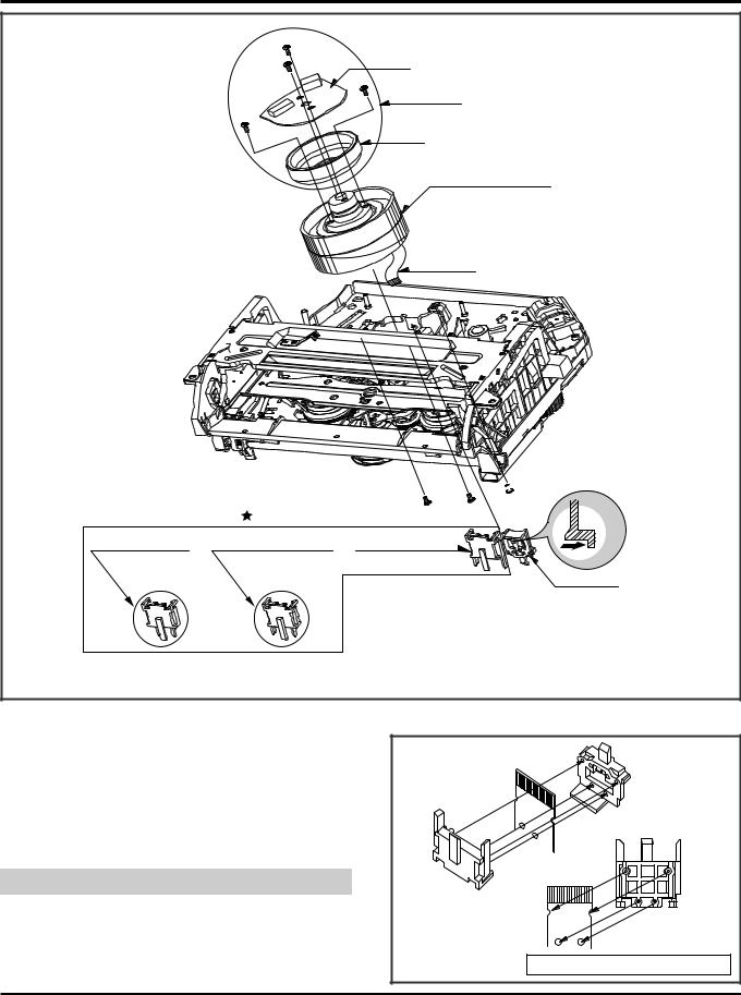
DECK MECHANISM DISASSEMBLY
(S2) |
|
(S2) |
Stator |
|
(S3) |
Drum Motor
(S3)
Rotor
Drum Sub Assembly
(Fig. A-1-1)
Drum FPC
 (S1)
(S1)
|
Optional Parts |
(S1) |
(S1) |
Holder FPC or |
Holder FPC |
or Holder FPC |
|
(only for 2HD Models) |
(only for 4HD-Mono Models) |
(only for 4HD-Hi-Fi Models) |
|
(Fig. A-1-1)
H1
Cap FPC
Fig. A-1
1. Drum Assembly (Fig. A-1-1)
1)Unhook the (H1) on the back side of the Chassis and separate the Cap FPC.
2)Remove three Screws (S1) and lift up the Drum Assembly.
3)Remove two Screws (S2) and Separate the Stator of Drum Motor.
4)Remove two Screws (S3) and Separate the Rotor of Drum Motor from the Drum Sub Assembly.
NOTE
(1)When reassembling Cap FPC, two Holes of Drum FPC are inserted to the two Bosses of Holder FPC correctly. (Refer to Fig. B-1)
(Fig. B-1) |
Cap FPC |
Drum FPC |
Holder FPC |
Figure in the opposite direction |
5

DECK MECHANISM DISASSEMBLY
H1 |
|
|
|
|
|
Plate Assembly Top |
H2 |
|
(A) |
|
|
|
|
|
|
|
|
|
(B) |
|
|
(Fig. A-2-1) |
|
|
|
Lever Stopper (L) |
Holder Assembly CST |
|
|
|
Lever Stopper (R) |
|
|
(Fig. A-2-2) |
|
|
|
Arm Assembly F/L |
|
|
|
(Fig. A-2-6) |
Arm F/L |
|
|
Lever Assembly S/W |
(S2) |
|
|
|
|
|
(H5) |
(Fig. A-2-7) |
|
Bracket Side (L) |
(S1) |
|
|
(Fig. A-2-4) |
|
|
|
|
|
Groove |
|
|
|
Gear Rack F/L Groove |
|
|
|
Guide CST |
(Fig. A-2-5) |
|
|
|
|
|
|
(Fig. A-2-3) |
Bracket |
|
|
Assembly Door |
|
H3 |
|
|
|
|
|
|
|
|
|
Fig. A-2 |
H4 |
|
|
|
|
|
|
6 |
|
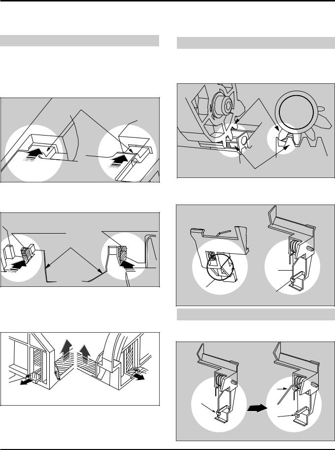
DECK MECHANISM DISASSEMBLY
2. Plate Assembly Top (Fig. A-2-1)
1)Unhook the (H1) and separate the Left Side.
2)Unhook the (H2) and lift up the Plate Assembly Top.
NOTE
(1)When reassembling, confirm (A),(B) Part of the Plate Assembly Top is inserted to the (L),(R) Grooves of the Bracket Side(L) and Bracket Assembly Door.
3. Holder Assembly CST (Fig.A-2-2)
1)Push the Lever Stopper(L),(R) in the direction of the arrows (A), (B), and move the Holder Assembly CST.
|
Plate Assembly Top |
Bracket Side (L) |
Bracket Assembly Door |
2)Push the Bracket Assembly Door to the right and lift up the Holder Assembly CST along the Guide Groove of the Bracket Assembly Door.
|
Lever Stopper (L) |
Lever Stopper (R) |
|
|
|
|
Holder Assembly CST |
|
(A) |
|
(B) |
4. Guide CST (Fig.A-2-3)
1)Push two Hooks(H3),(H4) in the direction of the arrow and separate the left side.
2)Unhook (H5),(H6) as above No.1) and disassemble the Guide CST in the direction of the arrow.
|
(H4) |
(H3) |
|
Bracket Side (L) |
Bracket Assembly Door |
5. Bracket Side(L) (Fig. A-2-4)/ |
|
Bracket Assembly Door (Fig.A-2-5) |
|
1)Remove the Screw (S1) and disassemble the Bracket Side(L) in the front.
2)Remove the Screw (S2) and disassemble the Bracket Assembly Door in the front.
6. Arm Assembly F/L (Fig. A-2-6)
1) Push the Arm Assembly F/L to the left and lift up it.
NOTE
(1)When reassembling, confirm that the Gear(A) of the Arm F/L and the Gear(B) of the Gear Rack F/L are assembled as below.
7. Lever Assembly S/W (Fig. A-2-7) |
Gear (A) |
Gear (B) |
1)Hook the Spring Lever S/W on (H5).
2)Lift up the left side of the Lever S/W from the Groove(A) of the Chassis.
Spring
Lever S/W
(H5)
(H5)
NOTE
(1)Place the Spring Lever S/W of the above (No.1) as original position.
Spring
Lever S/W
(H5)
(H5)
7
DECK MECHANISM DISASSEMBLY
|
|
Arm Assembly |
|
|
Cleaner |
|
|
(A) |
|
|
(Fig. A-3-1) |
|
|
(S1) |
|
|
Base Assembly A/C Head |
|
(Fig. A-3-2) |
(Fig. A-3-3) |
(H1) |
|
|
|
|
|
Head F/E |
|
|
|
|
Fig. A-3 |
8. Arm Assembly Cleaner(Fig. A-3-1) |
9. Head F/E (Fig. A-3-2) |
|
1)Break away the (A) part shown above Fig. A-3-1 from the Embossing of the Chassis in the clockwise direction and lift up the Arm Assembly Cleaner.
1)Unhook the two Hooks (H1) on the back side of the Chassis and lift up the Head F/E.
10. Base Assembly A/C Head (Fig. A-3-3)
1)Remove the Screw (S1) and lift up the Base Assembly A/C Head.
8
DECK MECHANISM DISASSEMBLY
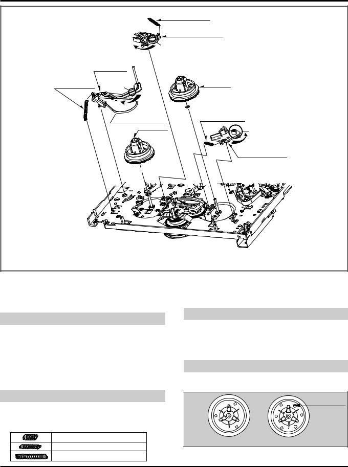
Spring S Brake
Brake Assembly S
(Fig. A-4-1)
(A)
Arm Assembly
Tension
Spring Tension |
(C) |
Reel T |
(Fig. A-4-5)
Band
(Fig. A-4-3)  Assembly Spring T Brake
Tension
Reel S
B
Brake Assembly T
(Fig. A-4-2)
 (Fig. A-4-4)
Fig. A-4
11. Brake Assembly S (Fig. A-4-1)
1)Remove the Spring S Brake.
2)Hold the (A) part shown above Fig. A-4-1 and turn to the clockwise direction, and then lift up the Brake Assembly S.
NOTE
(1)When reassembling, be careful not to change the Spring with below No.12.(Refer to Fig. B-2).
12. Brake Assembly T (Fig. A-4-2)
1)Remove the Spring T Brake.
2)Hold the (B) part shown above Fig. A-4-2 and turn to the counterclockwise direction, and then lift up the Brake Assembly T.
NOTE
(1) When reassembling, be careful not to change the Spring with above No.11.(Refer to Fig. B-2).
(Difference for Springs) |
(Fig. B-2) |
Spring T Brake Color (Black)
Spring S Brake
Spring Tension
13. Arm Assembly Tension (Fig. A-4-3)
1)Remove the Spring Tension.
2)Hold the (C) part shown above Fig. A-4-3 and turn to the clockwise direction, and then lift up the Arm Assembly Tension.
NOTE
(1)When reassembling, be careful not to change the Spring with above No.11,12.(Refer to Fig. B-2).
14. Reel S (Fig. A-4-4) & Reel T (Fig. A-4-5)
1)Lift up the Reel S and Reel T.
NOTE
(1)When reassembling, be careful not to change the Reel S and Reel T each other.
Three Holes
Reel S |
Reel T |
(2) Confirm two Slide Washers under the Reel S and Reel T.
9
DECK MECHANISM DISASSEMBLY
|
(D) |
|
|
|
|
Opener Lid |
|
|
|
(Fig. A-5-3) |
|
|
(C) |
|
|
|
Spring |
|
|
|
Arm T/Up |
|
|
Arm Assembly T/up |
|
||
(Fig. A-5-4) |
|
||
|
|
Arm |
|
|
|
Assembly |
|
Base Assembly P4 |
Pinch |
||
(Fig. A-5-5) |
|||
|
|
||
Support CST |
|
|
|
(Fig. A-5-1) |
(B) |
|
|
(A) |
|
|
|
|
(Fig. A-5-2) |
|
|
|
Fig. A-5 |
|
|
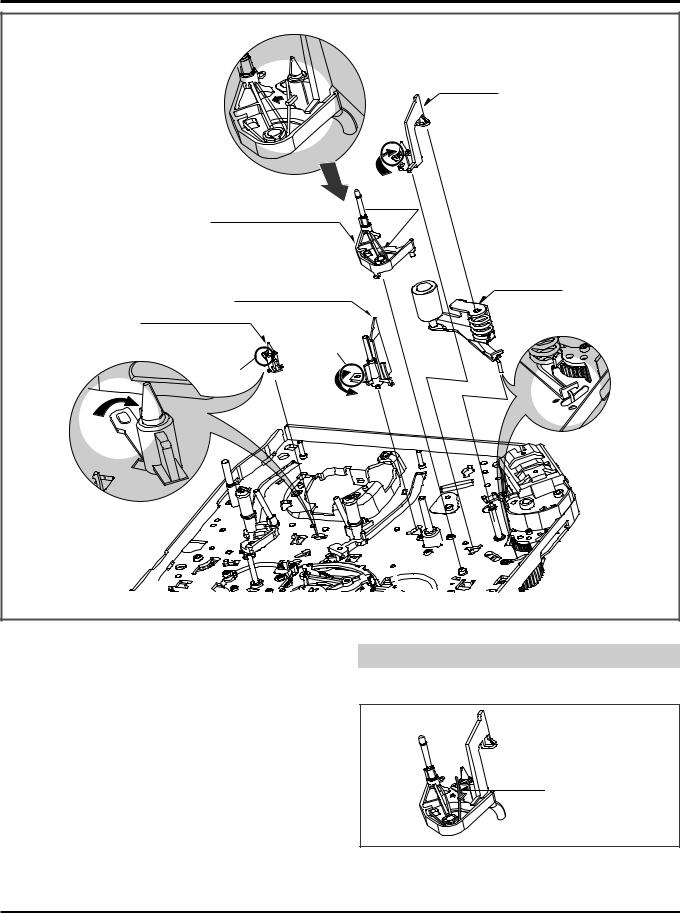
15. Support CST (Fig. A-5-1)
1)Break away the (A) part shown above Fig. A-5-1 from the Embossing of the Chassis in the clockwise direction, and lift up the Support CST.
16. Base Assembly P4 (Fig. A-5-2)
1)Break away the (B) part shown above Fig. A-5-2 from the Embossing of the Chassis in the counterclockwise direction and lift up the Base Assembly P4.
17. Opener Lid (Fig. A-5-3)
1)Hook the Spring Arm T/up on the Split digged under the Arm Assembly T/up.(Refer to Fig.A-5-4(D)).
2)Break away the (C) Part of the Opener Lid from the Embossing of the Chassis in the Clockwise direction and lift up the Opener Lid.
18. Arm Assembly T/up (Fig. A-5-4)
1)Confirm that the Spring Arm T/up is placed as above (No.17.1).
2) Lift up the Arm Assembly T/up.
NOTE
(1)When reassembling, unhook the Spring Arm T/up Shown above (No.17.1) to the original position.
Opener Lid 
Spring Arm T/up
 Arm Assembly T/up
19. Arm Assembly Pinch (Fig. A-5-5)
1) Lift up the Arm Assembly Pinch.
10
DECK MECHANISM DISASSEMBLY
(Fig. A-6-1) |
|
Belt Capstan |
|
|
|
|
|
|
|
|
|
|
(B) |
Motor Capstan |
|
|
|
|
|
|
|
|
|
(A) |
|
|
|
|
|
|
|
Washer(W1) |
|
|
|
|
|
Clutch Assembly D33 |
|
|
|
(Fig. A-6-2) |
|
(Fig. A-6-3) |
|
|
|
|
|
Washer(W2) |
Optional Parts |
||
Lever F/R |
|
Gear Assembly H-Up/D |
or |
Gear Assembly Up/D |
|
(Fig. A-6-4) |
|
(For Hi-Rewind Models) |
|
(For Normal Models) |
|
|
|
|
|
|
|
Hook(H1) |
|
Spring Up/D |
|
|
|
|
(C) |
Slide Washer |
|
|
|
|
|
|
|
|
|
|
|
|
|
|
(Fig. A-6-5) |
|
|
(B') |
|
|
|
|
(A') |
|
|
|
|
|
|
(S1) |
|
|
|
|
|
Fig. A-6 |
|
|
|
20. Belt Capstan (Fig. A-6-1)/
Motor Capstan (Fig. A-6-2)
1)Remove the Belt Capstan.
2)Remove three Screws(S1) on the back side of the Chassis and lift up the Motor Capstan.
NOTE
(1)When reassembling, Confirm the (A), (B) parts of Motor Capstan is located to the (A'), (B') of the Chassis.
21. Clutch Assembly D33 (Fig. A-6-3)
1)Remove the Washer(W1) and lift up the Clutch Assembly D33.
NOTE
(1)When reassembling, move the (C) part of the Lever F/R up and down, then confirm if it is returned to original position.
23. Gear Assembly H-Up/D or Gear Assembly Up/D (Fig. A-6-5)
1)Remove the Washer(W2) and lift up the Gear Assembly H-up/D.
2)Remove the Spring Up/D.
3)Remove the Slide Washer.
NOTE
22. Lever F/R (Fig. A-6-4)
1)Unhook the (H1) shown above Fig. A-6-4 and lift up the Lever F/R.
(1)Gear Assembly H-Up/D is for Hi-Rewind Models.
(2)Gear Assembly Up/D is for Normal Models except Hi-Rewind Models.
11
DECK MECHANISM DISASSEMBLY
|
Brake |
|
|
|
Capstan |
|
|
Hole (A)+(B) |
|
|
|
|
|
Brake |
|
|
(H2) |
Assembly Capstan |
|
Gear Cam |
|
|
|
|
|
Spring Capstan |
|
Guide |
|
(Fig. A-7-4) |
|
|
|
|
|
(S2) |
(H1) |
(S1) |
Bracket Assembly Jog |
|
|||
(Fig. A-7-2) |
|
|
(Fig. A-7-1) |
|
Gear Cam |
|
|
(Fig. A-7-3)
Fig. A-7
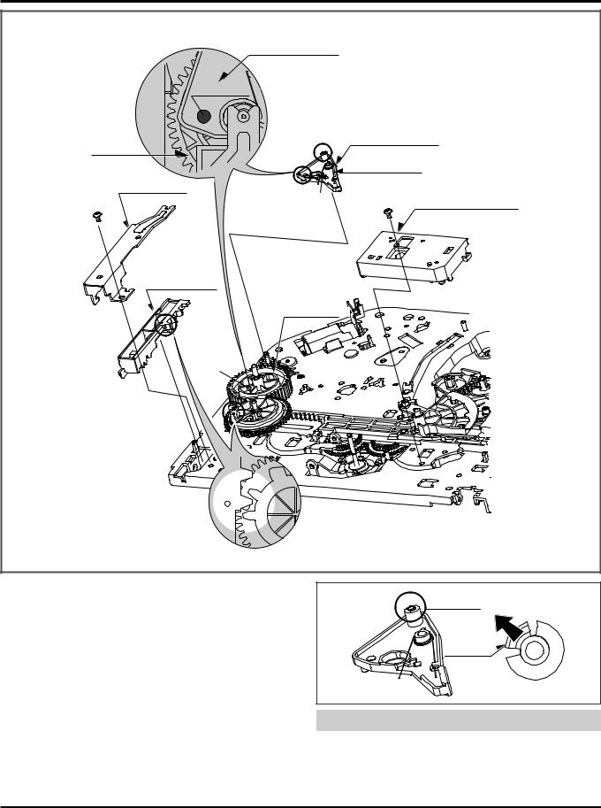
24. Bracket Assembly Jog (Fig. A-7-1)
1)Remove the Screw(S1) and lift up the Bracket Assembly Jog.
25. Guide Rack F/L (Fig. A-7-2)/ Gear Rack F/L (Fig. A-7-3)
1)Remove the Screw(S2) and lift up the Guide Rack F/L.
2)Lift up the Gear Rack F/L.
26. Brake Assembly Capstan (Fig. A-7-4)
1)Hook the Spring Capstan on the Hook(H1).
2)Unhook the Hook(H2) and lift up the Brake Assembly Capstan.(Refer to Fig. to the right)
Hook(H2)
Hook(H2)
NOTE
(1)When reassembling, confirm that the Hole(A) of the Brake Assembly Capstan is aligned to the Hole(B) of the Gear Cam.
(Refer to above Fig. A-7-4).
12
 Loading...