


http://getMANUAL.com


|
|
|
|
|
|
|
1/1 |
|||
|
|
|
|
|
|
|
||||
|
|
|
|
Service Technical Information |
|
|
|
|||
|
|
|
|
|
|
|
||||
|
|
|
|
|
|
|||||
|
|
|
|
|
|
|||||
|
|
|
|
|
|
|
|
|
|
|
|
MODEL NO. |
|
|
|
|
|
|
|||
|
|
|
TV−F2000 / F2400 |
|
|
|
|
|
|
|
|
|
|
|
|
|
|
|
|
|
|
|
SUBJECT |
|
|
|
|
|
|
|||
|
|
|
Notes on repairing flat CRT TV set |
REF.No. |
:G − 99 − 076 − E0 |
|||||
|
|
|
|
|
|
DATE |
:02. MAR. 2000 |
|
||
|
|
|
|
|
|
|||||
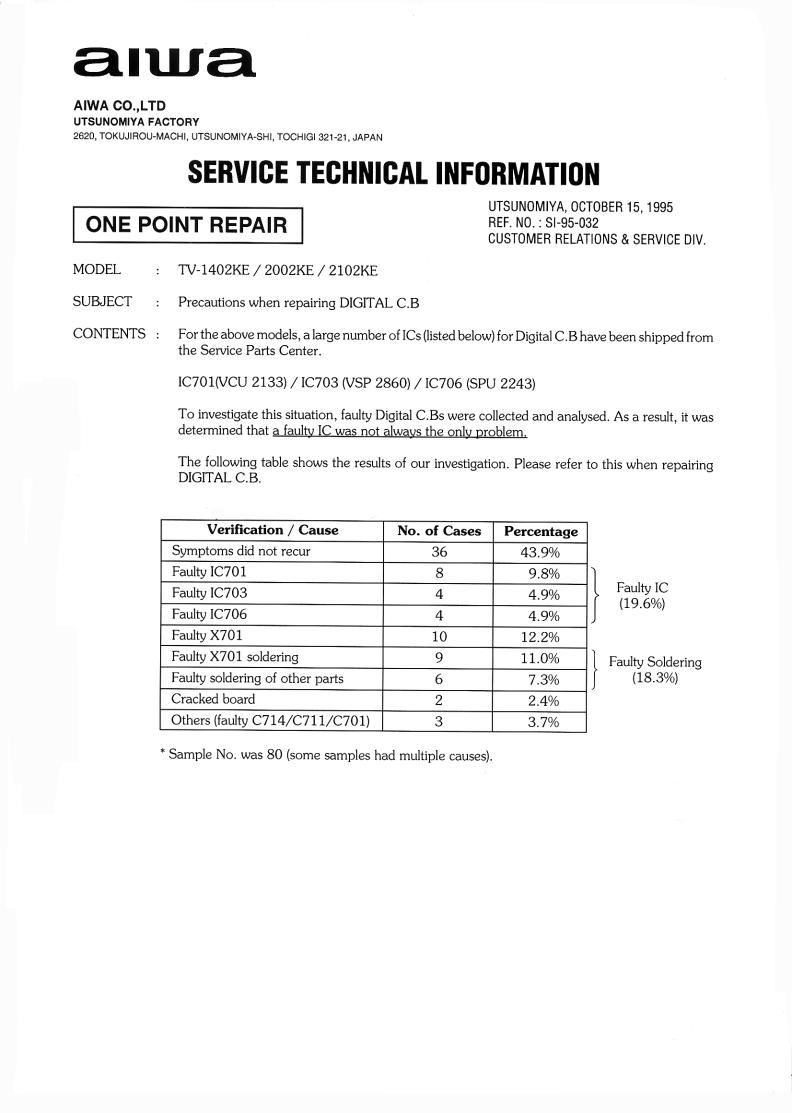
<CONTENTS>
Pay attention to the following notes when repairing flat CRT a TV set. When repairing a unit, DO NOT LEAVE the degaussing cable disconnected.
Conventional TV sets allow repairing work with a degaussing cable removed.
When repairing a TV set with flat CRT, however, the instruction below must be followed. The instruction is provided on the service manual also.
Make this known to all staff concerned.
Notes on repairing:
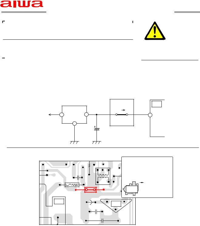
DO NOT turn on the power of a TV set with a flat CRT when a degaussing coil is removed.
Be sure to connect a dummy load when removing a degaussing coil. Scheme 1: Use another degaussing coil to be connected for repairing.
Scheme 2: Use a 6.8Ω, 20W resistor, as the jig to be connected to the connector of degaussing coil.
Turning on the power of a unit with neither degaussing coil or dummy load results in opening a fixed resistor R848, which is inserted in parallel to the degaussing coil.
The following shows relations between the models concerned and the cement−resistors:
|
Model name |
R848 |
Type |
|
|
|
|
|
|
|
TV−F21ST1 |
33Ω/2W |
cement resistor |
|
|
|
|
|
|
|
TV−F25ST1 |
27Ω/2W |
cement resistor |
|
|
TV−F2400 |
|
|
|
|
|
|
|
|
|
TV−F2000 |
56Ω/2W |
cement resistor |
|
|
|
|
|
|
|
|
|
|
|
If the resistor opens, noises appear in horizontal directions on screen.
Also pay attentions to information about the flat CRT models to be released in the future. Component values of the dummy resistors will be announced as occasion arises, and will be contained in the service manual. Always take notice of the information.
|
G |
R |
Code No. |
Access Code |
Modified Ser. No. |
Parts Schedule |
|
− |
− |
− |
− |
− |
− |
|
|
|
|
|
|
|

1/1
Service Technical Information
MODEL NO. |
SUFFIX |
|
|
|
|
|
|
|
|
TV− F2000 / F2400 |
U / U |
|
|
|
|
|
|
|
|
|
|
|
|
|
|
|
|
|
|
|
|
|
|
|
|
|
|
|
|
SUBJECT |
|
|
|
|
|
|
|
|
|
Notes on repairing |
|
|
|
REF.No. |
:G − 99− 076− E1 |
||||
|
|
|
|
DATE |
:18. FEB. 2002 |
|
|||
|
|
|
|
||||||
REVISION : Amended the SUBJECT and the <CONTENTS>.
<CONTENTS>
Pay attention to the following notes when repairing the TV− F2400/F2000.
Do not leave the degaussing cable disconnected when repair a unit. Conventional TV sets allow repairing work with a degaussing cable removed.
Turning on the power of a TV− F2400 / F2000 with neither degaussing coil results in breaking a cement resistor which is inserted in parallel to the degaussing coil.
Be sure to connect a dummy load when removing a degaussing coil. Scheme 1 :Use another degaussing coil to be connected for repairing.
Scheme 2 :Use a 6.8Ω − 20W resistor, as the jig to be connected to the connector of degaussing coil.
Turning on the power of a unit with neither degaussing coil or dummy load results in opening a fixed resistor which is inserted in parallel to the degaussing coil.
The following shows relations between the models concerned and the cement− resistors.
|
Model |
Ref No. |
Value |
|
Parts Code |
Affected Serial No. |
|
||||
|
|
|
|
|
|
|
|
|
|||
|
TV− F21ST1 |
R848 |
56W/2W |
87− A00− 659− 010 |
S |
9C |
~ |
|
|||
|
|
|
|
|
|
|
|
|
|||
|
TV− F25ST1 |
R848 |
27W/2W |
87− A00− 655− 010 |
S |
9C |
~ |
|
|||
|
|
|
|
|
|
|
|
|
|
|
|
|
TV− F2400 |
R801 |
27W/2W |
87− |
A00− |
661− |
010 |
|
All |
|
|
|
|
|
|
|
|
|
|
|
|
|
|
|
TV− F2000 |
R801 |
56W/2W |
87− |
A00− |
665− |
010 |
|
All |
|
|
|
|
|
|
|
|
|
|
|
|
|
|
|
|
|
|
|
|
|
|
|
|
|
|
Note :The cement− resistor is not installed, if the serial number of unit is not included in table above.
If the resistor opens, noises may appear in horizontal directions on screen.
|
G |
R |
Code No. |
Access Code |
Modified Ser. No. |
Parts Schedule |
|
− |
− |
− |
− |
− |
− |
|
|
|
|
|
|
|
|
|
|
|
|
|
|
1/1 |
|||
|
|
|
|
|
|
|
||||
|
|
|
|
Service Technical Information |
|
|
|
|||
|
|
|
|
|
|
|
||||
|
|
|
|
|
|
|||||
|
|
|
|
|
|
|||||
|
|
|
|
|
|
|
|
|
|
|
|
MODEL NO. |
|
|
|
|
|
|
|||
|
|
|
TV−CN143 / CN203 |
|
|
|
|
|
|
|
|
|
|
|
|
|
|
|
|
|
|
|
SUBJECT |
|
|
|
|
|
|
|||
|
|
|
The screen is too dark |
|
REF.No. |
:G − A0 − 032 − E0 |
||||
|
|
|
|
|
|
DATE |
:31. MAY. 2000 |
|
||
|
|
|
|
|
|
|||||
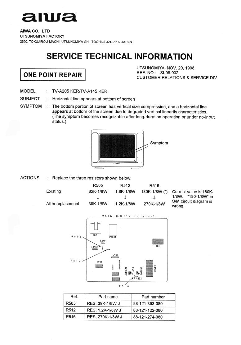
<CONTENTS>
The screen voltage falls down due to an abnormality of the capacitor C901 thereby causing the screen to become dark.
Take the following countermeasure when this problem is pointed out.
<COUNTERMEASURE> Replace the capacitor C901.
Always make sure to use the specified part because the manufacturer of this part has been changed.
NK.PWB
C901
|
Parts Name |
Parts Code |
|
|
|
|
CAP,CER 1000P−2KB |
87−016−037−060 |
|
|
|
|
Ref. |
Parts Code |
Description |
|
|
Remarks |
||||
C901 |
87−016−037−060 |
CAP,CER 1000P−2KB |
|
|
− |
|||||
|
|
|
|
|
|
|
|
|
|
|
|
|
|
|
|
|
|
|
|
|
|
G |
|
R |
|
Code No. |
|
Access Code |
Modified Ser. No. |
|
Parts Schedule |
|
− |
|
− |
|
− |
|
− |
S 03 |
|
− |
|
|
|
|
|
|
|
|
|
|
|
|
|
|
|
|
|
|
|
1/1 |
|||
|
|
|
|
|
|
|
||||
|
|
|
|
Service Technical Information |
|
|
|
|||
|
|
|
|
|
|
|
||||
|
|
|
|
|
|
|||||
|
|
|
|
|
|
|||||
|
|
|
|
|
|
|
|
|
|
|
|
MODEL NO. |
|
|
|
|
|
|
|||
|
|
|
TV−AT215 |
|
|
|
|
|
|
|
|
|
|
|
|
|
|
|
|
|
|
|
SUBJECT |
|
|
|
|
|
|
|||
|
|
|
The remote control is not effective |
REF.No. |
:G − A0 − 035 − E0 |
|||||
|
|
|
|
|
|
DATE |
:05. JUN. 2000 |
|
||
|
|
|
|
|
|
|||||
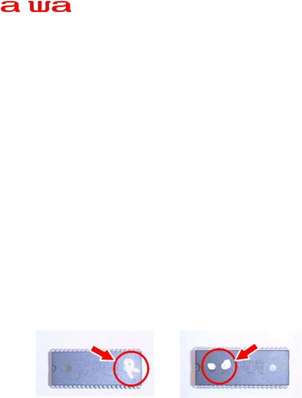
<CONTENTS>
In this set, after successive operations of changing the channel are made using the remote control, there are times when the remote control becomes ineffective.
Please take the following countermeasures for such sets.
Further, although this condition gets recovered when the AC cord of the main unit is removed and then inserted again in to the power socket, the same condition occurs again if the above operation is made again.
<COUNTERMEASURE>
Please replace the component with the one specified below.Take care about the differences between the regional models.
|
A:IC, ST6387−OTP 6373 |
Rumania Version |
The mark "R" is present on the top surface of |
|||||
|
|
|
|
|
the IC. |
|||
|
|
|
|
|
|
|
|
|
|
B:IC, ST6387−OTP 6331 |
Poland Version |
There are marks of two white dots on the top |
|||||
|
|
|
|
|
surface of the IC. |
|||
|
|
|
|
|
|
|
|
|
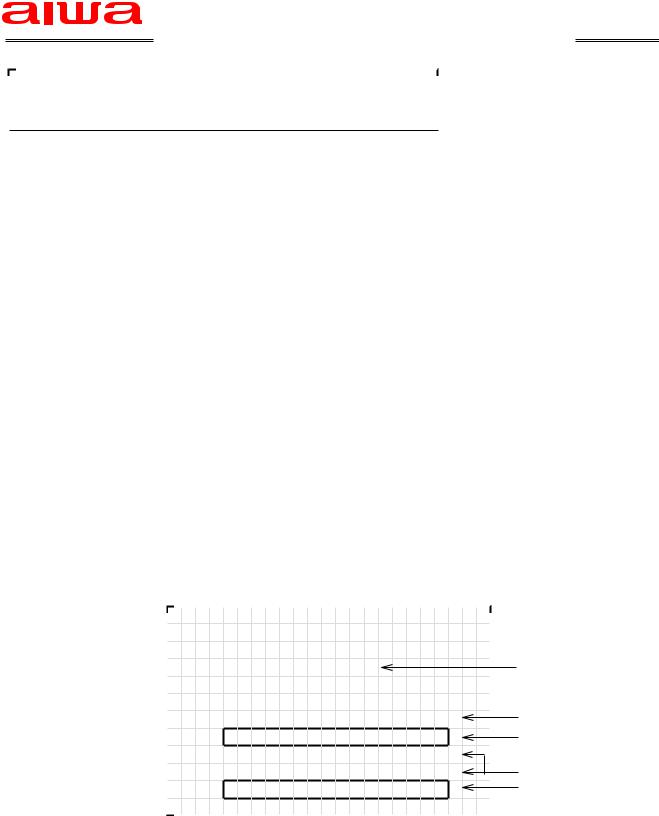
Method of discriminating between the microcomputer IC of different regional models |
||||||||
|
|
|
|
|
|
|
|
|
|
|
|
A: Rumania Version |
|
B: Poland Version |
|
||
|
|
|
|
|
|
|
|
|
|
|
|
Marking of the "R" mark |
|
|
Marking of two white dots |
|
|
|
|
|
|
|
|
|
|
|
|
|
|
|
|
|
|
|
|
|
|
|
|
|
|
|
|
|
|
Ref. |
Parts Code |
Description |
|
Remarks |
|||||
|
|
IC1 |
87−JB1−626−010 |
IC, ST6387−OTP 6373 |
|
for Romania version |
||||
|
|
IC1 |
87−JB1−627−010 |
IC, ST6387−OTP 6331 |
|
for Poland, Czech, Slovakia |
||||
|
|
|
|
|
|
|
|
|
|
|
|
|
|
|
|
|
|
|
|
|
|
G |
|
R |
|
Code No. |
|
Access Code |
|
Modified Ser. No. |
Parts Schedule |
|
− |
|
− |
|
− |
|
− |
|
|
− |
20.AUG.2000 |
|
|
|
|
|
|
|
|
|
|
|
1/1
Service Technical Information
MODEL NO. |
|
|
TV− C202 |
|
|
TV− C202S |
|
|
SUBJECT |
|
|
No power |
REF.No. |
:G − A0− 117− E0 |
|
DATE |
:02. MAR. 2001 |
<CONTENTS>
No power due to open IC PROTECTOR (ICP,PR 801) caused by a rush current.
<COUNTERMEASURE>
Replace the IC Protector (PR801 1.5A)with one that has higher current capacity(4A). SCHEMATIC DIAGRAM
|
|
|
PR801 |
T602 |
|
|
|
IC804 |
1.5A |
4A |
|
Power Supply |
3 |
1 |
|
1 E15 |
|
12V REG |
|
||||
|
|
|
|
|
|
|
|
2 |
|
|
|
|
|
|
C825 |
|
|
WIRING |
MAIN C.B Pattern Side |
|
Expansion Figure |
F |
|
R |
|
|
E |
R |
|
A |
O |
|
R |
N |
|
|
T |
|
|
PR801 |
|
|
T602 |
|
PR801 |
|
T602 |
Q602 |
|
|
|
|
Ref. |
Parts Code |
Description |
|
|
Remarks |
|||||
|
|
|
|
|
|
|
|
|
|
||
PR801 |
87− A90− 094− 080 |
PROTECTOR,4A 491SERIES 60V |
|
|
− |
||||||
|
|
|
|
|
|
|
|
|
|
|
|
|
|
|
|
|
|
|
|
|
|
|
|
G |
|
R |
|
Code No. |
|
Access Code |
|
Modified Ser. No. |
|
Parts Schedule |
|
|
|
|
|
|
|
|
|
|
|
|
|
− |
|
− |
|
− |
|
− |
|
− |
|
− |
|
|
|
|
|
|
|
|
|
|
|
|
|
1/2
Service Technical Information
MODEL NO.
TV− SA2151/A2118/A2110/A2018/A2010
SUBJECT
Distinction Switch setting up procedure |
REF.No. |
:G − A0− 125− E0 |
||
|
|
DATE |
:10. APR. 2001 |
|
|
|
|||
<CONTENTS>
Setup procedure for Distinction Switch was not described in the service manuals below.
TV− SA2151 |
09− 007− 420− 8S1 |
|||
TV− A2110 / A2118 |
09− |
007− |
416− |
7S3 |
TV− A2010 / A2018 |
09− |
007− |
420− |
5S1 |
Please refer to the following procedure when setting Distinction Switches.
<COUNTERMEASURE>
1.Press TEST key of a Jig remote control and set to the AGING mode.
2.Press SYSTEM key of a jig remote control and set to the Distinction Switch mode.
3.Make sure the lower part in the upper row on the screen 1:KE 1 8:SH4, are shown in red as the below table. If not press the numeric key to make the items in question become red.
|
Model Name |
Item |
Key |
|
|
TV− SA2151 |
SH3 |
7 |
|
|
TV− A2118 |
SH2 |
6 |
|
|
TV− A2110 |
KE2 |
2 |
|
|
TV− A2018 |
SH2 |
6 |
|
|
TV− A2010 |
KE2 |
2 |
|
|
|
|
|
|
Fig.1 Items to be selected by model
1 |
: K E 1 |
|
|
|
5 |
: |
S H 1 |
|
|
|
||||
2 |
: K E 2 |
|
|
|
6 |
: |
S H 2 |
|
|
|
||||
3 |
: I |
N D O 1 |
|
7 |
: |
S H 3 |
|
Red |
|
|||||
4 : I |
N D O 2 8 : |
S H 4 |
|
|
|
|||||||||
|
0 |
1 |
2 |
3 |
4 |
5 |
6 |
7 |
8 |
9 |
A B C D E F |
Address 0 F |
||
|
1 |
1 |
0 |
1 |
0 |
0 |
0 |
0 |
1 |
1 |
1 |
1 0 0 0 1 |
Date |
0 F |
|
1 1 1 1 1 1 1 1 1 1 1 1 1 1 1 1 |
|
|
|||||||||||
|
0 |
1 |
2 |
3 |
4 |
5 |
6 |
7 |
8 |
9 |
A B C D E F |
Address 10 1F |
||
|
1 |
0 |
1 |
1 |
0 |
0 |
1 |
0 |
0 |
0 |
1 |
1 0 0 0 0 |
Date |
10 F |
Fig.2 Screen shot on the distinction switch set up mode |
(Example : TV− SA2151) |
|||||||||||||
4. |
Check to see if the data of address 0-1F match the Fig3 (next page) or not. |
|
||||||||
|
|
If not, amend them as follows: |
|
|
|
|||||
|
|
|
CHANNEL UP/DOWN |
Select appropriate data (selected data appear in red) |
||||||
|
|
|
VOLUME UP/DOWN |
Change value (0 or 1) |
|
|
|
|||
5. |
After data input and/or confirmation is completed, Press TEST key to go back to the |
|||||||||
|
|
AGING mode. |
|
|
|
|
|
|||
|
|
|
|
|
|
|
|
|
|
|
|
G |
R |
|
Code No. |
|
Access Code |
|
Modified Ser. No. |
|
Parts Schedule |
|
− |
− |
|
− |
|
− |
|
− |
|
− |
|
|
|
|
|
|
|
|
|
|
|
1 |
: K E 1 |
5 |
: S H |
1 |
|
|
2 |
: K E 2 |
6 |
: S H |
2 |
|
|
3 |
: I |
N D O 1 |
7 |
: S H 3 |
Red |
|
4 : I |
N D O 2 8 : S H 4 |
|
||||
|
0 1 2 3 4 5 6 7 8 9 A B C D E F |
|
||||
|
1 1 0 1 0 0 0 0 1 1 1 1 0 0 0 1 |
|
||||
|
1 1 1 1 1 1 1 1 1 1 1 1 1 1 1 1 |
|
||||
|
0 1 2 3 4 5 6 7 8 9 A B C D E F |
|
||||
|
1 0 1 1 0 0 1 0 0 0 1 1 0 0 0 0 |
|
||||
|
|
TV− SA2151 |
|
|
||
1 |
: K E 1 |
5 |
: S H 1 |
|
|
2 |
: K E 2 |
6 |
: S H 2 |
|
|
3 |
: I |
N D |
7 |
: S H 3 |
Red |
4 : I |
N D O 2 8 : S H 4 |
|
|||
|
0 1 2 3 4 5 6 7 8 9 A B C D E F |
|
|||
|
1 1 0 1 0 0 0 0 1 1 1 1 0 0 0 0 |
|
|||
|
1 1 1 1 1 1 1 1 1 1 1 1 1 1 1 1 |
|
|||
|
0 1 2 3 4 5 6 7 8 9 A B C D E F |
|
|||
|
0 0 1 1 0 0 1 0 0 0 1 1 0 0 0 0 |
|
|||
|
|
TV− |
A2118 |
|
|
1 |
: K E 1 |
5 |
: S H 1 |
|
|
2 |
: K E 2 |
6 |
: S H 2 |
Red |
|
3 |
: I |
N D |
7 |
: S H 3 |
|
4 : I |
N D O 2 8 : S H 4 |
|
|||
|
0 1 2 3 4 5 6 7 8 9 A B C D E F |
|
|||
|
1 0 0 1 0 0 0 0 1 1 1 1 0 0 0 0 |
|
|||
|
1 1 1 1 1 1 1 1 1 1 1 1 1 1 1 1 |
|
|||
|
0 1 2 3 4 5 6 7 8 9 A B C D E F |
|
|||
|
0 0 1 1 0 0 1 0 0 0 1 1 0 0 0 0 |
|
|||
|
|
|
TV− A2018 |
|
|
|
|
|
2/2 |
1 : K E 1 |
5 |
: S H 1 |
|
2 : K E 2 |
6 |
: S H 2 |
|
3 : I |
N D O 1 7 : S H 3 |
||
4 : I |
N D O 2 8 : S H 4 |
||
0 1 2 3 4 5 6 7 8 9 A B C D E F |
|||
1 0 0 1 0 0 0 0 1 1 1 1 0 0 0 0 |
|||
1 1 1 1 1 1 1 1 1 1 1 1 1 1 1 1 |
|||
0 1 2 3 4 5 6 7 8 9 A B C D E F |
|||
0 0 1 1 0 0 1 0 0 0 1 1 0 0 0 0 |
|||
|
TV− |
A2110 |
|
1 |
: K E 1 |
5 |
: S H 1 |
|
2 |
: K E 2 |
6 |
: S H 2 |
|
3 |
: I |
N D |
7 |
: S H 3 |
4 : I |
N D O 2 8 : S H 4 |
|||
|
0 1 2 3 4 5 6 7 8 9 A B C D E F |
|||
|
1 0 0 1 0 0 0 0 1 1 1 1 0 0 0 0 |
|||
|
1 1 1 1 1 1 1 1 1 1 1 1 1 1 1 1 |
|||
|
0 1 2 3 4 5 6 7 8 9 A B C D E F |
|||
|
0 0 1 1 0 0 1 0 0 0 1 1 0 0 0 0 |
|||
|
|
TV− |
A2010 |
|
Fig.3 Distinction switch set up data for each model
|
|
|
|
|
|
|
1/1 |
|||
|
|
|
|
|
|
|
||||
|
|
|
|
Service Technical Information |
|
|
|
|||
|
|
|
|
|
|
|
||||
|
|
|
|
|
|
|||||
|
|
|
|
|
|
|||||
|
|
|
|
|
|
|
|
|
|
|
|
MODEL NO. |
|
|
|
|
|
|
|||
|
|
|
TV− F2000 / F2100 / F2400 / F2500 |
|
|
|
|
|
|
|
|
|
|
|
|
|
|
|
|
|
|
|
SUBJECT |
|
|
|
|
|
|
|||
|
|
|
Vertical line appears on the screen |
|
REF.No. |
:G − A1− 011− E0 |
||||
|
|
|
|
|
|
DATE |
:06. JUN. 2001 |
|
||
|
|
|
|
|
|
|||||
<CONTENTS>
A vertical line may appear on TV screen when VCD player or DVD player is connected to input terminal for playback.
Same problems rarely happen on other equipment, too.
If such problems are experienced, take countermeasure below.
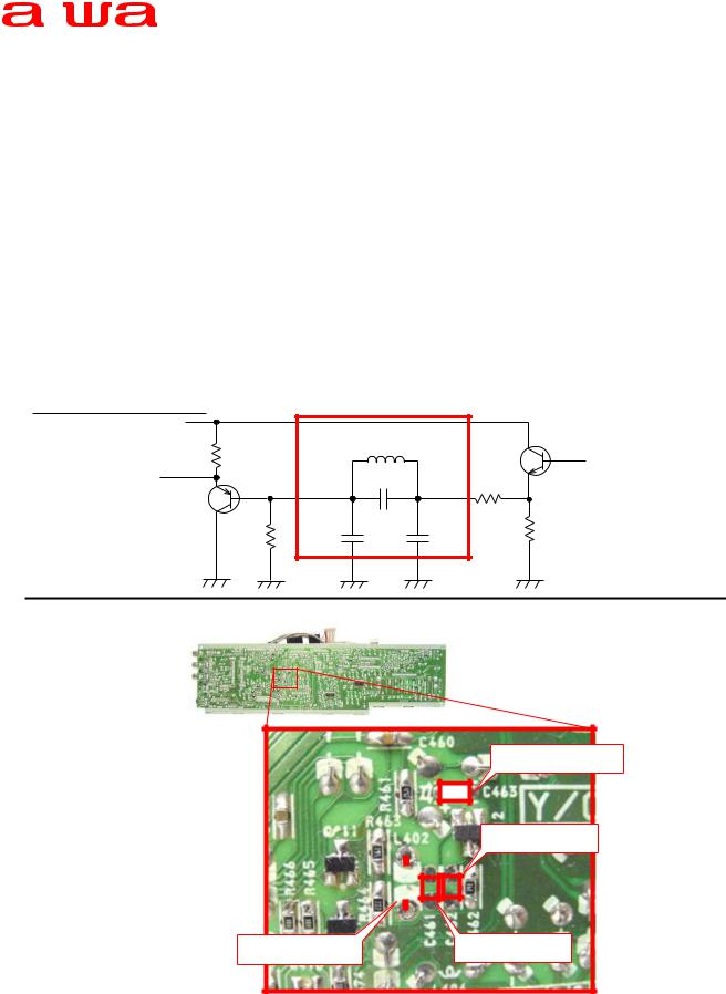
<COUNTERMEASURE>
Add a filter (when fitting L402, remove jumper wire). SCHEMATIC DIAGRAM Additional Circuit
|
|
L402 |
Q413 |
|
|
12 H |
|
VIDEO− IN |
|
C461 |
|
|
|
27PF |
R463 |
Q412 |
|
|
|
|
|
C462 |
C463 |
|
R462 |
39PF |
100PF |
|
|
|
VIDEO− OUT
R464
WIRING
C463:100pF
C462:39pF
|
|
|
|
|
|
|
|
|
|
|
|
|
|
|
|
|
|
|
|
|
|
|
|
|
|
|
|
|
|
|
|
|
|
|
|
|
|
|
|
L402:12 H |
|
|
|
|
C461:27pF |
|
|
|||
|
|
|
|
|
|
|
|
|
|
|
|
|
|
|
|
|
|
Ref. |
Parts Code |
|
Description |
|
|
|
|
|
|
Remarks |
|||||
|
|
|
|
|
|
|
|
|
|
|
|
|
|
|
|
|
|
|
− |
SV− T00− 117− 01J |
|
KIT,TV− F2100/F2500 V NOISE |
|
− |
|||||||||
|
|
|
|
|
|
|
|
|
|
|
|
|
|
|
|
|
|
|
|
|
|
|
|
|
|
|
|
|
|
|
|
|
|
G |
|
R |
|
Code No. |
|
|
Access Code |
|
|
|
Modified Ser. No. |
|
Parts Schedule |
|||
|
|
|
|
|
|
|
|
|
|
|
|
|
|
|
|
|
− |
|
− |
|
− |
|
|
− |
|
|
|
S 12 |
|
13.JLY.2001 |
|||
|
|
|
|
|
|
|
|
|
|
|
|
|
|
|
|
|

|
|
|
|
|
|
|
1/1 |
|||
|
|
|
|
|
|
|
||||
|
|
|
|
Service Technical Information |
|
|
|
|||
|
|
|
|
|
|
|
||||
|
|
|
|
|
|
|||||
|
|
|
|
|
|
|||||
|
|
|
|
|
|
|
|
|
|
|
|
MODEL NO. |
|
|
|
|
|
|
|||
|
|
|
TV− SE1430 / SE2130 / C1400 |
|
|
|
|
|
|
|
|
|
|
|
|
|
|
|
|
|
|
|
SUBJECT |
|
|
|
|
|
|
|||
|
|
|
Revised set up procedure |
|
REF.No. |
:G − A1− 017− E0 |
||||
|
|
|
|
|
|
DATE |
:11. JUN. 2001 |
|
||
|
|
|
|
|
|
|||||
<CONTENTS>
For betterment of the "step by step instructions" on the SET UP procedure in the Service Manuals, we add one more step as described below.
Correction(add the red colored sentence)
Step "No.3" shown in red to be incerted to the procedure.
1.Use the numeric keys on the remote control to set the receiving channel to Pr91.
2.Set Sharpness on the Picture Menu screen to 0.
3.Press MENU button on the remote control twice to back to the normal mode. (Channel Pr91 appears on the screen).
4.Press the buttons on remote control in the following order:
Skip(R) Move(G) Menu
The following menu will appear on the TV screen (the menu can be seiched by the " P /
/ " button on the remote control).
5.To terminate the menu screen, press the MENU button on the remote control,or the power button on the TV or remote control.
<NOTE>
Pressing three button described in the process 4 above must be done with a second, or it will not get into the Service Mode.
G |
R |
Code No. |
Access Code |
Modified Ser. No. |
Parts Schedule |
− |
− |
− |
− |
− |
− |
|
|
|
|
|
|
 Loading...