


FK1462 P0109YI
JK-1MED
HANDS FREE COLOR VIDEO INTERCOM MASTER MONITOR STATION INTERPHONE VIDEO COULEUR MAINS LIBRES MONITEUR MAÎTRE HANDENVRIJE KLEURENVIDEOFONIE MONITOR-HOOFDPOST
 JK-1MED
Master monitor station
Moniteur maître
Monitor-hoofdpost
INSTALLATION & OPERATION MANUAL MANUEL D’INSTALLATION ET D’UTILISATION INSTALLATIEEN GEBRUIKSHANDLEIDING
English
Français
Nederlands
PRECAUTIONS
General Prohibitions |
Prohibition to Dismantle the Unit |
Prohibition on Subjecting the Unit to Water |
General Precautions |
 WARNING
(Negligence could result in death or serious injury.)
 1. High voltage is present internally. Do not open the case. Electric shock could result.
 2. Do not dismantle or alter the unit. Fire or electric shock could result.
 3. Do not connect any non-specified power source to the +, - terminals. Also, do not install two power supplies in parallel to a single input. Fire or damage to the unit could result.
 4. Keep the unit away from water or any other liquid. Fire or electric shock could result.
 5. Do not put any metal or flammable material into the unit through the openings. Fire or electric shock could result.
 6. Do not use power supply with a voltage other than specified. Fire or electric shock could result.
 7. Do not connect any terminal on the unit to an AC power line. Fire or electric shock could result.
 CAUTION
(Negligence could result in injury to people or damage to property.)
 1. Do not install or make any wire terminations while power supply is plugged in. It can cause electrical shock or damage to the unit.
 2. Before turning on power, make sure wires are not crossed or shorted. If not, fire or electric shock could result.
 3. When mounting the unit on a wall, install the unit in a convenient location, but not where it could be jarred or bumped. Injury could result.
 4. For power supply, use Aiphone power supply model or model specified for use with system. If non-specified product is used, fire or malfunction could result.
 5. Do not install the unit in any of the following locations. Fire, electric shock, or unit trouble could result.
*Places under direct sunlight or places near heating equipment that varies in temperature.
*Places subject to dust, oil, chemicals, etc.
*Places subject to moisture and humidity extremes, such as bathrooms, cellars, greenhouses, etc.
*Places where the temperature is quite low, such as inside a refrigerated area or in front of an air conditioner.
*Places subject to steam or smoke (near heating or cooking surfaces).
*Where noise generating devices such as dimmer switches or inverter electrical appliances are close by.
*Do not install the unit in locations subject to frequent vibration or impact.
 6. Do not put anything on the unit or cover the unit with cloth, etc. Fire or unit trouble could result.
 7. Do not press on the LCD or subject it to a high impact. The LCD glass could be punctured and result in an injury.
 8. If the LCD is punctured, do not allow skin contact with the liquid crystal inside. Inflammation could result.
*If liquid crystal is ingested, immediately gargle with water and seek medical attention.
*If contact with the eyes or skin occurs, clean with pure water for at least 15 minutes and seek medical attention.
General Precautions
1.Keep the unit more than 1 m away from radio or TV set.
2.This unit is for indoor use only. Do not use outdoors.
3.In areas where broadcasting station antennas are close by, the intercom system may be affected by radio frequency interference.
4.As to other manufacturer's devices (such as sensor, detectors, door releases) used with this system, comply with the Specifications and Warranty conditions that the manufacturers or venders present.
5.Keep the intercom wires at least 30 cm (12") away from AC 100-240 V lines. Noise and malfunction could result.
6.If the unit is down or does not operate properly, unplug the power supply or turn off the JK-1MED and JK-1HD (JK-1SD) POWER switches.
7.The unit is for wall-mount use only. For desktop applications, use desk stand.
8.When wall-mounted, the top of the unit may darken. This does not indicate a malfunction.
9.The unit case may become warm with use, but this is not a unit malfunction.
10.If a cellular phone is used close by, the unit may malfunction.
11.The LCD panel is manufactured with very high precision techniques. Small portions of the panel may fail to light up or some portions may be constantly lit, but this does not indicate a unit malfunction. Please be aware of this in advance.
12.Refrain from using the color monitor station in sunlit areas.
13.At night, due to reduced lighting on the object, the monitor sees more noise and the face becomes more difficult to see, but this is not malfunction.
14.Talk within 50 cm (20") or less from the unit. If you stand too far away, it may be difficult for the other person to hear the communication.
15.If there are loud noises around the unit (such as music playing or children crying), the sound may break up and be difficult to hear.
16.During communication, if you speak before the other person has finished talking, your voice may not come through clearly. Communication will proceed smoothly if you wait until the other person has finished before speaking.
17.At a gate or porch illuminated by a fluorescent lamp, the picture may vary, but this is not a malfunction.
18.When outside temperature lowers sharply after rainfall, etc., the inside of the camera may fog up slightly, causing a blurry picture, but this is not a malfunction. Normal operation will be restored when moisture evaporates.
19.Due to the environmental sound around the unit, it may hinder smooth communication, but this is not a malfunction.
20.The outline of video images displayed by video door station may differ from that of the actual person(s) or background, but this is not a malfunction.
21.If the screen of a video door station freezes during wintertime, the picture may become difficult to see or the CALL button may not move, but this is not a malfunction.
22.Aiphone assumes no responsibility for corruption of saved information (such as changes to or deletion of saved information). Please be aware of this in advance.
23.This unit is not compatible with JA, JF, KB, and KC series units.
24.Warm-color lighting shining on the door station may change the tint of the picture on the monitor.
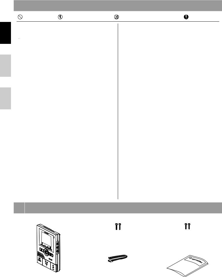
1 PACKAGE CONTENTS
JK-1MED |
Mounting screws x 2 |
Wood mounting screws x 2 |
Option connector |
Installation & Operation manual |
- 2 -
|
|
|
|
|
|
|
|
2 |
INSTALLATION |
|
|
|
|||
|
|
|
|
|
|
|
|
|
2-1 |
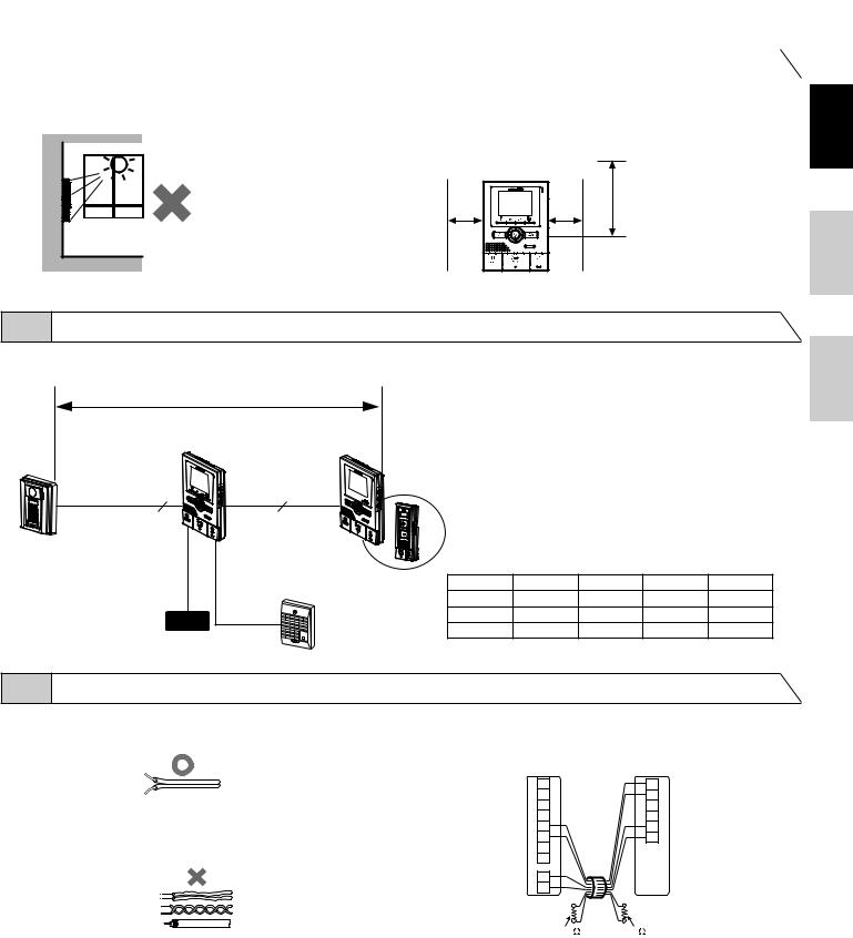
Mounting locations |
|
|
|
||
|
1 Install the master monitor station in a place |
2 The master monitor station has switches on |
3 Allow at least 15 cm (6") of vertical open |
||||
|
where the screen is not exposed to direct |
both sides. Allow at least 5 cm (2") of open |
space from the center of the mounting |
||||
|
sunlight. |
space on either side. |
bracket in order to mount the master |
||||
|
|
|
|
|
|
monitor station. |
|
2 |
JK-1MED |
|
3 |
|
|
||
|
+ 5 cm |
+ 15 cm |
|
+ 5 cm |
|
(6") |
|
(2") |
|
(2") |
|
|
|
English
Français
2-2 Wiring method, wiring distance
Wire the units from station-to-station (daisy-chained).
|
A |
|
|
JK-DA |
|
JK-1HD |
|
JK-DV |
|
||
|
|
||
JK-DVF |
JK-1MED |
|
|
|
JK-1SD |
||
2 |
4 |
||
|
|
B |
C |
|
Ø 0,65 mm |
22 AWG |
Ø 1,0 mm |
18 AWG |
|
|
IER-2 |
|
||||
|
|
A |
50 m |
165' |
100 m |
330' |
|
|
|
|
|||||
PS-1820 |
PS18 |
|
B |
5 m |
16' |
10 m |
33' |
PS-1810DIN |
|
|
C |
75 m |
245' |
150 m |
490' |
PS-1820DIN |
|
|
|
|
|
|
|
2-3 Cable |
|
|
1 Use PVC jacket with PE (polyethylene) insulated cable |
3 When using a cable with unused conductors, terminate both ends of |
|
|
the unused pair(s) with a 120 Ω resistor. |
|
|
JK-1MED |
JK-1HD/JK-1SD |
(x2) |
A1 |
B1 |
|
A2 |
B2 |
|
S |
SW |
2 Never use individual conductors, twisted pair cable or coaxial cable. |
S |
SW |
B1 |
+ |
|
|
B2 |
- |
|
L |
|
|
L |
|
|
+ |
|
|
- |
|
|
120 |
120 |
Nederlands
- 3 -
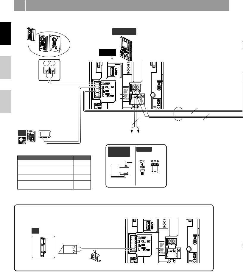
3 WIRING
Insert wires securely into each terminal as shown.
English |
DOOR Video door station |
||
|
|
|
|
JK-DA |
|
|
|
Français |
JK-DV |
JK-DVF |
|
A1 |
A2 |
|
|
|
|
||
|
|
2 |
|
|
|
NP |
|
Nederlands |
|
|
|
Optional call extension speaker |
|
||
IER-2 |
|
|
|
OP |
1 E |
|
|
|
|
2 |
|
IER-2 |
|
NP |
|
|
|
|
|
Presence of sound from IER-2 |
|
||
|
Item |
|
Sound |
Chime tone from door station (8-1) |
○ |
||
Alarm sound during external sensor |
○ |
||
input (8-15) |
|
|
|
|
|
|
|
Audio during instant voice call (8-1) |
|
||
Chime tone during room-to-room |
|
||
communication (8-4) |
|
||
|
|
||
Door release |
|
|
|
JK-1MED Master monitor station
OPTION
CONNECTOR
|
2 |
|
|
NP |
2 |
P |
2 |
P |
|
|
-+
DC 18 V
Power supply |
|
||
PS-1810DIN/ |
PS-1820 |
NP: Non-polarized |
|
P: Polarized |
|||
PS-1820DIN |
|
||
|
|
||
230V AC N |
|
|
|
L |
|
|
|
IN 230V~ 50/60Hz NL |
|
|
|
1A - + |
|
|
|
- |
100V - 240V - |
18V DC |
|
+ |
2 A |
||
18V DC 1A (PS-1810DIN) |
50/60 Hz |
||
|
|||
18V DC 2A (PS-1820DIN) |
|
|
|
An EL-12S (AC 12 V 0.125 A, DC 12 V 0.2 A) or equivalent part and a separate AC transformer are required. Run separate cables for audio/video and door release.
Door release contact: AC/DC 24 V, 0.5 A (Minimum Contact : 100 mV DC, 0.1 mA) (N/O dry closure contact L, L).
OP 
2
NP
EL-12S
AC transformer
- 4 -

Sub master monitor station
JK-1HD
(To optional units)
JK-1MED JK-1HD
|
2 |
|
NP |
2 P |
2 P |
PS18 PS18
When the JK-1HD is connected, split power between the master station and the sub master station if radio signals are picked up during communication.
- +
JK-1SD Audio only sub master station
(To optional units)
- +
English
Français
Nederlands
Option connector: Control external devices connected with the option connector.
|
(BR) |
V + |
[1] |
BR: |
Brown |
|
|
|
|
||||
|
(RD) |
V - |
|
RD: Red |
||
OPTION |
(OR) |
SW |
[2] |
OR: Orange |
||
CONNECTOR |
(YE) |
SW |
YE: |
Yellow |
||
|
||||||
|
(GR) |
KS |
[3] |
GR: Green |
||
|
(BL) |
KE |
BL: |
Blue |
||
|
|
|||||
|
|
|
|
|||
 To prevent shorts, be sure to cut unused lead wires at the bottom and insulate the ends.
[1]Video signal output: Video can be output to DVR, etc. (NTSC, 1 Vp-p/75 Ω ) Wiring distance: 3 m
NOTES: When a video signal is output, the monitor station may produce a buzzing sound depending on the installation environment.
A video signal is only output during calling from a door station to the JK1MED/during communication between a door station and the JK-1MED/during monitoring from the JK-1MED (screen playing recorded pictures is not output).
[2]Options output
(AC/DC 24 V, 1.6 A N/O dry closure contact) (Minimum Contact : 100 mV DC, 0.1 mA)
Optional long distance adaptor JKW-BA
[3] External sensor input settings are required.
External sensor input specifications
|
N/O dry closure contact |
|
Input method |
External sensor input |
|
|
(start signal only detection method) |
|
Detection |
100 mS or more |
|
confirmation time |
||
Contact resistance |
During N/O dry closure: Less than 700 Ω |
|
During N/C dry closure: At least 3 k Ω |
||
Terminal short |
Less than 10 mA |
|
current |
||
|
||
Voltage between |
Less than DC 20 V |
|
terminals |
(when open between terminals) |
Use the long distance adaptor JKW-BA within the distance ranges shown in the table when the wiring distance between the door station and the furthest inside unit is longer than the distance in 2-2 on p. 3.
|
|
JK-DA |
|
|
|
|
|
JK-DV |
|
|
JKW-BA |
|
|
JK-DVF |
|
A |
|
|
|
|
|
|
|
|
|
A1 |
2 |
A1 |
B1 |
|
|
|
|||
|
|
A2 |
NP |
A2 |
B2 |
|
|
|
NP: Non-polarized |
+ |
|
|
|
|
|
P: Polarized |
- |
|
|
|
|
|
|
|
Ø 0.65 mm |
22 AWG |
Ø 1.0 mm |
18 AWG |
|
A |
100 m |
330' |
200 m |
650' |
|
B |
50 m |
165' |
100 m |
330' |
|
C |
50 m |
165' |
100 m |
330' |
|
D |
5 m |
16' |
10 m |
33' |
|
|
|
|
JK-1MED |
||
|
B |
|
|
|
|
2 |
|
A1 |
B1 |
2 |
|
|
|
|
|
||
|
NP |
A2 |
B2 |
|
NP 2 |
|
+ |
|
|
||
|
|
|
|
|
|
|
|
- |
|
|
P |
|
|
|
D 2 |
||
2 |
|
|
P |
||
|
|
|
|
|
|
P
C |
PS18 |
|
JK-1HD
B1  JK-1SD
B2
+
-
- 5 -
English
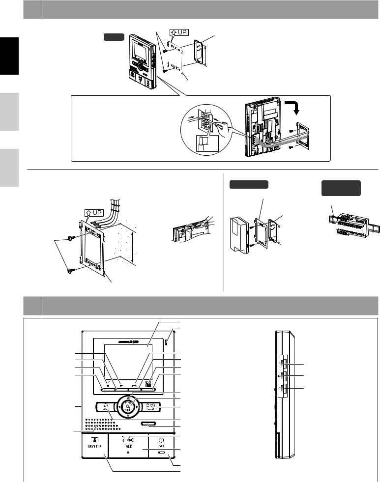
4 MOUNTING
Back wiring |
Mounting screws x 2 |
|
|
1-gang box |
|
|
JK-1MED |
|
|
|
|
|
|
83,5 mm |
|
|
(3-5/16") |
|
|
Mounting bracket |
Français
1. Press RELEASE button |
|
|
|
(to insert or remove the wire). |
1 |
|
|
2. Insert the cable into the terminal. |
2 |
||
|
Nederlands
 8mm (3/8")
Surface wiring
*When a 1-gang box is not mounted, the cable can be routed as surface wiring to the top or bottom of the unit. Cut a cable inlet on the upper part of the unit to allow passage of the wiring into the unit.
* To pass the cable through the back of the unit, cut out the cable inlet.
Wood |
|
mounting |
83,5 mm |
screws x 2 |
(3-5/16") |
Mounting bracket
5 NAMES
PS-1820 |
|
PS-1810DIN/ |
|
Mounting bracket |
PS-1820DIN |
|
|
|
|
|
Din rail |
|
1-gang box |
|
|
83,5 mm |
|
|
(3-5/16") |
|
JK-1MED
Play LED (red)
PLAY button
Record LED (red)
RECORD button
POWER switch
Speaker
Color LCD video monitor Microphone
Door release LED (red) DOOR RELEASE button
Menu LED (red) MENU button
PAN/TILT button ZOOM/WIDE button
ADJUST button
CALL button
Option button (*)
Transmit LED (red)
TALK button
Screen brightness control (0 10)
Receive volume control (0 10)
Chime tone volume (0 10)
OFF button |
(*) The option button controls connected option |
MONITOR button |
units such as turning lighting on and off and |
|
activation of added door releases. |
- 6 - |
|
 Loading...