


FK1260 0108 C
JF-2MED, JF-2HD
HANDS-FREE COLOR VIDEO INTERCOM INTERPHONE VIDEO COULEUR MAINS LIBRES HANDENVRIJE KLEURENVIDEOFONIE
JF-2MED |
JF-2HD |
Master monitor station |
Sub monitor station |
Moniteur maître |
Moniteur secondaire |
Monitor-hoofdpost |
Monitor-bijpost |
INSTALLATION & OPERATION MANUAL
MANUEL D’INSTALLATION ET D’UTILISATION
INSTALLATIEEN BEDIENINGSHANDLEIDING
- 1 -

English
Français
Nederlands
PRECAUTIONS
 General Prohibitions
  Prohibition to Dismantle the Unit
  Prohibition on Subjecting the Unit to Water
  General Precautions
 WARNING
(Negligence could result in death or serious injury.)
1. High voltage is present internally. Do not open the case. Electric shock could result.  2. Do not dismantle or alter the unit. Fire or electric shock could result.
3.Do not connect any non-specified power source to the +, - terminals, and do not install two power supplies in parallel to a single input. Fire or damage to the unit could result.

 4. Keep the unit away from water or any other liquid. Fire or electric shock could result.
5.Do not put any metal or flammable material into the unit through the openings. Fire or electric shock could result.
6.Do not use power supply with a voltage other than specified. Fire or electric shock could result.
7.Do not connect any terminal on the unit to AC power lines. Fire or electric shock could result.
 CAUTION
(Negligence could result in injury to people or damage to property.)
1.Do not install or make any wire terminations while power supply is plugged in. It can cause electrical shock or damage to the unit.
 2. Before turning on power, make sure wires are not crossed or shorted. If not, fire or electric shock could result.
 3. When mounting the unit on wall, install the unit in a convenient location, but not where it could be jarred or bumped. Injury could result.
 4. For power supply, use Aiphone power supply model specified with system. If nonspecified product is used, fire or malfunction could result.
5. Do not install the unit in any of the following locations. Fire, electric shock, or unit trouble could result.
Places under direct sunlight, or near heating equipment that varies in temperature.
Places subject to dust, oil, chemicals, etc.
Places subject to moisture and humidity extremes, such as bathroom, cellar, greenhouse, etc.
Places where the temperature is quite low, such as inside a refrigerated area or in front of air-conditioner.
Places subject to steam or smoke (near heating or cooking surfaces).
Where noise generating devices such as dimmer switches or inverter electrical appliances are close by.
6.Do not put anything on or cover the unit with cloth, etc. Fire or unit trouble could result.
7.Do not press on the LCD or subject it to a high impact. The LCD glass could be punctured and result in an injury.
8.If LCD is punctured, do not allow contact with the liquid crystal inside.
Inflammation could result.
If necessary, gargle your mouth and clean your eyes or skin with clear water for at least 15 minutes, and consult your doctor.
GENERAL PRECAUTIONS
1.Keep the unit more than 1 m away from radio or TV set.
2.This unit is for indoor use only. Do not use outdoors.
3.In areas where broadcasting station antennas are close by, the intercom system may be affected by radio frequency interference.
4.As to other manufacturer's devices (such as sensor, detectors, door releases) used with this system, comply with the Specifications and Warranty conditions that the manufacturers or venders present.
5.Keep the intercom wires more than 30 cm (12") away from AC 100~240 V lines. Noise and malfunction could result.
6.If the unit is down or does not operate properly, unplug the power supply or turn off the JF-2MED and JF-2HD Power switches.
7.The unit is for wall-mount use only. For desktop applications, use desk stand.
8.When wall-mounted, the unit may become dusty. Clean with a soft cloth.
9.The unit case may become a warm with use, but this is not a unit malfunction.
10.If a cellular phone is used close by, the unit may malfunction.
11.If must be noted in advance that the LCD panel, though manufactured with very high precision techniques, inevitably will have a very small portion of the picture elements steadily lit or not lit at all, which is not considered a unit malfunction.
12.Refrain from using the color monitor station in sunlit areas.
13.At night, due to reduced lighting on the object, the monitor sees more noise and the face becomes more difficult to see, but this is not malfunction.
14.Talk within 50 cm (20") or less from the unit. If you stand too far away, it may be difficult for the other person to hear the communication.
15.If there are loud noises around the unit (such as music playing or children crying), the sound may break up and be difficult to hear.
16.During communication, if you speak before the other person has finished talking, your voice may not be heard. Communication will proceed smoothly if you wait until the other person has finished before speaking.
17.At a gate or porch illuminated by fluorescent lamp, the picture may vary, but this is not a malfunction.
18.When outside temperature lowers sharply after rainfall, etc., the inside of the camera may fog up slightly, causing a blurry picture, but this is not a malfunction. Normal operation will be restored when moisture evaporates.
19.Due to the environmental sound around the unit, it may hinder smooth communication, but this is not a malfunction.
1 PACKAGE CONTENTS
JF-2MED or JF-2HD |
Mounting screws x 2 |
Wood mounting screws x 2 |
Option connector |
Release connector (JF-2MED only) |
Installation & Operation manual |
- 2 -
2 INSTALLATION
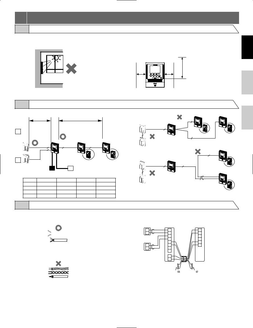
2-1 Mounting locations
1 Install the master monitor station and sub monitor station in places where the screens are not exposed to direct sunlight.
2 The master monitor station and sub |
3 Allow 15 cm (6") or more of vertical open space |
||
monitor station have switches on both |
from the center of the mounting bracket in order |
||
sides. |
to mount the master monitor station and sub |
||
Allow at least 5 cm (2") of open space on |
monitor station. |
||
either side. |
|
|
|
JF-2MED / JF-2HD |
3 |
||
2 |
|
||
+ 5 cm |
+ 15 cm |
||
+ 5 cm |
(6") |
||
(2") |
(2") |
||
|
|||
English
Français
2-2 Wiring method, Wiring distance
Wire the units from station-to-station (daisy-chained).
|
A |
|
B |
|
D1 |
|
|
|
|
JF-DA |
|
|
|
|
JF-DV |
|
|
JF-2HD |
JF-2HD |
JF-DVF |
|
JF-2MED |
||
|
|
|
|
|
|
2 |
4 |
4 |
|
|
2 |
|
|
|
D2 |
C |
D |
JF-2SD |
JF-2SD |
JF-DV |
PS-1820 |
SP IER-2 |
|
|
JF-DVF |
PS-1810DIN PS |
|
||
JF-D |
|
|
|
|
|
Ø 0,65 mm |
22AWG |
Ø 1,0 mm |
18AWG |
A |
50 m |
165' |
100 m |
330' |
B |
50 m |
165' |
100 m |
330' |
C |
5 m |
16' |
10 m |
33' |
D |
75 m |
245' |
150 m |
490' |
Incorrect method
|
|
|
JF-2HD |
JF-2HD |
|
JF-2MED |
4 |
|
|
JF-DA |
|
|
|
|
|
|
|
|
|
2 |
|
|
|
|
2 |
|
4 |
JF-2SD |
JF-2SD |
|
|
|
|
JF-2HD |
|
|
|
4 |
|
JF-DA |
JF-2MED |
|
|
|
|
|
|
|
|
2 |
|
4 |
|
|
|
|
|
|
JF-2SD |
2 |
|
|
|
JF-2HD |
|
|
8 |
|
|
|
|
|
|
|
|
|
|
|
JF-2SD |
2-3 Cable
1 Parallel or jacketed 2-conductor, mid-capacitance nonshielded cable is recommended. PVC jacket with PE (polyethylene) insulated conductors is recommended.
 (x2)
(x2)
2 Never use individual conductors, twisted pair cable or coaxial cable.
3 When using a cable with unused conductors, terminate both ends of the unused pair(s) with a 120 Ω resistor.
JF-DA |
|
JF-2MED |
JF-2HD |
|
A1 |
A1 |
B1 |
||
JF-DV |
||||
JF-DVF |
A2 |
A2 |
B2 |
|
|
|
A1 |
B1 |
|
JF-DA |
|
A2 |
B2 |
|
|
B1 |
+ |
||
JF-DV |
A1 |
B2 |
- |
|
JF-DVF |
A2 |
S |
|
|
JF-D |
|
S |
|
|
|
+ |
|
||
|
|
|
||
|
|
- |
|
120 120
Nederlands
- 3 -
English
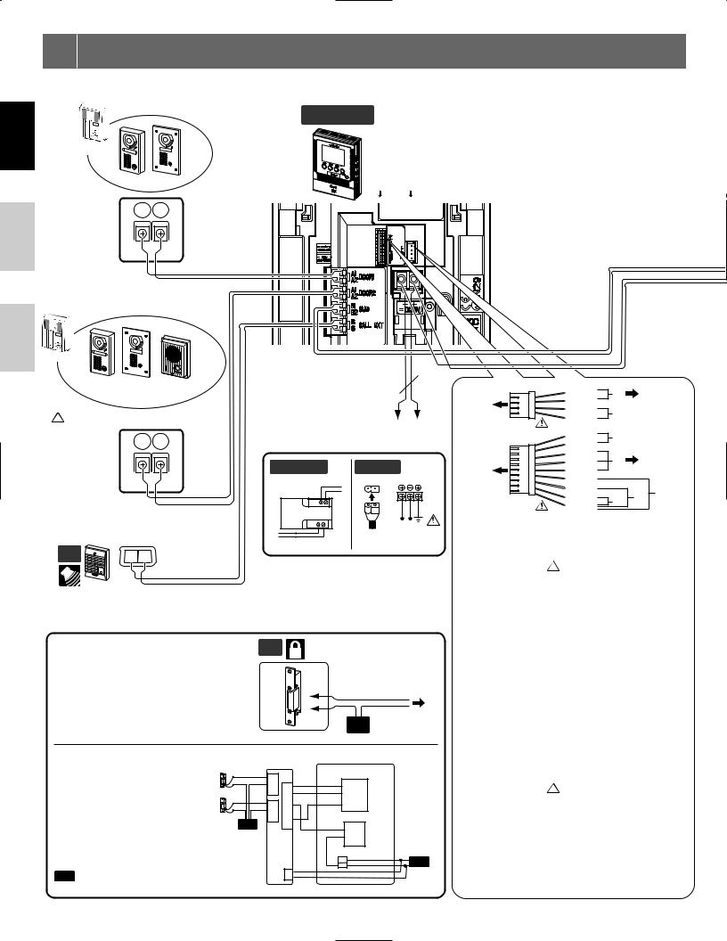
3 WIRING
Insert wires securely into each terminal as shown.
DOOR 1Video door station
JF-2MED Master monitor station
AIPHONE
JF-DA
JF-DA
JF-DV JF-DVF |
#2 #1 |
Français
Nederlands
A1 A2
2
NP
DOOR 2
AIPHONE
JF-DA
JF-DA
JF-DV JF-DVF JF-D
(Audio only)
 Setting is required. (Refer to section 7-7)
A1 A2
2
NP
Optional call extension speaker IER-2
OP |
1 |
E |
|
|
2 |
|
IER-2 |
NP |
|
|
Door release
P
2 - +
DC 18 V
Power supply +, - (DC 18 V)
PS-1810DIN PS-
230V AC N
|
L |
IN 230V~ 50/60Hz |
NL |
1A - + |
|
- |
100V - 240V |
+ |
|
18V DC 1 A |
50/60 Hz |
Release connector |
(BR) |
L |
[1] |
Door release |
|
|
(RD) |
L |
|||
#1 |
|
|
or |
||
(OG) |
SW |
[2] |
|
||
|
(YE) |
SW |
|
RY-3DL |
|
|
|
|
|
||
Option connector |
(BR) |
V + |
[3] |
|
|
(RD) |
V - |
|
|
||
|
|
|
|
||
|
(OG) |
b1 |
[4] |
RY-3DL |
|
#2 |
(YE) |
b2 |
|||
(GR) |
E |
|
|
|
|
|
(BL) |
PK |
|
|
|
|
(PR) |
FS |
|
[6] |
[5] |
|
(GY) |
KS |
[7] |
||
|
|
||||
|
(WH) |
E |
|
|
|
|
|
|
|
||
 To prevent shorts, be sure to cut unused lead wires at the bottom and insulate the ends.
Control external devices connected with release connector and option connector.
[1] Door release output  Setting is required. (Refer to section 7-8) (AC/DC 24 V, 0.5 A N/O dry closure contact)
Connect the brown and red wires from the release connector to the door release (or to the RY-3DL as shown in the wiring diagram).
[2]Options output
(AC/DC 24 V, 1.6 A N/O dry closure contact)
Door release EL-9S (AC 12 V, 0.35 A) or |
OP |
equivalent, requires a separate AC transformer. |
|
Run separate cables for audio/video and door |
|
release. |
|
Door release contact: AC/DC 24 V, 0.5 A |
|
(N/O dry closure contact L, L). |
|
2
NP
EL-9S PT
Optional selective door release |
|
RY-3DL |
JF-2MED |
|
adaptor RY-3DL |
EL-9S |
L1 |
|
Option connector |
Use RY-3DL when connecting |
|
|
||
|
b1 |
OG(b1) |
||
door release to 2 locations. |
EL-9S |
C1 |
||
L1 |
b2 |
YE(b2) |
||
|
|
L2 |
b3 |
GR(E) |
|
|
L |
||
|
|
C2 |
D1 |
Release connector |
|
|
L2 |
E |
|
|
|
PT |
D2 |
BR(L) |
|
|
|
|
|
|
|
|
|
RD(L) |
|
|
|
|
DC 18V |
|
|
|
|
+ |
|
|
|
+ |
– |
PT AC Transformer |
|
|
|
|
|
|
– |
|
|
[3]Video signal output
(NTSC, 1 Vp-p/75 Ω) Wiring distance: 3 m NOTES: When video signal is output to the external
equipment, it may be possible to hear the buzz noise from master station. Consult AIPHONE distributor.
[1][4] Door release-linked entrance output
[5]Press-to-talk setting input
If the blue and white wires are shorted, press-to-talk will not be operable.
[6]Foot switch input
Connect a commercially-available foot switch to the purple and white wires (N/O dry closure contact).
[7]External sensor input  Setting is required. (Refer to section 7-9)
|
N/O dry closure contact |
Input method |
External sensor input |
|
(start signal only detection method) |
Detection confirmation time |
100 mS or more |
Contact resistance |
During dry closure: Less than 700 Ω |
Terminal short current |
Less than 10 mA |
Voltage between terminals |
Less than DC 20 V |
(when open between terminals) |
|
|
|
- 4 -

JF-2HD Sub monitor station |
Option connector |
(BR) |
|
JF-2HD Sub monitor station |
|
|
|
|
|
|
|
(RD) |
|
|
|
|
(OG) SW |
[2] |
|
|
|
(YE) SW |
|
|
|
#3 |
|
|
|
|
(GR) |
|
|
|
|
|
(BL) PK |
|
|
|
|
(PR) FS |
[6] |
[5] |
#3 |
|
(GY) |
#3 |
|
|
(WH) E |
|
 To prevent shorts, be sure to cut unused lead wires at the bottom and insulate the ends.
4 |
4 |
- + |
- + |
NP: Non-polarized
P: Polarized
BR: Brown
RD: Red
OG: Orange
YE: Yellow
GR: Green
BL: Blue
PR: Purple
GY: Gray
WH: White
1st unit |
2nd unit |
|
ON |
1st unit 2nd unit |
3rd unit |
JF-2MED JF-2HD |
|
|
JF-2MED JF-2HD JF-2HD |
||
OFF |
ON |
|
|
OFF |
ON |
• Terminal setting (2nd unit) |
|
ON |
ON side when no 3rd unit is connected |
|
|
Setting changes are only required when a 3rd unit is connected. |
|
(leave in the factory settings) |
|
|
|
Put the switch in the ON position, and terminate the furthest sub station. |
|
|
|
|
|
If the terminal setting is incorrect, the monitor station and sub station will |
OFF |
OFF side when a 3rd unit is connected |
|
||
make a warning sound when they are operated. |
|
|
|
|
|
Further, the unit may not operate correctly or the video image may distort. |
After changing the setting, be sure to turn the power of the |
||||
|
|
monitor station on again. |
|
|
|
JF-2SD Sub station |
|
JF-2SD Sub station |
|
|
|
|
|
|
|
ON |
|
|
|
|
|
|
|
|
|
|
|
|
|
|
|
|
|
|
|
|
|
|
|
|
|
ON |
|
|
|
|
|
|
|
|
|
|
|
|
|
|
|
|
|
|
|
|
|
|
|
|
|
|
|
|
|
|
|
|
|
|
|
|
|
|
|
|
|
|
|
|
|
|
|
|
|
|
|
|
|
|
|
|
|
|
|
|
|
|
|
|
|
|
|
||
|
|
|
|
OFF |
|
|
|
|
|
|
|
|
|
|
|
|
|
|
|
|
|
|
|
|
|
|
|
|
|
OFF |
|
|
|
|
|
|
|
|
|
|
|
|
|
|
|
|
|
|
|
|
|
|
|
|
|
|
|
|
|
|
|
|
|
|
|
|
|
|
|
|
|
|
|
|
|
|
|
|
|
|
|
|
|
|
|
|
|
|
|
|
|
|
|
|
|
|
|
||
|
|
|
|
|
|
|
|
|
|
|
|
|
|
|
|
|
|
|
|
|
|
|
|
|
|
|
|
|
|
|
|
|
|
|
|
|
|
|
|
|
|
|
|
|
|
|
|||
|
|
|
|
1 |
|
2 |
3 |
4 |
5 |
|
|
6 |
|
|
|
|
|
|
1 |
2 |
3 |
|
4 |
5 |
|
|
6 |
|
|||||||||||||||||||||
SW1 |
|
|
|
|
|
SW5 1st unit |
2nd unit |
|
|
SW1 |
|
SW5 1st unit |
2nd unit |
3rd unit |
|
|
|||||||||||||||||||||||||||||||||
ON |
|
|
|
Yes |
|
|
|
JF-2MED |
JF-2SD |
|
|
ON |
|
|
|
Yes |
|
JF-2MED |
JF-2SD |
JF-2SD |
|
|
|||||||||||||||||||||||||||
|
|
|
|
|
|
|
|
|
|
|
|||||||||||||||||||||||||||||||||||||||
|
|
|
|
Call-in from door station 1 |
|
|
|
|
|
|
|
|
|
|
ON |
|
|
|
|
|
|
Call-in from door station 1 |
|
|
|
|
|
|
|
|
|
OFF |
|
|
ON |
|
|
||||||||||||
|
|
|
|
No |
|
|
|
|
|
|
|
|
|
|
|
|
|
|
|
|
|
|
|
|
No |
|
|
|
|
|
|
|
|
|
|
|
|
|
|
|
|
|
|
|
|
||||
SW2 |
|
|
|
|
|
|
|
|
|
|
|
|
|
|
|
|
|
|
|
|
|
SW2 |
|
|
|
|
|
|
|
|
|
|
|
|
|
|
|
|
|
|
|
|
|
||||||
ON |
|
|
|
Yes |
|
|
|
|
|
|
|
|
|
|
|
|
|
|
|
|
ON |
|
|
|
Yes |
|
|
|
|
|
|
|
|
|
|
|
|
|
|
|
|
|
|
|
|
||||
|
|
|
|
Call-in from door station 2 |
|
|
|
|
|
|
|
Not used. |
|
|
|
|
|
|
Call-in from door station 2 |
|
|
|
|
Not used. |
|
|
|
|
|
|
|
|
|
||||||||||||||||
|
|
|
|
No |
|
|
|
|
|
|
|
|
|
|
|
|
|
|
|
|
|
|
|
|
No |
|
|
|
|
|
|
|
|
|
|
|
|
|
|
|
|
|
|
|
|
||||
Optional long distance adaptor JBW-BA |
|
|
|
|
|
|
|
|
|
Use JBW-BA when the wiring distance between the |
|
JF-DA |
|
|
|
|
|
|
|
video door station and JF-2MED is within the distance |
|
|
|
|
|
|
|
|
|
|
JF-DV |
|
|
|
JBW-BA |
|
|
JF-2MED |
|
range shown in the table. |
|
JF-DVF |
|
|
+ - |
|
|
|
|
1. Use PE (polyethylene) insulated cable. |
|
|
A |
|
|
|
B |
|
|
Do not use PVC. |
|
|
2 |
|
|
|
2 |
|
|
|
|
A1 |
|
A1 |
B1 |
|
A1 |
||
|
|
|
|
|
|
||||
|
|
A2 |
NP |
1 |
A2 |
B2 |
P |
1 |
A2 |
|
|
|
|
+ |
+ |
||||
|
|
|
|
|
|
|
|
||
|
|
|
|
|
|
- |
2 |
|
- |
|
|
|
|
|
|
|
|
|
|
A |
Ø 1.0 mm |
18 AWG |
Ø 1.2 mm |
|
16 AWG |
|
P |
1 |
|
100~200 m |
330'~650' |
100~250 m |
330'~820' |
|
|
|
PS18 |
||
B (max.) |
50 m |
165' |
50 m |
165' |
C |
C (max.) |
50 m |
165' |
50 m |
165' |
English
Français
Nederlands
- 5 -
 Loading...