


Supplemental Operator’s Guide
for the Agilent 35670A Dynamic Signal Analyzer
By: |
David Forrest |
|
Seattle Sound and Vibration, inc. |
|
Print Date: December, 2000 |
|
ãSeattle Sound and Vibration, inc. 1996, 2000. |
|
All rights reserved. |
|
Agilent Part number 35670-90059 |
Special Permission |
Amoco Corporation and Agilent Technologies, Inc are granted |
|
full editing, duplication and distribution privileges. |
AGILENT 35670A
Supplemental Operator’s Guide
SECTION 1 : TURNING ON THE AGILENT 35670A .......................................................................................... |
1 |
SECTION 2 : MEASUREMENT STATE AFTER TURN-ON............................................................................... |
2 |
SECTION 3 : MEASURING WITH TRANSDUCERS........................................................................................... |
3 |
USING ICP-TYPE TRANSDUCERS WITH THE AGILENT 35670A .............................................................................. |
3 |
USING TRANSDUCERS WITH EXTERNAL PREAMPLIFIERS .......................................................................................... |
3 |
SPECIFYING TRANSDUCER SENSITIVITY AND UNITS ................................................................................................. |
4 |
SECTION 4 : MEASURING A SINGLE CHANNEL POWER SPECTRUM - DISPLACEMENT................... |
5 |
SELECTING SINGLE CHANNEL OPERATION ............................................................................................................... |
5 |
SETTING UP TRANSDUCER UNITS FOR DISPLACEMENT............................................................................................. |
5 |
SELECTING FREQUENCY SPAN .................................................................................................................................. |
5 |
QUANTIFYING POWER SPECTRUM RESULTS.............................................................................................................. |
7 |
SECTION 5 : IMPROVING MEASUREMENT RESULTS................................................................................... |
8 |
FREQUENCY ZOOMING TO INCREASE RESOLUTION................................................................................................... |
8 |
MAXIMIZING DYNAMIC RANGE ................................................................................................................................ |
8 |
AVERAGING TO REDUCE MEASUREMENT VARIANCE................................................................................................ |
9 |
SECTION 6 : MEASURING A SINGLE CHANNEL TIME WAVEFORM ...................................................... |
11 |
SELECTING SINGLE CHANNEL OPERATION ............................................................................................................. |
11 |
SELECTING TIME RECORD LENGTH......................................................................................................................... |
12 |
DISPLAYING TIME WAVEFORMS ............................................................................................................................. |
12 |
USING MANUAL ARM TO CAPTURE A SINGLE TIME WAVEFORM............................................................................ |
12 |
EVENT TRIGGERING................................................................................................................................................ |
13 |
QUANTIFYING TIME TRACE RESULTS ..................................................................................................................... |
14 |
SECTION 7 : MEASURING DUAL CHANNEL SPECTRA ............................................................................... |
15 |
PRESETTING THE ANALYZER................................................................................................................................... |
15 |
SELECTING DUAL CHANNEL OPERATION................................................................................................................ |
15 |
SELECTING FREQUENCY SPAN ................................................................................................................................ |
15 |
DISPLAYING DUAL-CHANNEL POWER SPECTRUM MEASUREMENTS....................................................................... |
15 |
USING MARKERS WITH DUAL CHANNEL MEASUREMENTS ..................................................................................... |
16 |
COUPLED MARKERS ............................................................................................................................................... |
17 |
COUPLED MARKERS WITH PEAK TRACKING ........................................................................................................... |
17 |
SECTION 8 : IMPROVING DUAL CHANNEL MEASUREMENT RESULTS................................................ |
18 |
MAXIMIZING DYNAMIC RANGE .............................................................................................................................. |
18 |
DUAL CHANNEL AVERAGING ................................................................................................................................. |
18 |
SECTION 9 : MEASURING DUAL CHANNEL TIME WAVEFORMS............................................................ |
20 |
SELECTING DUAL CHANNEL OPERATION................................................................................................................ |
20 |
SELECTING TIME RECORD LENGTH......................................................................................................................... |
20 |
DISPLAYING DUAL TIME WAVEFORMS................................................................................................................... |
20 |
ARMING DUAL CHANNEL TIME MEASUREMENTS................................................................................................... |
21 |
TRIGGERING A DUAL-CHANNEL TIME MEASUREMENT........................................................................................... |
21 |
TRIGGER DELAY ..................................................................................................................................................... |
22 |
USING MARKERS WITH DUAL CHANNEL TIME MEASUREMENTS ............................................................................ |
23 |
SECTION 10 : MEASURING DUAL CHANNEL SPECTRA AND TIME WAVEFORMS.......................... |
23 |
AGILENT 35670A
Supplemental Operator’s Guide
SECTION 11 : MODAL TESTING USING A HAMMER AND ACCELEROMETER................................. |
25 |
SETTING UP THE TRANSDUCER PARAMETERS......................................................................................................... |
25 |
SETTING UP INPUT RANGE...................................................................................................................................... |
26 |
CHOOSING A PRELIMINARY FREQUENCY SPAN ....................................................................................................... |
26 |
SPECIFYING TRIGGER PARAMETERS ....................................................................................................................... |
26 |
SETTING UP TIME DISPLAYS................................................................................................................................... |
27 |
USING FORCE/RESPONSE WINDOWS ....................................................................................................................... |
28 |
DISPLAYING HAMMER TEST RESULTS .................................................................................................................... |
29 |
AVERAGING ............................................................................................................................................................ |
29 |
CHANGING FREQUENCY SPAN ................................................................................................................................ |
31 |
SECTION 12 : HAMMER TEST SETUP WITHOUT A FORCE TRANSDUCER........................................ |
32 |
SETTING UP THE HAMMER TEST WITHOUT A FORCE TRANSDUCER ....................................................................... |
32 |
SECTION 13 : ORDER DOMAIN RESULTS IN LIST MODE........................................................................ |
33 |
SECTION 14 : COMPARING TWO-CHANNEL REAL-TIME SPECTRA WITH RECALLED DATA.... |
35 |
SELECTING MEASUREMENT PARAMETERS.............................................................................................................. |
35 |
DISPLAYING DUAL-CHANNEL SPECTRA COMPARED WITH RECALLED DATA ......................................................... |
35 |
RECALLING THE SPECTRA FROM DISK .................................................................................................................... |
36 |
RECALLING THE SPECTRA FROM NON-VOLATILE RAM ......................................................................................... |
36 |
SCALING THE DISPLAYS.......................................................................................................................................... |
37 |
USING MARKERS TO COMPARE............................................................................................................................... |
38 |
SECTION 15 : WATERFALL SPECTRA AT TIME INTERVALS ................................................................ |
39 |
SELECTING SINGLE CHANNEL OPERATION ............................................................................................................. |
39 |
SELECTING MEASUREMENT PARAMETERS.............................................................................................................. |
39 |
SETTING UP THE WATERFALL DISPLAY .................................................................................................................. |
39 |
SETTING UP TIME STEP ARM .................................................................................................................................. |
40 |
USING SLICE MARKERS WITH WATERFALL DATA .................................................................................................. |
40 |
COLLECTING A SPECIFIED NUMBER OF SPECTRA DURING A TIME INTERVAL ......................................................... |
41 |
SECTION 16 : WATERFALL SPECTRA AT RPM INTERVALS.................................................................. |
42 |
SETTING UP THE TACHOMETER .............................................................................................................................. |
42 |
SPECIFYING THE START RPM ................................................................................................................................. |
42 |
COLLECTING A SPECIFIED NUMBER OF SPECTRA DURING AN RPM INTERVAL....................................................... |
42 |
STARTING AND PAUSING A MEASUREMENT............................................................................................................ |
43 |
SCALING THE DISPLAY............................................................................................................................................ |
43 |
SECTION 17 : 2-CHANNEL ABSOLUTE AND DIFFERENTIAL AMPLITUDE MEASUREMENT ....... |
45 |
ACCELEROMETER POLARITY................................................................................................................................... |
45 |
MEASURING AMPLITUDES, DIFFERENTIAL AMPLITUDE, AND PHASE...................................................................... |
46 |
USING A MATH FUNCTION TO MEASURE DIFFERENTIAL MOTION .......................................................................... |
47 |
SECTION 18 : MEASURING FREQUENCY RESPONSE WITH THE AGILENT 35670A ........................ |
50 |
MEASURING FREQUENCY RESPONSE USING IMPACT EXCITATION.......................................................................... |
50 |
MEASURING FREQUENCY RESPONSE USING BROADBAND EXCITATION ................................................................. |
50 |
VIEWING FREQUENCY RESPONSE RESULTS WITH A NYQUIST DIAGRAM ................................................................ |
53 |
VIEWING RESULTS USING REAL AND IMAGINARY TRACES .................................................................................... |
54 |
ASSESSING MEASUREMENT QUALITY..................................................................................................................... |
55 |
SECTION 19 : TWO SPECTRAL TRACES SHOWING MILS AND IPS WHILE EU IS G........................ |
56 |
SECTION 20 : PEAK HOLD DURING A MACHINE RUN-UP AND COAST-DOWN................................ |
58 |
AGILENT 35670A
Supplemental Operator’s Guide
SECTION 21 : USING AN EXTERNAL TRIGGER FOR TIME AVERAGING ........................................... |
60 |
SPECIFY USER LEVELS FOR TRIGGERING ................................................................................................................ |
60 |
CHARACTERIZING THE EXTERNAL TRIGGER ........................................................................................................... |
60 |
SETTING UP EXTERNAL TRIGGER ........................................................................................................................... |
61 |
MEASURING TIME AVERAGED SPECTRUMS WITH EXTERNAL TRIGGERING............................................................. |
62 |
SECTION 22 : SAVING TRACE DATA TO A 3.5” DISK OR NON-VOLATILE RAM .............................. |
63 |
SAVING TRACE TO 3.5” DISK.................................................................................................................................. |
63 |
CONFIRMING CONTENTS OF 3.5” DISK FILE............................................................................................................ |
63 |
SAVING TRACE TO NON-VOLATILE RAM (NV-RAM)........................................................................................... |
64 |
CONFIRMING CONTENTS OF NV-RAM ................................................................................................................... |
64 |
SECTION 23 : RECALLING TRACE DATA FROM 3.5” DISK OR NON-VOLATILE MEMORY.......... |
65 |
RECALL TRACE FROM 3.5” DISK ............................................................................................................................ |
65 |
RECALL TRACE DATA FROM NON-VOLATILE RAM (NV-RAM)............................................................................ |
65 |
SECTION 24 : PLOTTING AND PRINTING TRACE DATA ......................................................................... |
67 |
GENERATING OUTPUT WITH THE AGILENT 35670A............................................................................................. |
67 |
PLOTTING THE DISPLAY.......................................................................................................................................... |
67 |
PRINTING THE DISPLAY........................................................................................................................................... |
68 |
SECTION 25 : IMPORTING PLOTS INTO MICROSOFT WORD................................................................ |
69 |
DETERMINING IF MS WORD HAS HP-GL GRAPHICS IMPORT FILTER..................................................................... |
69 |
INSTALLING THE MS WORD HP-GL GRAPHICS IMPORT FILTER............................................................................. |
69 |
PLOT TO A FILE USING THE AGILENT 35670A ..................................................................................................... |
70 |
INSERTING PICTURE OF AN HP-GL PLOT FILE INTO A MS WORD DOCUMENT. ...................................................... |
70 |
SECTION 26 : RUNNING A SINGLE CALIBRATION TEST ON COMMAND .......................................... |
71 |
SECTION 27 : RETURNING THE AGILENT 35670A TO A PRESET CONDITION.................................. |
71 |
SECTION 28 : PRECAUTIONS TO PREVENT LOSS OF DATA .................................................................. |
71 |
SECTION 29 : TRANSDUCER UNIT CONVERSION WITH THE AGILENT 35670A............................... |
72 |
MEASURING ACCELERATION, DISPLAYING DISPLACEMENT ................................................................................... |
72 |
MATH FUNCTIONS AND XDCR UNIT CONVERT................................................................................................. |
73 |
CONVERTING FREQUENCY RESPONSE UNITS TO COMPLIANCE ............................................................................... |
73 |
SECTION 30 : USING THE AGILENT DEMO UNIT WITH THE AGILENT 35670A................................ |
75 |
AGILENT 35670A
Supplemental Operator’s Guide
Section 1 : Turning On the AGILENT 35670A
The entire turn-on procedure for the AGILENT 35670A takes 40 seconds. In that time the analyzer completes a hardware self-test, boots its operating system, completes a front end self-calibration and autoranges all input channels. The default measurement state of the analyzer is a two-channel FFT measurement with a span of 51.2 kHz, front ends autoranging, input low floating, and DC coupled, averaging OFF and with a power spectrum display.
|
|
|
|
|
FFT |
|
|
|
|
|
ANALYSIS |
||
A: CH1 Pwr Spec |
X:0 |
Hz |
Y:40.9385 uVrms |
OCTAVE |
|
|
10 |
|
|
|
ANALYSIS |
||
mVrms |
|
|
|
|
|
|
|
|
|
|
ORDER |
|
|
|
|
|
|
ANALYSIS |
||
|
|
|
|
SWEPT |
|
|
LogMag |
|
|
|
SINE |
|
|
|
|
|
|
|
|
|
6 |
|
|
|
CORRELATN |
||
decades |
|
|
|
|||
|
|
|
ANALYSIS |
|||
|
|
|
|
|||
|
|
|
|
HISTOGRAM |
||
|
|
|
|
/ TIME |
|
|
|
|
|
|
CHANNELS |
||
|
|
|
|
1 |
2 |
4 |
|
|
|
|
REF CHANS |
||
|
|
|
|
1 |
1,3 |
|
10 |
|
|
|
TIME |
|
|
nVrms |
|
|
|
CAPTURE |
||
0Hz |
|
|
|
51.2kHz |
|
|
Typical Display After Turn-on Sequence
1

AGILENT 35670A
Supplemental Operator’s Guide
Section 2 : Measurement State After Turn-on
Inst Mode |
FFT |
|
|
Channels |
2 |
|
|
Measurement Source |
INPUT |
|
|
||
Meas Data |
Data A |
PWR SPEC1 |
Data B |
PWR SPEC2 |
||
|
Data C |
TIME1 |
Data D |
TIME2 |
||
Trac Coord Coord A |
MAG-LOG |
Coord B |
MAG-LOG |
|||
|
Coord C |
REAL |
Coord D |
REAL |
|
|
Freq |
Start |
0 Hz |
Stop |
51.2 kHz |
||
|
Center |
25.6 kHz |
Span |
51.2 kHz |
||
|
Rec Len |
7.8125 ms |
Resoltn |
400 |
|
|
Window |
CH1 Type |
FLATTOP |
BW |
488.88 Hz |
||
|
CH2 Type |
FLATTOP |
BW |
488.88 Hz |
||
|
CH3 Type |
FLATTOP |
BW |
488.88 Hz |
||
|
CH4 Type |
FLATTOP |
BW |
488.88 Hz |
||
Avg |
Status |
OFF |
|
Type |
RMS |
|
|
Number |
10 |
|
Overlap |
0 % |
|
|
Fast Avg |
OFF |
|
Update |
5 |
|
|
Rept Avg |
FREEZE |
Ovld Rej |
OFF |
|
|
Trigger |
Type |
FREE-RUN |
Level |
0 V |
|
|
|
Slope |
POSITIVE |
|
|
|
|
|
Ext Lvl |
1.48 V |
|
|
|
|
|
Ext Fltr |
OFF |
|
|
|
|
|
CH1 Dlay |
0 s |
|
CH2 Dlay |
0 s |
|
|
CH3 Dlay |
0 s |
|
CH4 Dlay |
0 s |
|
|
Arm |
IMMEDIATE |
Strt RPM |
600 |
rpm |
|
|
RPM Step |
60 rpm |
Time Stp |
500 |
ms |
|
|
Wtrfall |
15 |
|
RPM Dir |
UP |
|
Source |
Status |
OFF |
|
|
|
|
|
Level |
0 Vpk |
DC Offst |
0 V |
|
|
|
Type |
SINUSOID |
Sine Frq |
10.24 kHz |
||
|
Arb Fltr |
OFF |
|
Arb Reg |
D1 |
|
|
Arb Rept |
ON |
|
|
|
|
Input |
CHANNEL 1 |
|
CHANNEL 2 |
CHANNEL |
3 |
CHANNEL 4 |
Status |
ON |
|
ON |
OFF |
|
OFF |
Range |
3.9858 mVp |
3.9858 mVp |
3.9858 mVp |
3.9858 mVp |
||
Auto Rng |
OFF |
|
OFF |
OFF |
|
OFF |
Coupling |
DC |
|
DC |
DC |
|
DC |
InputLow |
FLOAT |
|
FLOAT |
FLOAT |
|
FLOAT |
AliasFlt |
ON |
|
ON |
ON |
|
ON |
A WtFltr |
OFF |
|
OFF |
OFF |
|
OFF |
ICP |
OFF |
|
OFF |
OFF |
|
OFF |
EngrUnit |
OFF |
|
OFF |
OFF |
|
OFF |
EU Label |
USER |
|
USER |
USER |
|
USER |
EU Mult |
1 V/EU |
|
1 V/EU |
1 V/EU |
|
1 V/EU |
--- TACHOMETER --- |
|
|
|
|
|
|
Puls/Rev 1 |
|
|
|
|
|
|
Level |
0 V |
|
|
|
|
|
Range |
LOW |
|
|
|
|
|
Slope |
POSITIVE |
|
|
|
|
|
Holdoff |
0 s |
|
|
|
|
|
2

AGILENT 35670A
Supplemental Operator’s Guide
Section 3 : Measuring with Transducers
The AGILENT 35670A can be used with a broad range of transducers. Transducers can use an external preamplifier to convert the raw signal into a voltage that is compatible with the AGILENT 35670A. Some transducers have internal circuitry which provides preamplification, however these internal circuits must be powered externally. The AGILENT 35670A can provide the necessary constant-current supply for transducers that are of type ICP, Isotron, Piezotron, DelaTron, Low Impedance, etc.
Using ICP-Type Transducers with the AGILENT 35670A
To set up Channel 1 for an ICP-type transducer:
•Press the [Input] hardkey
• |
Press [FRONT END CH1 SETUP] softkey (F7). |
• |
Press [ICP SUPLY ON OFF] softkey (F8) until ON is highlighted. |
Note that the analyzer automatically switches the front end to AC Coupling in order to reject the large DC signal that is generated by the constant-current supply.
To set up Channel 2 for an ICP transducer:
•Press the [Input] hardkey
• |
Press [CHANNEL 1 |
2 3 |
4] softkey (F1) until 2 is highlighted. |
• |
Press [FRONT END |
CH2 |
SETUP] softkey (F7). |
•Press [ICP SUPLY ON OFF] softkey (F8) until ON is highlighted.
For AGILENT 35670A analyzers with four channels, these same procedures can be repeated for Channels 3 and 4.
Using Transducers with External Preamplifiers
No special front end setup is required to use transducers with external preamplifiers except if the preamplifier’s DC component is too high, resulting in a loss of dynamic range. This can be easily minimized by switching to AC coupling as follows:
•Press the [Input] hardkey
• |
Press [CHANNEL 1 2 3 4] softkey (F1) until 1 is highlighted. |
|
• |
Press |
[FRONT END CH1 SETUP] softkey (F7). |
• |
Press |
[COUPLING AC DC] softkey (F5) until AC is highlighted. |
A transducer with an external preamplifier will convert mechanical units (EU) to volts. Care must be taken to observe gain settings on the external preamplifier, because these gain settings directly affect the resulting transducer sensitivity.
3

AGILENT 35670A
Supplemental Operator’s Guide
For example, if an accelerometer has am internal sensitivity of 25 pC/g, and a charge amplifier has a gain setting of 10 mV/pC, then the resulting transducer sensitivity is 250 mV/g. However is the gain setting on the charge amplifier is changed to 1 mV/pC, then the resulting sensitivity would then be 25 mV/g.
Specifying Transducer Sensitivity and Units
The AGILENT 35670A provides the ability to convert electrical signals into Engineering Units. Units can be specified as either conventional units or User units. Conventional units of motion available are:
acceleration: |
g, m/s^2, inch/s^2 |
velocity: |
m/s, inch/s |
displacement: |
m, inch, mil |
force: |
N, lb., dyne |
To set up transducer properties for an accelerometer attached to Channel 2 with a sensitivity of 9.7 pC/g, follow these steps:
•Press [Input] hardkey.
• |
Press [CHANNEL 1 2 3 4] softkey (F1) until 2 is highlighted. |
• |
Press [XDCR UNIT CH2 SETUP] softkey (F8) |
• |
Press the [XDCR SENSITVTY] softkey (F6). |
•Enter 9.7, then press the [mV/EU] softkey (F2).
• |
Toggle the [XDCR UNIT ON OFF] softkey (F4) until ON is highlighted. |
• |
Press the [XDCR UNIT LABEL] softkey (F7). |
•Select the [g] softkey (F2).
Likewise if a force transducer is attached to Channel 1 with a sensitivity of 12.2 mV/lb., do the following:
•Press [Input] hardkey.
• |
Press [CHANNEL 1 2 3 4] softkey (F1) until 1 is highlighted. |
• |
Press [XDCR UNIT CH1 SETUP] softkey (F8) |
• |
Press the [XDCR SENSITVTY] softkey (F6). |
•Enter 12.2, then press the [mV/EU] softkey (F2).
• |
Toggle the [XDCR UNIT ON OFF] softkey (F4) until ON is highlighted. |
• |
Press the [XDCR UNIT LABEL] softkey (F7). |
•Press the [MORE CHOICES] softkey (F9).
•Select the [ lb ] softkey (F6).
4

AGILENT 35670A
Supplemental Operator’s Guide
Section 4 : Measuring a Single Channel Power Spectrum - Displacement
This section contains procedures for setting up and measuring a single channel power spectrum of displacement using an AGILENT 35670A Dynamic Signal Analyzer. Included are steps to select single channel operation, set up transducer parameters, frequency span, choose input range, select windowing, and turn on averaging in order to improve measurement accuracy. Instructions will also be presented to set up trace coordinates and trace scaling.
Selecting Single Channel Operation
Specify the single-channel instrument mode to measure one signal. However it should be noted that it is acceptable to measure a single channel in the default twochannel instrument mode and simply ignore the second channel. Nevertheless instructions will be given here to measure in single channel mode.
To measure a single-channel spectrum, turn on the AGILENT 35670A and then:
•Press the [Inst Mode] hardkey
•Press [CHANNELS 1 2 4 ] softkey (F7) until 1 is highlighted.
Setting Up Transducer Units for Displacement
To measure power spectrums using a displacement transducer with a sensitivity of 200 mV/mil, follow these steps:
•Press the [Input] hardkey.
•Enter 800 and then press the [Hz] softkey (F2).
Any frequency below 51.2 kHz may of course be entered, however the analyzer will select the lowest span that contains the desired frequency. For example, if 1200 Hz is entered, the analyzer is switched to a span of 1600 Hz.
Selecting Frequency Span
The default frequency span after turn-on is 51.2 kHz, which is usually too high for most transducer measurements. To reduce the span to 800 Hz, perform the following steps:
•Press the [Freq] hardkey.
•Enter 800 and then press the [Hz] softkey (F2).
5

AGILENT 35670A
Supplemental Operator’s Guide
Any frequency below 51.2 kHz may of course be entered, however the analyzer will select the lowest span that contains the desired frequency. For example, if 1200 Hz is entered, the analyzer is switched to a span of 1600 Hz.
Frequency Spans Available
for the AGILENT 35670A
102.4 |
kHz * |
100 Hz |
|
51.2 |
kHz |
50 Hz |
|
25.6 |
kHz |
25 Hz |
|
12.8 |
kHz |
12.5 Hz |
|
6.4 |
kHz |
6.25 Hz |
|
3.2 |
kHz |
3.125 Hz |
|
1.6 |
kHz |
1.5625 Hz |
|
800 |
Hz |
0.78125 Hz |
|
400 |
Hz |
0.390625 |
|
200 |
Hz |
0.1953125 Hz |
|
* Available in single-channel mode when anti-alias filter is turned off. To begin data acquisition,
•Press the [Start] hardkey.
To automatically scale the display to fit the data,
•Press the [Scale] hardkey.
•Toggle the [AUTOSCALE ON OFF] softkey (F1) until ON is highlighted.
6
AGILENT 35670A
Supplemental Operator’s Guide
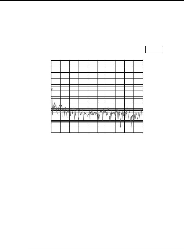
Input |
CH1 |
Rng: 501.7819 mVpk |
CH2 |
Rng: 631.706 mVpk |
|
CH3 |
Rng: 2.5149 Vpk |
CH4 |
Rng: 2.5149 Vpk |
Date: 10-02-96 Time: 08:42:00 PM |
|
||
A: CH1 Pwr Spec |
X:160 |
Hz |
Y:169.558 mVrms |
1 |
|
|
|
Vrms |
|
|
|
LogMag |
|
|
|
6 |
|
|
|
decades |
|
|
|
1 |
|
|
|
uVrms |
|
|
|
0Hz |
|
|
800Hz |
Quantifying Power Spectrum Results
Use the marker knob to read the amplitude at any measured frequency. Rotate the knob on the AGILENT 35670A front panel until the marker indicator (the small diamond following the spectral trace) is placed at the frequency of interest. The frequency and amplitude at this bin is presented as X and Y values at the top of the trace. Units of [Hz] and [Vrms] or [grms] identify the results.
Special marker features such as peak tracking can speed analysis. To always track the peak amplitude and frequency, follow these steps:
•Press the [Marker] hardkey.
•Press [PEAK TRK ON OFF] softkey (F6) until ON is highlighted.
The frequency and amplitude of the peak bin in every trace will be determined and displayed.
7

AGILENT 35670A
Supplemental Operator’s Guide
Section 5 : Improving Measurement Results
Frequency Zooming to Increase Resolution
The AGILENT 35670A has the ability to zoom in on a signal to show detail with very fine resolution. After choosing a center frequency, it is possible to decrease the span and therefore increase the resolution all the way down to 61 Hz. To zoom in on a signal, move the marker to the desired center frequency, then:
•Press the [Freq] hardkey.
•Press the [CENTER] softkey (F2).
•Press the [Mkr Value] hardkey.
To set a new, lower span,
•Press the [Freq] hardkey.
•Press the [Down Arrow] hardkey
•Press the yellow [Start] hardkey to begin the zoomed measurement.
To return to baseband measurements,
•Press the [Freq] hardkey.
•Press the [ZERO START] softkey (F5).
Maximizing Dynamic Range
The default setting for input range is CH1 AUTO RANGE. For steady-state signals this works well because the front end will find the input range that just exceeds the signal level, and therefore maximize the dynamic range of the measurement. When a front end is set up to autorange and the signal either overloads or becomes too faint for the current range setting, the analyzer automatically searches for a new range and then re-starts the measurement. To select CH1 AUTO RANGE:
• Select the [CH1 AUTO RANGE] softkey (F6)
If a signal is not steady, but has periods of high and low levels, then CH1 AUTO RANGE may not set the front end at the most useful range. Instead, try CH1 AUTO UP ONLY. This causes the input range to ratchet up when an overload is detected, however when the signal is quiet, the front end range is not reduced. This prevents an overload if another high level signal is expected. CH1 AUTO UP ONLY works well with transient signals such as those expected during impact testing. To set up this condition:
•Press the [Input] hardkey.
•Select the [CH1 AUTO UP ONLY] softkey (F5).
8

AGILENT 35670A
Supplemental Operator’s Guide
If continuous real-time measurements over a long duration are required, and absolutely no overload conditions are desired, then a fixed input range can be set that is greater than any signal expected. During periods of low signal level, dynamic range will not be optimal, however the entire measurement can be completed without overloads. To set up a fixed range of 1 volt:
•Press the [Input] hardkey.
•Select the [CHANNEL 1 RANGE] softkey (F3), enter 1, then press the [Vpk] softkey (F1).
If engineering units are turned on ([XDCR UNIT ON OFF]) then the range can be specified in EU. For example, if an accelerometer is connected to channel 1 with XDCR UNIT turned on and XDCR UNIT LABEL specified as [g], then the input range can be specified as 4 “g” as per the following:
•Press the [Input] hardkey.
• Select the [CHANNEL 1 RANGE] softkey (F3)
•Enter 4, then press the [EU] softkey (F8).
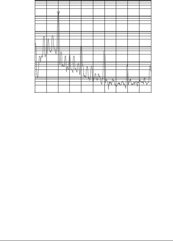
Averaging to Reduce Measurement Variance
Spectral measurements of steady signals give results which have a statistical variation over time. Averaging several results will help reduce this variation. The AGILENT 35670A has several averaging techniques available. For general spectrum measurements, RMS or power averaging is commonly used. To average a series of ten spectrum measurements using RMS averaging, follow these steps:
•Press the [Avg] hardkey.
•Press the [NUMBER AVERAGES] softkey (F2), enter 10, then press the
[ENTER] softkey (F1).
•Press the [AVERAGE TYPE] softkey (F3)
•Press the [RMS] softkey (F1)
•Press the [Avg] hardkey.
•Turn on averaging by pressing the [AVERAGE ON OFF] softkey (F1) until ON is highlighted.
9
AGILENT 35670A
Supplemental Operator’s Guide
Systm Util |
Date: 10-02-96 |
|
|
|
|
|
|
Time: 08:40 PM |
|
|
|
||
Date: 01-02-04 Time: 12:44:00 PM |
|
|
|
|||
A: CH1 Pwr Spec |
X:160 |
Hz |
|
|
Y:174.015 mVrms |
|
1 |
|
|
|
|
|
|
Vrms |
|
|
|
|
|
|
LogMag |
|
|
|
|
|
|
6 |
|
|
|
|
|
|
decades |
|
|
|
|
|
|
1 |
|
|
|
|
|
|
uVrms |
0Hz |
|
|
AVG: |
5 |
800Hz |
|
|
|
||||
•
10

AGILENT 35670A
Supplemental Operator’s Guide
Section 6 : Measuring a Single Channel Time Waveform
This section contains procedures for setting up and measuring a single channel time waveform using an AGILENT 35670A Dynamic Signal Analyzer. Included are steps to select single channel operation, set up the trace time length, and set up triggering to capture a transient event. Instructions will also be presented to scale the time trace.
Selecting Single Channel Operation
To measure a single-channel time waveform, turn on the AGILENT 35670A and then:
•Press the [Inst Mode] hardkey
•Press [CHANNELS 1 2 4 ] softkey (F7) until 1 is highlighted.
Note: if the AGILENT 35670A was already turned on and in an unknown state, then preset the analyzer by doing the following:
•Press the green [Preset] hardkey
•Press [DO PRESET] softkey (F1).
Then set the instrument mode to single channel as above.
Time Record Length in Seconds vs. Resolution
Span - Hz |
100 lines |
200 lines |
400 lines |
800 lines |
1600 lines |
|
51200 Hz |
0.001953 s |
0.003906 s |
0.007813 s |
0.015625 s |
0.03125 s |
|
25600 Hz |
0.003906 s |
0.007813 s |
0.015625 s |
0.03125 s |
0.0625 s |
|
12800 Hz |
0.007813 s |
0.015625 s |
0.03125 s |
0.0625 s |
0.125 s |
|
6400 |
Hz |
0.015625 s |
0.03125 s |
0.0625 s |
0.125 s |
0.25 s |
3200 |
Hz |
0.03125 s |
0.0625 s |
0.125 s |
0.25 s |
0.5 s |
1600 |
Hz |
0.0625 s |
0.125 s |
0.25 s |
0.5 s |
1 s |
800 Hz |
0.125 s |
0.25 s |
0.5 s |
1 s |
2 s |
|
400 Hz |
0.25 s |
0.5 s |
1 s |
2 s |
4 s |
|
200 Hz |
0.5 s |
1 s |
2 s |
4 s |
8 s |
|
100 Hz |
1 s |
2 s |
4 s |
8 s |
16 s |
|
50 Hz |
2 s |
4 s |
8 s |
16 s |
32 s |
|
25 Hz |
4 s |
8 s |
16 s |
32 s |
64 s |
|
12.5 |
Hz |
8 s |
16 s |
32 s |
64 s |
128 s |
6.25 |
Hz |
16 s |
32 s |
64 s |
128 s |
256 s |
3.125 |
Hz |
32 s |
64 s |
128 s |
256 s |
512 s |
1.5625 |
Hz |
64 s |
128 s |
256 s |
512 s |
1024 s |
0.78125 |
Hz |
128 s |
256 s |
512 s |
1024 s |
2048 s |
0.390625 |
Hz |
256 s |
512 s |
1024 s |
2048 s |
4096 s |
0.1953125 |
Hz |
512 s |
1024 s |
2048 s |
4096 s |
8192 s |
11

AGILENT 35670A
Supplemental Operator’s Guide
Selecting Time Record Length
The default time record length at a frequency span of 51.2 kHz is only 7.8 ms, which is usually not enough time to capture a mechanical event or observe a transducer’s time domain signal. To increase the time record length to 0.25 s, perform the following steps:
•Press the [Freq] hardkey
•Press the [RECORD LENGTH] softkey (F8)
•Enter 0.25 and then press the [S] softkey (F1)
The analyzer selects a new frequency span of 1.6 kHz, which at the default resolution of 400 lines, takes 0.25 seconds to capture. The following table outlines the time record lengths for all possible frequency spans and resolutions:
Displaying Time Waveforms
Time waveforms are displayed in a time trace. To set up the analyzer to display a single time trace of channel 1, follow these steps:
•Press the [Disp Format] hardkey.
•Press the [SINGLE] softkey (F1)
•Press the [Active Trace] hardkey.
•Press the [A] softkey (F1)
•Press the [Meas Data] hardkey.
• Press the [CHANNEL 1 2 3 4] softkey (F1) until 1 is highlighted.
•Press the [TIME CHANNEL 1] softkey (F5)
•Press the [Scale] hardkey.
•Toggle the [AUTOSCALE ON OFF] softkey (F1) until ON is highlighted.
Using Manual Arm to Capture a Single Time Waveform
Often it is desirable to observe just one time waveform in detail. To acquire just one record length at a time, follow these instructions:
•Press the [Trigger] hardkey.
• Select the [ARM SETUP] softkey (F7)
•Select the [MANUAL ARM] softkey (F2)
•Press the yellow [Start] hardkey to begin the measurement.
•Press the [Trigger] hardkey again.
Then to arm a single time record,
•Press the [ARM] softkey (F9)
One time record will be captured and displayed. To capture another time record,
12

AGILENT 35670A
Supplemental Operator’s Guide
•Press the [ARM] softkey (F9) again.
Event Triggering
The AGILENT 35670A has the ability to trigger the acquisition of a time waveform based on the slope and level of the measured signal. To set up triggering properly, the polarity of the measured pulse must be known in advance: will the event start with a negative slope or positive slope? Will the event be mostly positive or mostly negative? Use trial measurements to determine polarity if unknown.
Proper triggering is also affected by the input range. Fortunately the AGILENT 35670A has the ability to set the trigger point to be a percentage of the input range, so even with CH1 AUTO UP ONLY, successful triggering should be possible automatically.
To specify trigger parameters for a “positive” event on channel 1 where the trigger point should have a positive slope, follow these steps:
•Press the [Trigger] hardkey.
• |
Press the |
[CHANNEL 1 2 3 4] softkey (F3) until 1 is highlighted. |
• |
Press the |
[TRIGGER SETUP] softkey (F6) |
• |
Press the |
[CHANNEL LEVEL] softkey (F1) |
•Enter 5 then press the [PERCENT (%)] softkey (F4)
•Press the [SLOPE POS NEG] softkey (F5) until POS is highlighted.
Use pre-triggering to acquire some data before the trigger point. To set up a 0.01s pre-trigger condition, follow these steps:
•Press the [Trigger] hardkey.
• |
Press the |
[TRIGGER SETUP] softkey (F6) |
• |
Press the |
[ALL CHANNELS] softkey (F8) |
• |
Press the |
[CHANNEL * DELAY] softkey (F9) |
•Enter -.01 then press the [S] softkey (F1)
To start the data acquisition,
•Press the yellow [Start] hardkey.
The analyzer should show in highlighted text above the trace:
WAITING FOR CH 1 TRIGGER
13
AGILENT 35670A
Supplemental Operator’s Guide
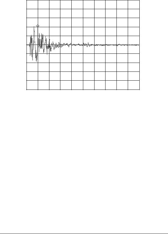
Input |
CH1 Rng: 1.0012 Vpk |
CH2 |
Rng: 631.706 mVpk |
|
CH3 Rng: 2.5149 Vpk |
CH4 |
Rng: 2.5149 Vpk |
Date: 10-02-96 Time: 08:47:00 PM |
|
|
A: CH1 Time |
X:38.0859 ms |
Y:1.06837 V |
2.5 |
|
|
V |
|
|
Real |
|
|
500 |
|
|
mV |
|
|
/div |
|
|
-2.5 |
|
|
V |
-9.7656ms |
489.7461ms |
|
||
Quantifying Time Trace Results
Use the marker knob to read the amplitude at any time during the trace. Rotate the knob on the AGILENT 35670A front panel until the marker indicator (the small diamond following the spectral trace) is placed at the desired time. The time and amplitude at this bin is presented as X and Y values at the top of the trace. Units of [s] and [Vrms] or [grms] identify the results.
Peak tracking is very useful for determining maximum amplitude of positive peaks in the time domain:
•Press the [Marker] hardkey.
•Press [PEAK TRK ON OFF] softkey (F6) until ON is highlighted.
Care must be taken with negative peaks, however, because PEAK TRK ON only looks for the maximum value, and large negative peaks will be ignored.
14

AGILENT 35670A
Supplemental Operator’s Guide
Section 7 : Measuring Dual Channel Spectra
This section contains procedures for setting up and measuring a dual channel spectrum using an AGILENT 35670A Dynamic Signal Analyzer. Procedures are similar to those in the section “Measuring Single Channel Spectrum,” however display setup and results are different and will be described here.
To set up the analyzer for a dual channel spectrum measurement, proceed as follows:
Presetting the Analyzer
•Press the green [Preset] hardkey
•Press [DO PRESET] softkey (F1).
•Press the [Pause/Cont] hardkey if desired.
Selecting Dual Channel Operation
Measure two signals with the default two-channel instrument mode. If the analyzer has been changed to 1 or 4 channel operation, then follow these steps:
•Press the [Inst Mode] hardkey
•Press [CHANNELS 1 2 4 ] softkey (F7) until 2 is highlighted.
Selecting Frequency Span
Reduce the span to 800 Hz as follows:
•Press the [Freq] hardkey
•Enter 800 and then press the [Hz] softkey (F2)
Displaying Dual-Channel Power Spectrum Measurements
To see the results of a dual-channel measurement, the analyzer’s display format must be changed to display two traces. Proceed as follows:
•Press the [Disp Format] hardkey.
•Press the [UPPER/LOWER] softkey (F3)
•Press the [Active Trace] hardkey.
•Press the [A] softkey (F1).
•Press the [Meas Data] hardkey.
• |
Press the |
[CHANNEL 1 2 3 4] softkey (F1) until 1 is highlighted. |
• |
Press the |
[PWR SPEC CHANNEL 1] softkey (F3) |
•Press the [Scale] hardkey.
• Toggle the [AUTOSCALE ON OFF] softkey (F1) until ON is highlighted.
•Press the [Active Trace] hardkey again.
•Press the [B] softkey (F2).
15
AGILENT 35670A
Supplemental Operator’s Guide
•Press the [Meas Data] hardkey.
• Press the [CHANNEL 1 2 3 4] softkey (F1) until 2 is highlighted.
•Press the [Scale] hardkey.
•Toggle the [AUTOSCALE ON OFF] softkey (F1) until ON is highlighted.
Note: many of these keystrokes are not necessary if performed in the given order because the analyzer defaults to many of these settings.
To acquire dual channel spectra,
•Press the yellow [Start] hardkey.
Meas Data |
A: CH1 Pwr Spec |
B: CH2 Pwr Spec |
[FFT] |
C: CH1 Time |
D: CH2 Time |
Date: 10-02-96 Time: 08:49:00 PM |
|
||
A: CH1 Pwr Spec |
X:60 |
Hz |
Y:147.382 mVrms |
1 |
|
|
|
Vrms |
|
|
|
LogMag |
|
|
|
6 |
|
|
|
decades |
|
|
|
1 |
|
|
|
uVrms |
|
|
|
0Hz |
|
|
800Hz |
B: CH2 Pwr Spec |
X:60 |
Hz |
Y:80.4887 mVrms |
1 |
|
|
|
Vrms |
|
|
|
LogMag |
|
|
|
4 |
|
|
|
decades |
|
|
|
100 |
|
|
|
uVrms |
|
|
|
0Hz |
|
|
800Hz |
Using Markers with Dual Channel Measurements
Each trace has independent marker control. All functions available for a single marker are possible with both markers. To set up individual, independent markers on each channel, follow these steps:
•Press the [Active Trace] hardkey.
•Press the [A] softkey (F1).
•Press the [Marker] hardkey.
•Toggle the [MARKER ON OFF] softkey (F1) until ON is highlighted.
16
AGILENT 35670A
Supplemental Operator’s Guide
Use the marker knob to read the amplitude at any measured frequency for Channel 1 in Trace A.
To set up the marker for Channel 2 in Trace B,
•Press the [Active Trace] hardkey.
•Press the [B] softkey (F2).
•Press the [Marker] hardkey.
•Toggle the [MARKER ON OFF] softkey (F1) until ON is highlighted.
The marker knob is now active for Trace B, which is Channel 2. To gain control of the marker on Trace A again, make it the active trace as follows:
•Press the [Active Trace] hardkey.
•Press the [A] softkey (F1).
Coupled Markers
Markers on multiple traces can be coupled so that one marker will always track the frequency specified in another trace. This makes comparisons of level differences across channels simple. To set up coupled markers so that Trace B will follow the marker frequency specified in Trace A, do the following:
•Press the [Active Trace] hardkey.
•Press the [A] softkey (F1).
•Press the [Marker] hardkey.
•Toggle the [COUPLED ON OFF] softkey (F1) until ON is highlighted.
Move the knob to move the marker in Trace A. Notice that the marker in Trace B moves to the same frequency.
Coupled Markers with Peak Tracking
Coupled markers can be further used to track a peak frequency in Trace A and determine the response amplitude at the peak frequency in Trace B. To do this, leave coupled markers on, as above, then set up peak tracking in Trace A as follows:
•Press the [Active Trace] hardkey.
•Press the [A] softkey (F1).
•Press the [Marker] hardkey.
• Toggle the [PEAK TRK ON OFF] softkey (F1) until ON is highlighted.
•Press the yellow [Start] hardkey.
Notice that the marker in Trace A moves to the peak value, whereas the marker in Trace B moves to the same frequency as determined in Trace A.
17

AGILENT 35670A
Supplemental Operator’s Guide
Section 8 : Improving Dual Channel Measurement Results
Maximizing Dynamic Range
Autoranging to maximize the dynamic range of measurements in the AGILENT 35670A can function on all channels simultaneously. Therefore all capability previously mentioned for single-channel front-end ranging is available for dualchannel operation.
To set up autorange on all channels, follow these steps:
•Press the [Input] hardkey.
•Press [ALL CHANNELS] softkey (F2).
•Select the [CH* AUTO RANGE] softkey (F6)
For signals that are not steady, use CH* AUTO UP ONLY. CH1 AUTO UP ONLY can be used for all channels to set up modal impact testing. To set up this condition:
•Press the [Input] hardkey.
•Select the [CH* AUTO UP ONLY] softkey (F5).
To set up the same fixed range on all channels:
•Press the [Input] hardkey.
• Select the [CHANNEL * RANGE] softkey (F3)
•Enter the range, either in units of g or Volts.
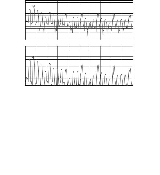
Dual Channel Averaging
Averaging to reduce measurement variance applies to all channels being measured. Dual channel averaging is set up the same as single channel averaging:
•Press the [Avg] hardkey.
•Press the [NUMBER AVERAGES] softkey (F2), enter 10, then press the
[ENTER] softkey (F1).
•Press the [AVERAGE TYPE] softkey (F3)
•Press the [RMS] softkey (F1)
•Press the [Avg] hardkey.
•Turn on averaging by pressing the [AVERAGE ON OFF] softkey (F1) until ON is highlighted.
18

AGILENT 35670A
Supplemental Operator’s Guide
Avg |
Type: RMS |
Number: 10 |
[FFT] |
Update Rt: 5 |
Overlap: 0 % |
Date: 10-02-96 Time: 08:51:00 PM |
|
|
|
||
A: CH1 Pwr Spec |
X:60 |
Hz |
|
|
Y:112.185 mVrms |
1 |
|
|
|
|
|
Vrms |
|
|
|
|
|
LogMag |
|
|
|
|
|
5 |
|
|
|
|
|
decades |
|
|
|
|
|
10 |
|
|
|
|
|
uVrms |
|
|
|
|
|
0Hz |
|
|
AVG: |
10 |
800Hz |
B: CH2 Pwr Spec |
X:60 |
Hz |
|
|
Y:95.0385 mVrms |
100 |
|
|
|
|
|
mVrms |
|
|
|
|
|
LogMag |
|
|
|
|
|
4 |
|
|
|
|
|
decades |
|
|
|
|
|
10 |
|
|
|
|
|
uVrms |
|
|
|
|
|
0Hz |
|
|
AVG: |
10 |
800Hz |
19

AGILENT 35670A
Supplemental Operator’s Guide
Section 9 : Measuring Dual Channel Time Waveforms
This section contains procedures for setting up and measuring a single channel time waveform using an AGILENT 35670A Dynamic Signal Analyzer. Included are steps to select single channel operation, set up the trace time length, and set up triggering to capture a transient event. Instructions will also be presented to scale the time trace.
Selecting Dual Channel Operation
To measure a single-channel spectrum, turn on the AGILENT 35670A. The default instrument mode is dual-channel operation.
Note: if the AGILENT 35670A was already turned on and in an unknown state, then preset the analyzer by doing the following:
•Press the green [Preset] hardkey.
•Press [DO PRESET] softkey (F1).
This always returns the analyzer to dual-channel operation.
Selecting Time Record Length
Time record length can be entered directly or indirectly. It is entered directly under the [Freq] hardkey as follows (this example sets up a 0.25 second time record):
•Press the [Freq] hardkey
•Press the [RECORD LENGTH] softkey (F8)
•Enter 0.25 and then press the [S] softkey (F1)
Time record length can also be specified indirectly by entering frequency and resolution in lines. The relationship between time record length (T), lines of resolution (N), and frequency (F) is:
T = N (1024.F)
For 400 lines of resolution (default) and 1600 Hz span, the time record length should be 400/(1.024*1600) ≈ 0.25 seconds. The table showing the relationship between lines, span, and time record length can be found in the section on Single Channel Time Waveforms.
Displaying Dual Time Waveforms
Dual time waveforms can be shown in the UPPER/LOWER display format, with AUTO SCALE turned ON, as follows:
•Press the [Disp Format] hardkey.
•Press the [UPPER/LOWER] softkey (F3).
•Press the [Active Trace] hardkey.
•Press the [A] softkey (F1)
•Press the [Meas Data] hardkey.
20

AGILENT 35670A
Supplemental Operator’s Guide
• |
Press the |
[CHANNEL 1 2 3 4] softkey (F1) until 1 is highlighted. |
• |
Press the |
[TIME CHANNEL 1] softkey (F5) |
•Press the [Scale] hardkey.
• Toggle the [AUTOSCALE ON OFF] softkey (F1) until ON is highlighted..
•Press the [Active Trace] hardkey.
•Press the [B] softkey (F1)
•Press the [Meas Data] hardkey.
• Press the [CHANNEL 1 2 3 4] softkey (F1) until 2 is highlighted.
•Press the [TIME CHANNEL 2] softkey (F5)
•Press the [Scale] hardkey.
•Toggle the [AUTOSCALE ON OFF] softkey (F1) until ON is highlighted.
Arming Dual Channel Time Measurements
To manually arm a dual channel time measurement, proceed the same as for the single channel case:
•Press the [Trigger] hardkey.
• Select the [ARM SETUP] softkey (F7)
•Select the [MANUAL ARM] softkey (F2)
•Press the yellow [Start] hardkey to begin the measurement.
•Press the [Trigger] hardkey.
Then to arm a single time record,
•Press the [ARM] softkey (F9)
One time record will be captured and displayed. To capture another time record,
•Press the [ARM] softkey (F9) again.
Triggering a Dual-Channel Time Measurement
Either channel may be monitored to initiate a trigger for a measurement. Setting up the trigger event is the same as for single channel time waveforms, except that channel 1 or channel 2 must be selected as the trigger. To specify the trigger channel, proceed as follows:
•Press the [Trigger] hardkey.
•Press the [CHANNEL 1 2 3 4] softkey (F3) until 1 is highlighted.
This sets up the analyzer to trigger off an event on channel 1. To set up channel 2 as the trigger channel, do the following:
•Press the [Trigger] hardkey.
•Press the [CHANNEL 1 2 3 4] softkey (F3) until 2 is highlighted.
21
 Loading...