


Instructions
for the use and installation of gas cookers
Notice d’emploi
pour l’installation et l’utilisation des cuisinieres à gaz
GB
F
ATTENTION
This owner’s manual is valid for the Country mentioned on the appliance.
Keep this manual close to hand and preserve it for any further consultation.
The packing components (plastic bags, foamed polystyrene, nails, etc...) are a source of potential risk; never leave them within the reach of children.
If you use the grill keep the oven door half-open and the grill deflector assembled as shown in the instructions booklet. The glass cover (only on some models), before lighting the over burners of the top and until their turning off, shall be in open position; it is important to avoid any contact with cookware during the cooking in order to save from a dangerous overheating.
Important
After the cooker use it is recommended to:
1)always check that the knobs are in the “ ” position.
2)close the cock of the gas cylinder (if you use liquefied gas) or the supply cock (in case of natural gas).
3)periodically check the wear of the hosepipe and replace it if necessary. Do not repair it.
IMPORTANT:
The appliance must be installed only by qualified and competent technicians in compliance with the national provisions in force. Any modification that should be necessary to the domestic system in order to install the appliance shall be carried out by qualified technicians only. The manufacturer declines all responsibility for any damage caused by the non-observance of the rules in force or due to an improper installation.
For any intervention please apply to an authorised aftersales servicing centre and ask for original spare parts.
REMARK: during and after the use, the glass of the oven door and accessible parts can be very hot; it is therefore necessary to keep children away from the appliance.
-Make sure that there is a regular air circulation around the gas appliance. A poor ventilation reduces the oxygen.
In case of doubts consult the installer.
-The forming of fat or other food can start a fire. Carefully mind the cooking with oils and fats.
-This appliance has been designed exclusively for the cooking of food. Any other use (e.g. environment hating) is considered improper and dangerous.
-Do not install the cooker near flammable material (e.g. curtains, tea towels, etc...)
-Never clog the holes on the bottom of the oven. Do not cover with aluminium sheets the oven walls, especially the lower side.
-Always close the cock of gas supply before any cleaning and maintenance operations.
-The oven parts in contact with food are made with materials in compliance with the provisions of Directive EEC 89/109 dated 21/12/88.
-The cooker complies with the European Directives as to gas EEC 90/395, EEC 93/88 and provisions EN 30-11 and EN 2-1.
-Before operating on the unit remove the plastic films.
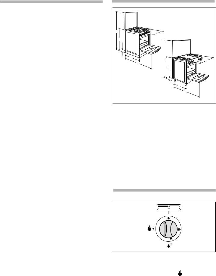
MODELS SPECIFICATIONS
|
|
Fig. 1 |
2 |
|
|
a |
B |
|
|
|
|
1 |
|
|
a |
|
|
100 |
|
|
C1 |
2 |
|
|
a |
B |
|
C2 |
|
|
|
|
|
|
1 |
|
|
a |
|
|
100 |
|
|
C1 |
|
|
C2 |
COOKER DIMENSIONS |
|
90x60 |
|
90x60 |
AND CHARACTERISTICS |
|
with cylinder |
|
|
|
|
compartment |
|
|
|
|
|
|
|
Height of top |
a1 |
85 ± 2 cm |
|
85 ± 2 cm |
|
|
|
|
|
Depth |
c1 |
60 cm |
|
60 cm |
|
|
|
|
|
Width |
B |
90 cm |
|
90 cm |
|
|
|
|
|
Height of topof open lid |
a2 |
141 ± 2 cm |
|
141 ± 2 cm |
|
|
|
|
|
Depth with oven door open c2 |
98 cm |
|
104 cm |
|
|
|
|
|
|
Working capacity |
|
58 dm3 |
|
135 dm3 |
|
|
|
|
|
Class |
|
2 subclass 1 |
|
2 subclass 1 |
|
|
|
|
|
Burners |
|
Burners adaptable for operation with LPG - natural gas |
||
|
|
|
|
|
Operating voltage |
|
230 Volt - 50 Hz |
|
|
|
|
|
|
|
INSTRUCTION FOR USE
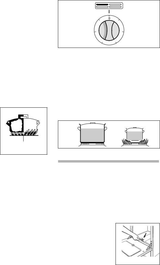
COOK-TOP
|
gas supply closed |
|
maximum |
|
gas position |
|
|
|
minimum |
Fig. 2 |
gas position |
BURNERS USE
MANUAL LIGHTING OF THE COOK-TOP BURNERS
Put a lighted match to the burner, hold down and press the proper knob to the left up to the max  .
.
Turn the knob to the minimum position in order to reduce the flame  (small flame).
On the control panel next to each knob is drawn a flame schema where it is indicated the burner position to which the knob refers to. (fig. 2).
GB |
|
3 |
|
LIGHTING THE BURNERS OF THE COOK-TOP EQUIPPED WITH SAFETY THERMOCOUPLE
(automatic stop of gas supply in case of accidental flame putting out).
In case of lack of electricity light the burner with a match, following the instructions given in the previous paragraph. After lighting keep hold down the knob for about 10 seconds. The gas supply can be cut off by turning the knob clockwise on the position  (gas supply closed).
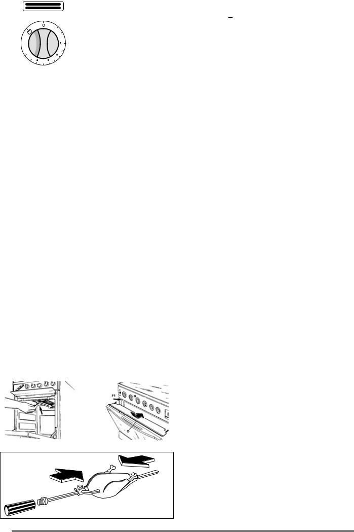
Suggestions for saving energy
Avoid using pans that are too small for the burner, so that the flames don’t reach high up the sides of the pan. When the contents has boiled, reduce the flame setting to a simmer by turning the knob anticlockwise. To facilitate saving gas, the hob has burners with different diameters and power ratings. Use the appropriate burner for each type of pan, as detailed below:
The Oven and Grill Configuration
Rapid burner |
R |
Pan diameter from 24/25 cm |
Semi-rapid burner |
B |
Pan diameter from 16/18 cm |
Auxiliary burner |
A |
Pan diameter from 12/14 cm |
|
|
|
Kwali triple flame burner BK |
Pan diameter from 24/25 cm |
|
|
|
|
REMARKS
The gas cooker during its
operating produces heat and humidity in the room where it
is installed.
Therefore the local needs a good airing; keep unclogged the opening of the natural ventilation and activate the airing mechanical device (extractor hood or electric fan).
In case of an intensive or long use of the appliance it is necessary additional airing, e.g. open a window or more effective ventilation increasing the power of the mechanical aspiration (if any).
If the appliance is equipped with cover in tempered glass, this can burst if overheated.
Turn off any burner before closing the cover.
The cooker with enamelled support grids are supplied with a small reduction grid which shall be used for heating cookware of small diameter, exclusively on the auxiliary burner.
In case of convex pots (wook-type) it is necessary to use on the Kwali triple-crown burner grid, the special reduction grid, while if you use normal cookware with flat bottom it is necessary to put on the grid a ring in order improve the burner functioning.
USING ELECTRIC PLATES
The electric heating plates can be put on by turning the proper knob on the control panel (fig. 4). A yellow light indicates its functioning. The cooker is equipped with the following plates:
Standard plate: Ø 110 P = 800 700 W
Ø145 P = 1000 W Rapid P = 1500W
Ø180 P = 1500 W Rapid P = 2000W
Every plate is controlled by a 7 positions selector (6 working position + 0). The highest position corresponds to the max power, while the position 1 is the minimum.
The right quantity of heat for cooking can be obtained by selecting intermediate positions.
|
6 |
|
1 |
|
|
|
|
5 |
|
|
2 |
|
|
4 |
3 |
|
|
|
Fig. 4
PRACTICAL ADVICE
During the first plate insertion and in order to eliminate any trace of residual humidity in the insulator, arrange for its drying by switching on the plate for 30 minutes in position 1 without cookware.
It is possible to save energy consumption by using cookware with flat and thick bottom (fig. 5). Never use cookware with diameter lower than the plate.
Do not forget the plates on without cookware or with empty vessels and make sure that the bottom of the cookware is perfectly dry.
For a good preservation, after the use the plate shall be lightly greased with a cloth soaked with oil so that the surface appears clean and shining.
YES |
NO |
Fig. 5
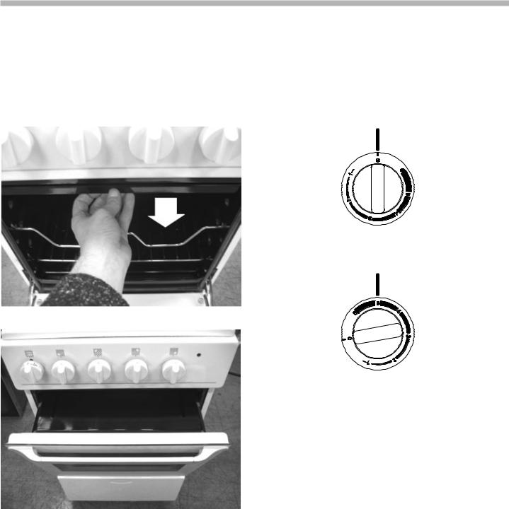
OVEN AND GRILL
USING THE GAS OVEN Manual lighting of the oven
Open the oven door. Put a flame to the proper holes present on the bottom of the oven (fig. 6), hold down and turn to the left the proper knob on the control panel marked by the  symbol up to the maximum position (big flame).
Once it is on, keep pressed the knob for about 10 seconds and make sure that the burner is lighted observing it by the hole (fig. 6). The flame can be reduced turning the knob up to the minimum position (small flame) and acting on the temperature selected.
Before introducing food it is recommended to heat the oven for 15 minutes at the maximum position. For the lighting of the oven burner equipped with thermostat, follow the above mentioned instructions, keeping in mind that the indicator of the
control knob shall be turned to
Fig. 6
the max. position (fig. 7).
4 |
|
GB |
|
||
|
|
|
|
|
The oven burners are provided |
|
|
|
|
|
with safety thermocouple |
|
|
|
|
|
(automatic stop of gas supply |
|
|
|
|
|
||
|
|
|
|
||
|
|
|
min |
in case of accidental flame |
|
|
|
|
putting out). |
||
|
|
|
150 |
||
|
|
|
Therefore keep pressed the |
||
|
|
|
|
||
|
|
|
175 |
knob for about 10 seconds. |
|
max |
|
|
If the burner is off, release |
||
285 |
|
|
205 |
||
235 |
the knob and wait for a |
||||
|
|
||||
Fig. 7 |
|
|
|
minute before trying again |
|
|
|
|
with the lighting. |
||
|
|
|
|
||
|
|
|
|
||
In case of accidental burner put out, turn the knob in closed
position and wait for one minute before relighting it. REMARK
During and after the use, the glass of the oven door and accessible parts can be very hot, it is therefore necessary to keep children away from the appliance. The oven parts in contact with food are made with materials in compliance with the provisions of Directive EEC 89/109 dated 21/12/88.
INDICATIVE TABLE FOR USING THE OVEN
The data reported are purely as and indication: experience and personal taste will suggest you any variations for the best use of the appliance.
POSITION |
OVEN |
FOOD |
COOKING |
|
OF THE |
TEMPERATURE |
TIME |
||
|
||||
OVEN GRID |
°C |
|
|
|
HIGH |
150 - 170°C |
Meringue - Sweets |
40 min. |
|
Legumes - Flat bread |
45 min. |
|||
|
|
|||
MEDIUM |
180 - 200°C |
Soufflè - Puddings |
35 min. |
|
HIGH |
Pigeon - Pheasant |
65 min. |
||
|
||||
MEDIUM |
210 - 230°C |
Cakes - Short pastry |
30 min. |
|
HIGH |
Chicken - Veal |
80 min. |
||
|
||||
MEDIUM |
240 - 260°C |
Lamb - Pork |
60 min. |
|
Dentex - Lasagne |
90 min. |
|||
|
|
|||
MEDIUM |
270 - 280°C |
Pizza - Gratins |
30 min. |
|
LOW |
Bread - Fish |
50 min. |
||
|
USING THE GAS GRILL
Manual lighting of the grill burner
Open the oven door completely. Put a lighted match to the grill burner which is on the upper side of the oven (fig. 8). Press and turn to the right the oven knob up to the grill position (fig. 7). Check that the flames of the burner are regularly lighted on both sides.
Fig. 8 |
|
Fig. 9 |
|
|
|
Fig. 9/1 |
GB |
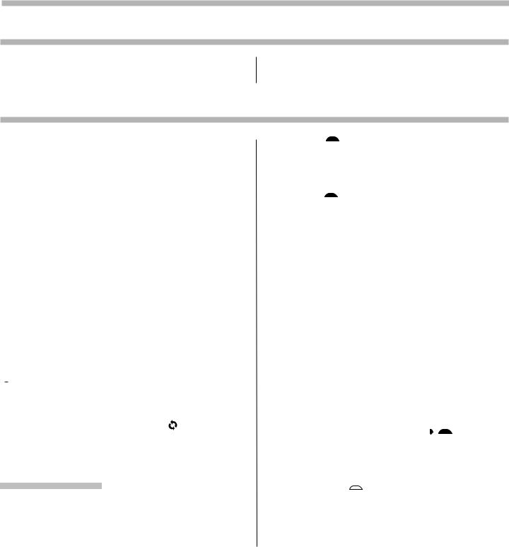
Using the turnspit
(available on some models)
The turnspit is operated by turning the oven knob to encounter the symbol  together with the grill.
First of all, place the food on the spit, using the two special forks to hold it in place. Take care to distribute the weight evenly, to prevent unnecessary strain on the motor (fig. 9/1). Then place the end of the spit in the motor hole, and the opposite end on its special support. Unscrew and remove the plastic handle and turn on the grill. The oven burners are provided with safety thermocouple (automatic stop of gas supply in case of accidental flame putting out). Therefore keep pressed the knob for about 10 seconds.
If the burner is off, release the knob and wait for a minute before trying again with the lighting.
In case of accidental burner put out, turn the knob in closed position and wait for one minute before relighting it.
ATTENTION
During the use of the grill the door of the oven shall be opened. It is besides necessary to insert the grill deflector - D- as shown in fig. 9. Put the tongues in the slots F or P placed on the upper front side of the oven. Then fix the deflector pressing it downwards.
This prevents an overheating of the control panel available.
IN SOME MODELS IT'S POSSIBLE TO GRILL WITH THE OVEN DOOR CLOSED ,IN THIS CASE READ THE ALLEGATE INSTRUCTION "COOL DOOR SYSTEM"
ATTENTION
During the grill functioning, the accessible parts can be hot. Keep the children at a safe distance.
COOKING WITH THE GRILL
Before introducing the dishes, let the radiant plate grow redhot, and then arrange the dishes on the grid and position the dripping-pan on the immediately lower guides for the dripping collection. The oven parts in contact with food are made with materials in compliance with the provisions of Directive EEC 89/109 dated 21/12/88.
COOL DOOR SYSTEM
During use of the grill burner on its own or simultaneously with theoven burner, the oven door must be SHUT.
This prevents overtheating of the control panel.
CAUTION: Check that the gas pressure at the cooker inlet isas required:
LPG: |
280-300 mm H2O |
Natural Gas: |
180-200 mm H2O |
Pressure different from those indicated may cause the applianceto overheat dangerously.
5
USING THE ELECTRIC OVEN
WARNING LIGHTS
Thermostat function orange pilot light lamp it indicates the phase of oven heating.
The red pilot light signals that a heating element is operated.
HOW TO COOK
At the first use of the oven, it’s normal to smeel the protective oils used in manufacture burning off.
Leave oven on maximum setting for approximately one hour before use.
N.B. Before carryng out cleaning, disconnect the appliance from electrical supply.
At the end of the initial heating, let the oven cool down and clean he inside with detergent and warm water. Before using, wash all grid accessories, baking-pan and trays.
General information and use precautions
-Always hold the handle in the middle, to open the oven door.
-When you open the oven door, beware hot vapour.
-Use protective gloves to insert or to extract containers from the oven.
-Use containers resistant to the temperatures indicated on the thermostat knob.
-After use of the oven, be sure that all controls are in the off position.
Oven light
The symbols present on the oven control knob are different according to the models. The first function common to all is the oven light bulb switching on, identified by the symbol
 . Once selected, the bulb light is on during other oven functions.
Turnspit |
|
The turnspit, marked with the symbol |
is an optional |
available only in some models. Its symbol is next to the oven function symbols, for example 
 when selecting the function “simple grill” the “turnspit” will automatically operate too.
Cooking functions
Simple grill 
This function operates the top central element which radiates heat directly over the foods. Set the max temperature by means of the thermostat. The oven door must be kept closed.
Double grill 
This function switches on both top elements to radiate heat directly over the foods it is possible to use this function turning the thermostat knob to the max temperature 200°c The oven door must be kept closed.
Static oven 
Traditional cooking with natural convention. This function operates the top and bottom elements and the foods are evenly cooked. Turn the thermostat knob to the chosen temperature.
This function is suitable for cooking most food (meat, fish, bread, pizza and so on).
Fan oven 
This function operates the back circular element and the heat is very quickly spread in the oven by means of an electric/motor fan. The foods are rapidly and evenly cooked even if placed on more than one shelf.
It is possible to use this cooking mode turning the thermostat knob to the chosen temperature.
Fan double Grill 

This function operates both top elements to radiate the heat directly over the food; the heat is spread very quickly in the oven by means of an electric fan.
It is possible to use this function, turning the thermostat knob to the temperature 200 °C.
This cooking mode is particularly suitable to get an evenly and crisp browning.
Conventional electric fan cooking 

This function operates top and bottom elements and the heat is spread over the foods by means of an electric fan. Turn the thermostat knob to the chosen temperature. This cooking mode is suitable for cooking foods on a single shelf.
Delicate cooking 
This function operates the bottom element. Turn the thermostat knob to the chosen temperature.
This mode is suitable for re-cooking, if it is necessary to increase the cooking degree in the lower side of foods.
6 |
|
GB |
|
||
|
USING THE ELECTRIC GRILL
Caution:
Model 90x60 with cylinder compartment Gas oven and electric grill
When using the grill, open the oven door and fit the guard as shown in the diagram.
The guard becomes very hot during use; keep children well away. After cooking, allow the guard to cool.
Warning: Model 90x60
Gas oven and electric Grill
when using the electric grill turn the oven dial to 0, keep the oven door closed, turn the energy setting (fig A) to the highest position 5 for 90x60 models (fig B) .
Fig. A
Fig. B
GB |
|
7 |
|
||
|

ATTENTION
-During the functioning the oven door is hot. It is recommended to keep children at safe distance.
The use of detergents, abrasive powders or paste, can damage the surfaces.
It is recommended to clean immediately any lemon spots, vinegar and acid substances, in order to preserve the enamel brightness.
The grids and burners can be taken away and easily washed in warm water and soda.
OVEN
It is advisable to clean the oven periodically. While it is still warm clean with a cloth soaked with warm water and detergent, followed by a careful rinsing and drying.
The bottom of the oven can be easily extracted and washed in the washbasin together with dripping-pan and gridiron shelf.
IMPORTANT:
Check the wear of the gas hosepipe connecting the cooker to the cylinder and replace it in case of anomalies. It is recommended to change it yearly; in any case within the date impressed on the hose.
The replacement of spare parts and maintenance operations shall be carried out by qualified personnel only.
GENERAL GUIDELINES
All servicing operations described in this section must be carried out by qualified personnel only.
Before starting any servicing operations on a cooker, it must be unplugged or switched off at the mains supply. If work is to be carried out on the electrical or gas components underneath the hob (e.g. switches, thermostat taps, etc.) follow the order shown in Fig. 11 below.
Fig. 11
1)remove the pan supports.
2)remove the burners and unscrew the screws as shown in Fig. 11.
3)unscrew the 4 screws on the back of the cooker (Fig. 12). Having completed the above, remove the hob.
Fig. 12
To remove the control panel, follow the instructions in Fig. 13, removing knobs “A” and unscrewing the screws “B”. To replace the hob and control panel, repeat the operation in reverse.
Fig. 13
REPLACEMENT OF THE TAPS
When replacing a tap, follow the instructions below:
-Remove the knobs by pulling.
-Remove the hob and the control panel following the sequence of instructions in Fig. 11-12-13.
-Unscrew the lock nuts “C” from the junction ramp between the burner (Fig. 14).
-Lift the mounting support and unscrew screws “E” (Fig.15).
-Partially lift the ramp.
-Unscrew screws “F” to remove the tap.
-Replace the seal when replacing a tap to ensure a perfect seal between the body and the ramp.
Fig. 15
Fig. 14
REPLACEMENT OF THE BURNERS AND SWITCHES
-To replace these accessories, remove the hob following the sequence of instructions in Fig. 11-12-13.
-To take the burners apart follow the sequence of instructions in Fig. 15b.
Unscrew the lock nuts “C” and “D” and screws “E” (Fig.15b)
Fig. 15b
8 |
|
GB |
|
||
|

USE OF ACCESSORIES
Timer
Your range can be fitted with this accessory that you can wind by rotating the corresponding knob clockwise by one complete turn and set the pointer to the desired cooking time (expressed in minutes) by rotating the knob counterclockwise.
The set time running out will be signaled by a bell.
Electric timer
Your range can be fitted with this accessory acting both as a clock and as a timer as well. To set hour push and rotate the small knob counterclockwise. To set minutes rotate the small knob counter clockwise without pushing it.
Timer with cooking end function
Your range can be fitted with this double functional accessory: it can show the cooking time that has already passed and automatically turn off the oven. You can set the desired cooking time by rotating the timer knob clockwise by one complete turn and set the pointer to the desired cooking time (expressed in minute); when this time has passed the acoustic warning signal switches on and contemporaneously the automatic cooking end device starts.
As far as the oven connection modes are concerned please refer to the handbook specific paragraphs.
If you desire to use the oven without the timer function you should turn the knob to the symbol 
 (manuel).
N.B. When the knob pointer is set to “0” position, oven cannot work.
Electric clock supplied with cooking end device
Range can be fitted with this double functional accessory: it consists of a clock able to turn off oven automatically when the set cooking time has run out.
To set hour push and rotate the small knob counterclockwise. To set minutes rotate the small knob counterclockwise without pushing it. When the set time has run out the acoustic warning signal starts to inform that oven is off.
Turn the knob to the symbol  to stop it.
If you desire to use oven without setting a cooking time you should rotate the knob pointer counterclockwise to the symbol 
 (manuel).
N.B. When the knob pointer is set to “0” position and to symbol, oven cannot work.
Electronic programmer
Your range can be fitted with this accessory whose main functions are:
-Clock (to be set with push buttons 2 and 3).
-Timer (to be set with push button 1).
-Cooking time (to be set with push button 2).
-Cooking end time (to be set with push button 3).
-Manual working (to be set with push button 4).
-Regulation of times “backward” (to be set with push button 5).
-Regulation of times “forward” (to be set with push button 6).
The digital display “D” (see pict. 4 at the end of this handbook) shows the hour, the cooking time and the cooking end time.
Time setting
After the electric connection or a lack of current, on the display the “AUTO” e “0.00” signals will flash at the same time. Push and release contemporaneously push buttons 2 and 3 and start setting the current hour by pushing either button 4 or 5 within 4 seconds. Once the setting is over no symbol will be on.
Timer
Push button 1 and select your cooking time by means of either button 4 or 5.
The symbol will lit up.
When the set time has run out, the acoustic warning signal starts and the symbol will flash. After the bell disconnection that symbol will disappear.
Half-automatic working mode (cooking time)
By pushing button 2 and setting the cooking time by means of button 5, both the “AUTO” and the symbol will lit up. When the set time has run out, the symbol will switch off while the “AUTO” symbol flashes and the acoustic warning signal starts.
Half-automatic working mode (end of cooking time)
By pushing button 3 and setting the end of cooking time by means of button 5, both the “AUTO” and the symbols will lit up. When the set time has run out, the symbol will switch off while the “AUTO” symbol flashes and the acoustic warning signal starts.
Automatic working mode (postponed cooking start time)
First you should set your cooking time (both the “AUTO” and the  symbols will lit up) and then the cooking end time, the


 symbol will switch off as previously stated.
The 


 symbol will lit up again when the oven starts baking. When cooking time has run out, the


 symbol will switch off while the ”AUTO” symbols flashes and the acoustic warning signal starts.
Manual working
Manual working is possible only after having cleared the automatic program by pushing button 3. The “AUTO” symbol disappears and no other symbols lit up.
Acoustic warning signal
The acoustic warning signal starts at the end of a program and lasts about two minutes. To interrupt it you should push one of the function buttons.
Program start and check
Program starts after about 4 seconds from the setting. It is possible to check the set program at any time by pushing the corresponding button.
Correction and cancellation of program
It is possible to correct the set program at any time by first pushing the relative programming button and then buttons 4 or 5. It is possible to cancel a program by changing the set time to “0.00”. By cancelling the working time you will automatically cancel the working end time and vice versa. Oven automatically switches off while the “AUTO” symbol flashes. Push button 3 to set the programmer to manual working mode.Time cannot be corrected when the automatic working program is on.
FEED CABLES TYPES |
TYPE OF |
INPUT |
AND SECTION |
CABLE |
220 V~ |
TOTAL GAS |
H05 RR-F |
3x0,75 mm2 |
MIXED UP TO 660 W |
H05 RR-F |
3x1 mm2 |
MIXED UP TO 1320 W |
H05 RR-F |
3x1,5 mm2 |
MIXED UP TO 2200 W |
H05 RR-F |
3x2,5 mm2 |
MIXED UP TO 3520 W |
H05 RR-F |
3x4 mm2 |
GB |
|
9 |
|
||
|
TECHNICAL INFORMATION FOR THE INSTALLATION
The installation and regulations shall be carried out by qualified technicians only. After removing external packaging and inside packing of movable parts, make sure of the integrity of the appliance. In case of doubts do not use the appliance and turn to qualified technicians.
Never leave packing components (carton, bags, foamed polystyrene, nails.....) within the reach of children as they represent potential dangers.
ASSEMBLY OF ADJUSTABLE LEVELLING FEET
Remove the packaging of the cooker. Assemble the feet which are in the accessories kit, fitting them in the proper fixed seats placed on the four corners of the cooker.
(fig. 16 – fig. 16/a). Align or level the cooker with other furniture by adjusting the foot.
Fig. 16 |
|
Fig. 16/A |
|
|
|
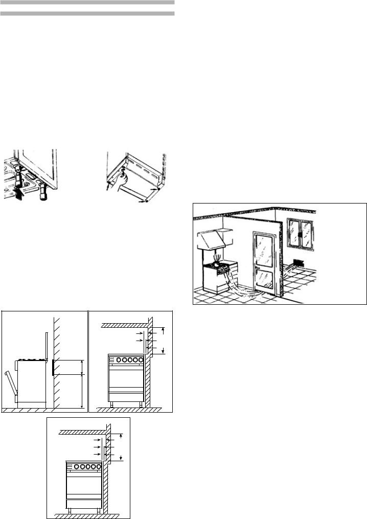
REMARKS FOR THE INSTALLATION
The installation shall be carried out in compliance with the national rules in force. Install the appliance in a well-aired room. Check that the flux of the gas meter and the diameter of the ducts have enough capacity for all the appliances and that the connectors are water-tightness. The gas cookers belong to Class I and therefore they shall not be put closer to furniture. The walls next to the cooker shall be resistant to a temperature of 75° C. (fig. 17) or covered with insulating material. The cooker shall be installed at a distance of 20 mm from the walls and the cook-top 650 mm from the suspended wall unit (fig. 17/a). The gas cookers belong to class II can be lean agains the walls ( fig.17/b )
Fig. 17 |
25 cm |
60 cm |
Fig. 17/A |
|
|
|
150 |
Min |
Min |
|
20 |
Min |
||
650 |
|||
|
|
Fig. 17/b
150 mm Min |
Min |
|
|
0 mm Min |
650 mm |
CLASS II under Class I |
TypeY
Dimensions shown apply to BOTH sides of the appliance
Applies to base &wall units (if fitted)
ROOMS VENTILATION
Attention: this appliance can be installed and used only in constantly ventilated rooms according to the national rules in force. The right functioning of the cooker is ensured by the installation in a constantly ventilated room. The flow of air for a regular gas combustion and ventilation shall not be less than 20 m3. The natural influx of air shall be directly from the outside through openings on the wall of the room with a cross section of at least 100 cm2. These openings shall be made in a way that can’t be clogged. It is allowed the indirect airing through the extraction of air from adjacent rooms (fig. 18) in compliance with the national regulations in force.
ATTENTION:
The section of the ventilation opening of a cooker with burners not fitted with safety thermocouple should be at least 200 cm2.
POSITIONING
The gas cookers shall discharge smokes and gases from combustion by means of hoods connected to chimneypots, flues or directly outside. In absence of a hood it is permitted the use of a ventilator installed on a window or on a wall to the outside, which shall be operate simultaneously with the appliance on condition that the national rules in force are complied with.
Wider opening between door and floor
Fig. 18
CONNECTION TO THE GAS SYSTEM
Important: the installation shall be made according to the national rules in force. Install the appliance in a well-ventilated room; check that the capacity of the gas meter and the hosepipes diameter are enough to supply power to all appliances connected. Do not forget to install, upwards the appliance, a gas cock of at least 1/2”, visible and reachable.
Before connecting the appliance check the data reported on the plate placed inside the chafing dish door or on the back of the cooker reporting the type of gas, pressure and capacity of the cooker.
Connection to canalized gas system: the cooker shall be connected as indicated (fig. 19), by using:
- non-flexible steel metal pipe, copper pipe, flexible stainless steel hosepipe, rubber flexible hosepipe, the hosepipes. Shall be in compliance with the national rules in force. In case of natural gas the supply pipe shall be put on the big tubeholder (B) after screwing and taking away the reduction unit (A) (liquefied gas tubeholder) (fig. 19.)
CONNECTION TO LIQUEFIED GAS-CYLINDER SPACE
The cookers with support for cylinders are regulated for being used with LPG.
The support cylinder space is 620 mm high and 325 mm wide and can contain standard cylinders of 10 kg.
10 |
|
GB |
|
||
|
Provide the cylinder with a gas pressure reducer.
By a hosepipe of 8 mm. connect it to the reducer A, screwed on the cylinder support B (fig. 19) of the cooker ready for the connection, arranging then the cylinder in the special space (fig. 20).
IMPORTANT: follow these guidelines:
1)The flexible hosepipe shall be from 400 mm up to 800 mm. long and conform to the standards.
2)The cylinder support of the reducer shall be faced to the right side of the cylinder support space.
3)The hosepipe connection to the reducer/cooker cylinder
suppor ts shall be carried out as indicated in fig. 20, i.e.: entering the suppor t place upright and coming out from the cooker by the special back hole. For the fastening operation use clamps conform to the standards.
4)Arrange the cylinder in the special space not in contact with the oven wall.
5)During the cylinder change, do not remove the tube from its crossing.
6)Before inserting the cylinder take away the plastic base as shown in fig. 21.
Fig. 20 |
|
Fig. 21 |
|
|
|
IMPORTANT:
The hosepipe shall not present narrowing and be far from heat sources, especially the back of the oven. After the connection, check that the pipes are properly sealed, using a soapy water solution on the joints. The flexible hosepipe shall never cross from one side of the appliance to the other and be visible. In the need of a connection on the opposite side of the one provided, ask the manufacturer (see the address in the overleaf)
for additional metal hosepipe D (fig. 20-22). |
|
|
The additional pipe can be assembled as follows: |
|
|
|
a) r e m o v e |
t h e |
|
||
|
tubeholder of fig. 19 |
|
|
and turn the “cross” |
|
|
coupling C fig. 22. |
|
|
b) Screw the |
metal |
|
pipe to the coupling |
|
|
putting in the seal G |
|
|
and fix it on the back |
|
Fig. 22 |
of the cooker by the |
|
screw E. |
|
|
|
|
|
|
|
|
c) Assemble the tubeholder on the other end of the pipe putting in the seal G.
Carry out the connection by a proper pipe in conformity with the regulations making sure that it is perfectly put on the tubeholder and tightened by a proper fixing clamp.
Remark: the gas supply connector of the appliance is a threaded male 1/2” for round gas pipe and conforms to UNI-ISO 228-1.
The flexible hosepipe shall be replaced within the date indicated on the pipe.
Attention: the installer must ascertain that the national provisions in force have been complied with.
The manufacturer declines all responsibility for the nonobservance of the above mentioned regulations.
ADAPTATION FOR DIFFERENT TYPES OF GAS
To adapt the cooker for a different type of gas than that for which it was designed (see the labels on the inside of the Plate Warming Door), carry out the following operations:
a)disconnect the appliance from the mains to avoid any accidental contact.
b)replace the burner injectors on the hob:
c)adjusting the minimum settings of the hob burners
No adjustment of the burner primary air is required.
Once the gas regulation is completed, replace the data plate inside the plate warming door with the correct one supplied with the injector set.
Fig. 23
CHANGING THE INJECTORS
FOR THE DIFFERENT TYPES OF GAS
Hob Burners:
-remove the pan stands, the flame dividers and the burner heads from their mountings;
-select from the pack of injectors, checking the corresponding indication on the injector, the appropriate one for each burner and for the desired type of gas;
-using a 7 mm spanner unscrew the injectors fitted (Fig. 23). Replace them with the appropriate injectors and tighten them without excessive force;
-replace the heads and the caps of the burners on the burner cap supports;
-adjust the low settings as indicated in the chapter “Adjusting the low settings” below.
Fig. 23b
GB |
|
11 |
|
||
|
 Loading...