


AEG PROTECT B. 1500, PROTECT B. 3000, PROTECT B. 2000, PROTECT B. 1000, PROTECT B. 750 User Manual
...
OPERATING INSTRUCTIONS UPS
PROTECT B.
PROTECT B. 750 PROTECT B. 1000 PROTECT B. 1500
PROTECT B. 2000
1
PROTECT B. 3000
Thank you for purchasing a PROTECT B. UPS from AEG Power Solutions.
The following security advices are an important component of the manual and will prevent any operation errors and protect you against possible dangers. Read the manual thoroughly before you first use the appliance.
2
1Notes on these Operating Instructions
Duty to Provide Information
These operating instructions will help you to install and operate the Uninterruptible Power Supply (UPS), PROTECT B. 750, PROTECT B. 1000, PROTECT B. 1500, PROTECT B. 2000 or PROTECT B. 3000 as well as the associated external battery units PROTECT B. 1500 BP, PROTECT B. 2000 BP or PROTECT B. 3000 BP – all referred to as PROTECT B. in this document – safely and properly, and for its intended purpose. These operating instructions contain important information necessary to avoid dangers during operation.
Please read these instructions carefully prior to commissioning!
These operating instructions are a composite part of PROTECT B.
The operator of this operating instructions up PROTECT B. or work on the unit.
unit is obliged to communicate these to all personnel transporting or starting performing maintenance or any other
Validity
These operating instructions comply with the current technical specifications of PROTECT B. at the time of publication. The contents do not constitute a subject matter of the contract, but serve for information purposes only.
Warranty and Liability
Our goods and services are subject to the general conditions of supply for products of the electrical industry, and our general sales conditions. We reserve the right to alter any specifications given in these operating instructions, especially with regard to technical data and operation.
3
Claims in connection with supplied goods must be submitted within eight days of receipt, along with the packing slip. Subsequent claims cannot be considered.
The warranty does not apply for damage caused by noncompliance with these instructions (such damage also includes damaging the warranty seal). AEG will accept no liability for consequential damage. AEG will rescind all obligations such as warranty agreements, service contracts, etc. entered into by AEG and its representatives without prior notification in the event of maintenance and repair work being carried out with anything other than original AEG spare parts or spare parts purchased by AEG.
Handling
PROTECT B. is designed and constructed so that all necessary steps for start-up and operation can be performed without any internal manipulation of the unit. Maintenance and repair work may only be performed by trained and qualified personnel.
Illustrations are provided to clarify and facilitate certain steps.
If danger to personnel and the unit cannot be ruled out in the case of certain work, it is highlighted accordingly by pictograms explained in Chapter 3.
Hotline
If you still have questions after having read these operating instructions, please contact your dealer or our "Hotline":
Tel.: |
+49 (0)180 5 234 787 |
Fax: |
+49 (0)180 5 234 789 |
Internet: |
www.AEGpartnernet.com |
Copyright
No part of these operating instructions may be transmitted, reproduced and/or copied by any electronic or mechanical means without the express prior written permission of AEG.
© Copyright AEG 2009 . All rights reserved.
4
Table of Contents
1 Notes on these Operating Instructions ............................. |
3 |
|||
2 |
System Description .......................................................... |
7 |
||
|
2.1 |
Overview ................................................................... |
7 |
|
|
2.2 |
Functionality .............................................................. |
8 |
|
3 |
Safety |
............................................................................. |
10 |
|
|
3.1 |
General .....................................Safety Instructions |
10 |
|
|
3.2 |
Safety ........................Instructions for PROTECT B |
10 |
|
|
3.3 |
Certification ............................................................. |
14 |
|
|
3.4 |
Technical ........................................................Data |
15 |
|
4 |
Set-Up ....................................................and Operation |
20 |
||
|
4.1 |
Unpacking .......................................and Inspection |
20 |
|
|
4.2 |
Point ..................................................of installation |
21 |
|
|
4.3 |
Connections, ............Operation / Display Elements |
22 |
|
|
4.3.1 ........................................................ |
Front view: |
22 |
|
|
4.3.2 ............................................... |
Operating panel |
23 |
|
|
4.3.3 ................................. |
Rear view (connections): |
24 |
|
5 |
Commissioning............................................................... |
26 |
||
|
5.1 |
Deployment ............................................................. |
26 |
|
|
5.1.1 ..................... |
Tower (Stand alone deployment) |
26 |
|
|
5.1.2 ..................................... |
19” Rack Mount Setup |
28 |
|
|
5.2 |
Additional .........................battery installation setup |
32 |
|
|
5.3 |
Emergency .......................Power Off (EPO) set up |
33 |
|
|
5.4 |
Electric .......................................................start-up |
34 |
|
|
5.4.1 ....................................................... |
Connection |
34 |
|
|
5.4.2 .................................................... |
Configuration |
35 |
|
|
5.5 |
Operation................................................................. |
36 |
|
|
5.5.1 ............................................. |
Normal Operation |
36 |
|
|
5.5.2 ..... |
Battery Operation / Autonomous Operation |
36 |
|
|
5.5.3 ................................................... |
Unit Overload |
37 |
|
|
5.5.4 ...................... |
System Diagnosis / Battery Test |
38 |
|
5
5.6 Interfaces and communication ................................ |
39 |
|
5.6.1 |
Data line protection RJ11 and RJ45 |
|
|
(modem / telephone / fax / network)................. |
39 |
5.6.2 |
Computer interfaces RS232 and USB ............. |
40 |
5.6.3Communication slot
|
|
|
(PROTECT B.1500 / B.2000 / B.3000):............ |
40 |
|
5.6.4 |
Shutdown and UPS management software ..... |
40 |
|
6 |
Signalling and failure solution......................................... |
42 |
||
|
6.1 |
LED display ............................................................. |
42 |
|
|
6.2 |
Audible Alarm Trouble Shooting: ............................ |
44 |
|
|
6.3 |
General Fault Diagnosis and Fault Rectification ..... |
44 |
|
7 |
Maintenance................................................................... |
46 |
||
|
7.1 |
Battery replacement ................................................ |
47 |
|
8 |
Storage, Dismantling and Disposal ................................ |
52 |
||
9 |
Glossary ......................................................................... |
53 |
||
|
9.1 |
Technical terms....................................................... |
53 |
|
6

2 System Description
PROTECT B. is an Uninterruptible Power Supply i (UPS) for essential loads such as PCs, workstations, servers, network components,
telecommunication equipment and similar devices.
The PROTECT B. series is a compact, interactive, sinusoidaly operating USP, available with an output power rate of 750, 1000, 1500, 2000 and 3000 VA.
The design of the USP allows horizontal / lying operation (Rack/19" with 2U) and vertical / standing operation (Tower).
2.1Overview
The front of the UPS provides several LEDs and four push buttons for easy configuration, control and management. The panel also informs about the state of the power in the alternating current (AC) branch, indications on net failures and the charging state of the Output of the UPS. You will find two LED bars for output load and battery capacity, two state indicators (net available, battery active) and four alarm indicators (power failure, failure, battery discharged, overload). With the push button the acoustic alarm can be deactivated and the self test of the UPS will be started.
Power connectors, communication interfaces and connections for telephone and network are located on the rear of the PROTECT B. Important UPS parameters and data are constantly monitored and are transmitted via USB or serial RS232 to the “CompuWatch” Software on the management computer. The optional SNMP adapter allows remote monitoring via SNMP connector and multi server shutdown (starting with B.1500).
The main features of the PROTECT B. are:
♦VI (Line Interactive) protection technology with sinusoidal output voltage
♦AVR control system
(automatic voltage regulation with mains operation)
7
♦Micro processor control for high availability, suited for generator mode
♦Easy extension of battery capacity using external batteries (starting with B.1500)
♦Advanced battery management with integrated protection against extreme discharge and overcharge
♦Overload and short circuit proof
♦Maintenance free, sealed lead batteries, hot swappable (starting with B.1500)
♦User friendly display
for optimal readability / configuration
♦Intelligent monitoring system with USB and RS232 interface
♦Surge protection (RJ11 / RJ45)
for phone, fax, modem and network (10/100MBit/s)
♦Expansion slot for extension cards, i.e. SNMP (starting with B.1500)
♦“CompuWatch” software for shutdown, state report and measurement for all popular operating systems (among others Windows, Mac, Linux)
♦Compact design / variable deployment due to combination design as tower / rack (19” kit available optionally for all models)
2.2Functionality
The UPS is connected to a shockproof socket between the public utility's mains and the loads to be protected.
Under normal operating conditions, i.e. if PROTECT B. is supplied with mains voltage, the battery charger will ensure that the battery is always completely charged.
During this operating status, the loads connected to PROTECT B. are supplied with voltage via mains filters which provide effective protection against mains voltage peaks and high-frequency faults.
In case of sustained mains undervoltage or overvoltage within defined ranges, the automatic voltage regulator (AVR) further
8
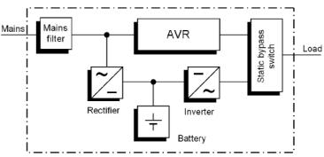
stabilizes the load voltage. As a result, voltage fluctuations in the public utility's mains are reduced to a level which is acceptable for the loads. This is performed without recourse to the internal energy storage, something which in turn has a positive effect on battery availability.
UPS block diagram PROTECT B.
The static bypass switch is activated in the event of a mains failure. The inverter then takes over the voltage supply of the connected loads, in order to prevent the risk of data loss or damage to the loads. PROTECT B. supplies voltage until the battery is discharged, allowing you to shut down your IT system properly and switch it off. The standby time mainly depends on the connected loads. If the mains power supply is back to normal values, the UPS will switch back the loads to mains supply. The battery charger will then recharge the battery.
For safety reasons (as required by German standards, VDE), the mains input in the unit will be disconnected by a two-pole switch in the event of a mains failure. Energy backfeed to the mains and voltage supply to the pins of the mains connector are thus reliably avoided.
Furthermore, additional protective measures ensure effective protection for the data/network interface.
9
3 Safety
3.1General Safety Instructions
Read these operating instructions carefully prior to commissioning of the PROTECT B. UPS and observe the safety instructions!
Only use the unit if it is in a technically perfect condition and always in accordance with its intended purpose, while being aware of safety and danger aspects, and in accordance with the operating instructions! Immediately eliminate any faults which could be detrimental to safety.
The following pictograms are used in these operating instructions to identify dangers and important information:
|
Danger! |
|
Identifies risk of fatal injury to the operator. |
|
Attention! |
|
Identifies risk of injury and risk of damage to the |
|
unit and parts of the unit. |
i |
Information! |
Useful and important information for operating |
|
the UPS. |
3.2Safety Instructions for PROTECT B.
This chapter contains important instructions for the PROTECT B. UPS. These must be followed during assembly, operation and maintenance of the uninterruptible power supply and the batteries.
The UPS carries high voltage. Danger! The unit may only be opened by trained and qualified personnel. Repairs may only be carried out by qualified customer service staff!
10
The output may be live, even if the UPS is not connected to the mains supply, as the UPS has its own internal power supply (battery)!
For health and safety reasons, the unit must be earthed correctly!
PROTECT B. may only be operated with or connected to a 230 Vac mains with protective grounding using a mains connection cable with PE conductor (included in the delivery) that has been tested in accordance with German standards (VDE).
Danger! Risk of burning!
The battery has powerful short-circuit currents. Incorrect connection or isolation faults can lead to melting of the plug connections, sparking potential and severe burns!
The unit has a warning signal that sounds when the battery voltage of PROTECT B. is exhausted or when the UPS is not working in its normal mode.
Observe the following safety instructions to ensure permanent operational safety of and safe work with the UPS:
♦Do not dismantle the UPS! (The UPS does not contain any parts which require regular maintenance. Bear in mind that the warranty will be invalidated if the unit is opened!)
♦Do not install the unit in direct sunshine or in close proximity of heaters!
♦The unit is designed to be installed inside in heated rooms. Never install the UPS in the vicinity of water or in an excessively damp environment!
♦Condensation may occur if the UPS is brought from a cold environment into the room where it is to be installed. The UPS must be absolutely dry prior to start-up. As a result, leave it to acclimatize for at least two hours.
11

♦Never connect the mains input to the UPS output.
♦Ensure that no fluids or foreign bodies can penetrate the UPS!
♦Do not block the air vents of the unit! Keep children away from the unit and ensure that objects are never inserted through the air vents!
♦Do not connect household appliances such as hairdryers to the UPS!
♦The mains connection should be near the unit and easily accessible to facilitate disconnecting the AC input or pulling out the plug!
♦During operation, do not disconnect the mains connection cable from the UPS or from the socket outlet in the building (shockproof socket), otherwise the protective grounding of the UPS and all the loads connected to it will be cancelled.
Danger! Electric shocks!
Even after the mains voltage has been disconnected, the components within the UPS remain connected to the battery and can thus cause electric shocks. It is therefore imperative to disconnect the battery circuit before carrying out any maintenance or repair work!
If it is necessary to replace the battery or carry out maintenance work, this must be done by or under the supervision of a specialist familiar with batteries and the necessary safety precautions!
Only authorised persons are allowed in the vicinity of the batteries!
When replacing the battery/batteries, the following must be observed: Only ever use identical maintenance-free sealed lead batteries with the same data as the original battery/ batteries.
12

Danger! Explosive!
Never throw batteries into open fire. Never open or damage batteries. (Electrolyte may leak out and damage skin and eyes. It may be toxic!)
Batteries can cause electric shocks and high short-circuit currents.
Therefore, take the following safety precautions when working with batteries:
♦Take off watches, rings and other metallic objects!
♦Only use tools with insulated handles!
For personal safety reasons, never switch on the main switch when the mains connector of PROTECT B. is disconnected!
13
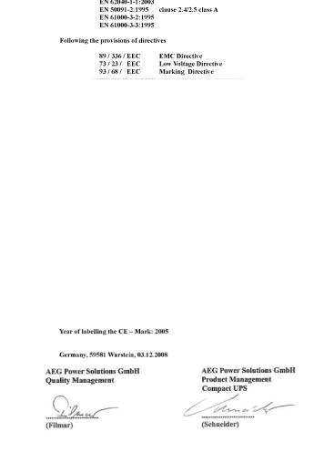
3.3Certification
14
3.4 |
Technical Data |
|
|
Model power |
|
|
PROTECT B. 750 |
750 VA / 500 W |
|
PROTECT B. 1000 |
1000 VA / 700 W |
|
PROTECT B. 1500 |
1500 VA / 1050 W |
|
PROTECT B. 2000 |
2000 VA / 1340 W |
|
PROTECT B. 3000 |
3000 VA / 2100 W |
|
UPS Input |
|
|
Rated output voltage |
220 / 230 / 240 Vac |
|
Input voltage range |
154 / 161 / 168 Vac ± 4% |
|
|
(wide) |
|
|
176 / 184 / 192 Vac ± 4% |
|
|
(standard) until |
|
|
264 / 276 / 288 Vac ± 4% |
|
Frequency (autom. detection) |
50 / 60 Hz ± 5 Hz |
|
|
> 40 Hz (generator mode) |
|
Curr. consumption (full-load) |
|
|
PROTECT B. 750 |
5 A |
|
PROTECT B. 1000 |
8 A |
|
PROTECT B. 1500 |
10 A |
|
PROTECT B. 2000 |
10 A |
|
PROTECT B. 3000 |
16 A |
|
Connection |
IEC power connector |
|
|
(IEC 320) |
|
USP output |
|
|
Rated output voltage / |
220 / 230 / 240 Vac |
|
AVR-technology |
|
|
Rated output voltage in |
± 5 % |
|
battery mode |
|
|
Frequency in battery mode |
50 Hz / 60 Hz ± 0.1 Hz |
15
Output current power (at 230 Vac)
|
PROTECT B. 750 |
|
3.2 A |
|
|
|
|
|
|
PROTECT B. 1000 |
|
4.3 A |
|
|
|
|
|
|
PROTECT B. 1500 |
|
6.5 A |
|
|
|
|
|
|
PROTECT B. 2000 |
|
8.7 A |
|
|
|
|
|
|
PROTECT B. 3000 |
|
13 A |
|
|
|
|
|
|
Transfer time at mains outage |
2-4 ms (typical), |
|
|
||||
|
|
|
|
6 ms max. |
|
|
||
|
|
|
|
13 ms max. |
|
|
||
|
|
|
|
in generator operation |
|
|||
|
Voltage waveform |
|
sinusoidal |
|
|
|||
|
Outlets |
|
|
Non-heating appliance |
|
|||
|
|
|
|
connectors acc. to IEC 320 |
|
|||
|
Overload response |
|
110% for 3 min. / |
|
|
|||
|
at mains operation |
|
150% for 200 ms |
|
|
|||
|
Overload response |
|
110% for 30 s / |
|
|
|||
|
at battery operation |
|
120% for 100ms |
|
|
|||
|
Overheat and short circuit protection Yes |
|
|
|
|
|||
|
Battery |
|
|
|
|
|
|
|
|
Autonomy time at rated load |
5 min. |
|
|
|
|
||
|
|
|
|
Extendable from B.1500 |
|
|||
|
Rated time with external battery packs |
|
|
|
|
|||
|
|
|
|
|
|
|
|
|
|
Number of |
|
|
|
|
|
|
|
|
connected |
Autonomy time at rated load |
|
|
|
|
||
|
battery |
|
|
|
|
|||
|
|
|
|
|
|
|
|
|
|
packs |
|
|
|
|
|
|
|
|
|
1500 VA |
1500 VA |
2000 VA |
2000 VA |
|
3000 VA |
|
|
|
Tower |
Rack |
Tower |
Rack |
|
Tower/Rack |
|
|
|
|
|
|
|
|
|
|
|
1 |
15 min. |
- - - |
15 min. |
- - - |
|
24 min. |
|
|
|
|
|
|
|
|
|
|
|
2 |
30 min. |
30 min. |
27 min. |
27 min. |
|
45 min. |
|
|
|
|
|
|
|
|
|
|
|
3 |
50 min. |
- - - |
40 min. |
- - - |
|
55 min. |
|
|
|
|
|
|
|
|
|
|
|
4 |
65 min. |
65 min. |
50 min. |
50 min. |
|
75 min. |
|
|
|
|
|
|
|
|
|
|
|
Deep discharge protection / |
yes |
|
|
|
|
||
|
Overload protection |
|
|
|
|
|
|
|
16
Recharge time |
3 h (UPS in |
|
(to 90 % of rated capacity) |
standard configuration) |
|
|
7 h (UPS with 1 add. battery |
|
|
pack) |
|
|
12 h (UPS with 2 add. |
|
|
battery packs) |
|
|
18 h (UPS with 3 add. |
|
|
battery packs) |
|
|
24 h (UPS with 4 add. |
|
|
battery packs) |
|
Type |
Sealed, maintenance free, |
|
|
hot swappable (from B.1500) |
|
PROTECT B. 750 |
12 V / 7 Ah x 2 |
|
PROTECT B. 1000 |
12 V / 9 Ah x 2 |
|
PROTECT B. 1500 / B. 1500BP |
12 V / 7 Ah x 4 |
|
PROTECT B. 2000 / B. 2000BP |
12 V / 9 Ah x 4 |
|
PROTECT B. 3000 |
12 V / 5 Ah x 8 |
|
PROTECT B. 3000 BP |
12 V / 5 Ah x 8 x 2 |
|
Communication |
|
|
Interfaces |
USB and RS232 |
|
|
Additionally from |
|
|
PROTECT B.1500: |
|
|
Communication slot |
|
|
for i.e. SNMP as well as |
|
|
input contact for |
|
|
emergency shutdown |
|
Shutdown-Software on CD |
For all typical operating |
|
|
systems, e.g. Windows, |
|
|
Linux, Mac, Unix, FreeBSD, |
|
|
Novell, Sun |
|
Physical data |
|
|
Noise (1 m distance) |
< 45 dB(A) |
|
Operation temperature range |
0°C - 40°C |
|
Humidity |
0 - 90% (without condens.) |
|
Installation height |
up to 1000 m at rated power |
|
17
 Loading...