


PROTECT 1.100
UPS OPERATING INSTRUCTIONS
PROTECT 1.
PROTECT 1.100
PROTECT 1.150
PROTECT 1.200

2

Thank you for deciding to purchase the PROTECT 1. UPS
from AEG Power Supply Systems.
The following safety instructions are an important part of
the operating instructions are will protect you against
problems from operating errors and possible dangers.
Please read these instructions carefully prior to
commissioning!
3

1 Notes on these Operating
Instructions
Duty to provide information
These operating instructions will help you to install and operate
the Uninterruptible Power Supply (UPS), PROTECT 1.100,
PROTECT
corresponding external battery units PROTECT 1.100 BP or
PROTECT 1.BP20, all referred to as PROTECT 1 in the
following, safely and correctly. These operating instructions
contain important information for avoiding dangers.
Please read these instructions carefully prior to
commissioning!
These operating instructions are an integral part of
PROTECT 1.
The owner of this unit is obliged to communicate the full content
of these operating instructions to all personnel transporting or
starting the PROTECT 1 or performing maintenance or any
other work on the unit.
1.150 or PROTECT 1.200 as well as the
Validity
These operating instructions comply with the current technical
specifications of PROTECT 1. at the time of publication. The
contents do not constitute a subject matter of the contract, but
serve for information purposes only.
Warranty and liability
We reserve the right to alter any specifications given in these
operating instructions, especially with regard to technical data
and operation.
Claims in connection with supplied goods must be submitted
within eight days of receiving the goods, along with the packing
slip. Subsequent claims cannot be considered.
The warranty does not apply for damage caused by noncompliance with these instructions (such damage also includes
damage to the warranty seal). AEG will accept no liability for
4

consequential damage. AEG will rescind all obligations such as
warranty agreements, service contracts, etc. entered into by
AEG or its representatives without prior notice in the event of
maintenance and repair work being carried out with anything
other than original AEG parts or spare parts purchased
from AEG.
Handling
PROTECT 1. is designed and constructed so that all necessary
steps for start-up and operation can be performed without any
internal manipulation of the unit. Maintenance and repair work
may only be performed by trained and qualified personnel.
Illustrations are provided to clarify and facilitate certain steps.
If danger to personnel and the unit cannot be ruled out in the
case of certain work, it is highlighted accordingly by pictographs
explained in the safety regulations of chapter 3.
Hotline
If you still have questions after having read these operating
instructions, please contact your dealer or our hotline:
Tel: +49 (0)180 5 234 787
Fax: +49 (0)180 5 234 789
Internet: www.aegpss.de
Copyright
No part of these operating instructions may be transmitted,
reproduced and/or copied by any electronic or mechanical
means without the express prior written permission of AEG.
© Copyright AEG 2007. All rights reserved.
5

Table of Contents
1 Notes on these Operating Instructions .............................4
2 General Information ..........................................................8
2.1 Technology ................................................................8
2.2 System Description..................................................10
2.3 Technical data .........................................................12
3 Safety Regulations..........................................................16
3.1 Important Instructions and Explanations .................16
3.2 Accident Prevention Regulations ............................16
3.3 Qualified Personnel .................................................17
3.4 Safety Instructions for PROTECT 1. .......................17
3.5 CE certificate ...........................................................21
4 Set-up..............................................................................22
4.1 Unpacking and inspection .......................................22
4.2 Transport to installation site.....................................23
4.3 Set-Up......................................................................23
4.4 Overview: Connections, Operating /
Display Elements.....................................................25
4.4.1 Front view...........................................................25
4.4.2 Display ...............................................................26
4.4.3 Rear view (connections): ...................................27
5 Electrical connection .......................................................29
5.1 Safety of personnel..................................................30
5.2 Mains connection (general) .....................................30
5.2.1 Checklist for cable connections .........................30
5.2.2 Connection Cross-Sections and Fuse
Protection...........................................................31
5.3 Mains connection.....................................................32
5.3.1 Preparation for the three-phase mains
connection ....................................................32
5.3.2 Connection of the three-phase input
mains voltage.....................................................32
5.3.3 Preparation of the output cabling.......................33
5.3.4 Connection of the loads .....................................34
5.4 Connection of external battery modules..................34
5.4.1 Connection of the battery cubicle
PROTECT 1.100 BP..........................................35
6

5.4.2 Connection of the battery cubicle PROTECT 1.
BP20 ..................................................................36
5.5 Mechanical blocking of the PROTECT 1.................37
6 Start-Up...........................................................................38
6.1 Operating modes.....................................................39
6.1.1 Normal operation ...............................................39
6.1.2 Battery Operation / Autonomous Operation ......40
6.1.3 Bypass operation ...............................................42
6.1.4 Manual bypass...................................................44
6.1.5 Unit overload......................................................45
7 Interfaces and communication........................................46
7.1 Computer interface RS232......................................46
7.2 Communication Slot ................................................46
7.3 Shutdown and UPS Management Software............46
8 Displays and troubleshooting..........................................48
8.1.1 Signalling ...........................................................48
8.1.2 Overview table of LED displays / acoustic
warning signals ..................................................50
8.2 Faults.......................................................................52
8.2.1 Error Messages..................................................52
9 Parallel Operation ...........................................................54
9.1 Principle of Operation..............................................54
9.2 Set-up / connection of parallel operation board ......55
9.3 Operation of the UPS in a parallel system ..............57
9.3.1 Start-Up..............................................................57
9.3.2 Changes to the parallel system .........................59
10 Maintenance ...................................................................60
10.1 Charging the Battery ...............................................60
10.2 Checks.....................................................................60
10.2.1 Visual check.......................................................60
10.2.2 Checking the battery..........................................61
10.2.3 Fan check ..........................................................61
11 Storage, Dismantling and Disposal.................................62
11.1 Storage ....................................................................62
11.2 Dismantling..............................................................62
11.3 Disposal...................................................................62
12 List of terms ....................................................................63
12.1 Technical terminology .............................................63
7

r
2 General Information
2.1 Technology
PROTECT 1. is an U
Supply (UPS) for essential loads such as small
i
♦ Mains filter with overvoltage protection (appliance
♦ Rectifier section with PFC logic
♦ Separate battery charger with
♦ IGBT inverter for continuous supply of connected loads with
data centres, servers, network components,
telecommunications equipment and similar units. It
consists of:
protection / class D) and mains energy backfeed
protection
(power factor correction unit)
switch mode power supply technology
sinusoidal AC voltage
ninterruptible Powe
♦ Automatic electronic bypass (SBS)
as additional, passive redundancy
SBS = S
♦ Manual bypass for maintenance and
service purposes (with automatic
SBS activation upon actuation)
♦ Control unit
on the basis of digital signal processor technology
tatic Bypass Switch
8
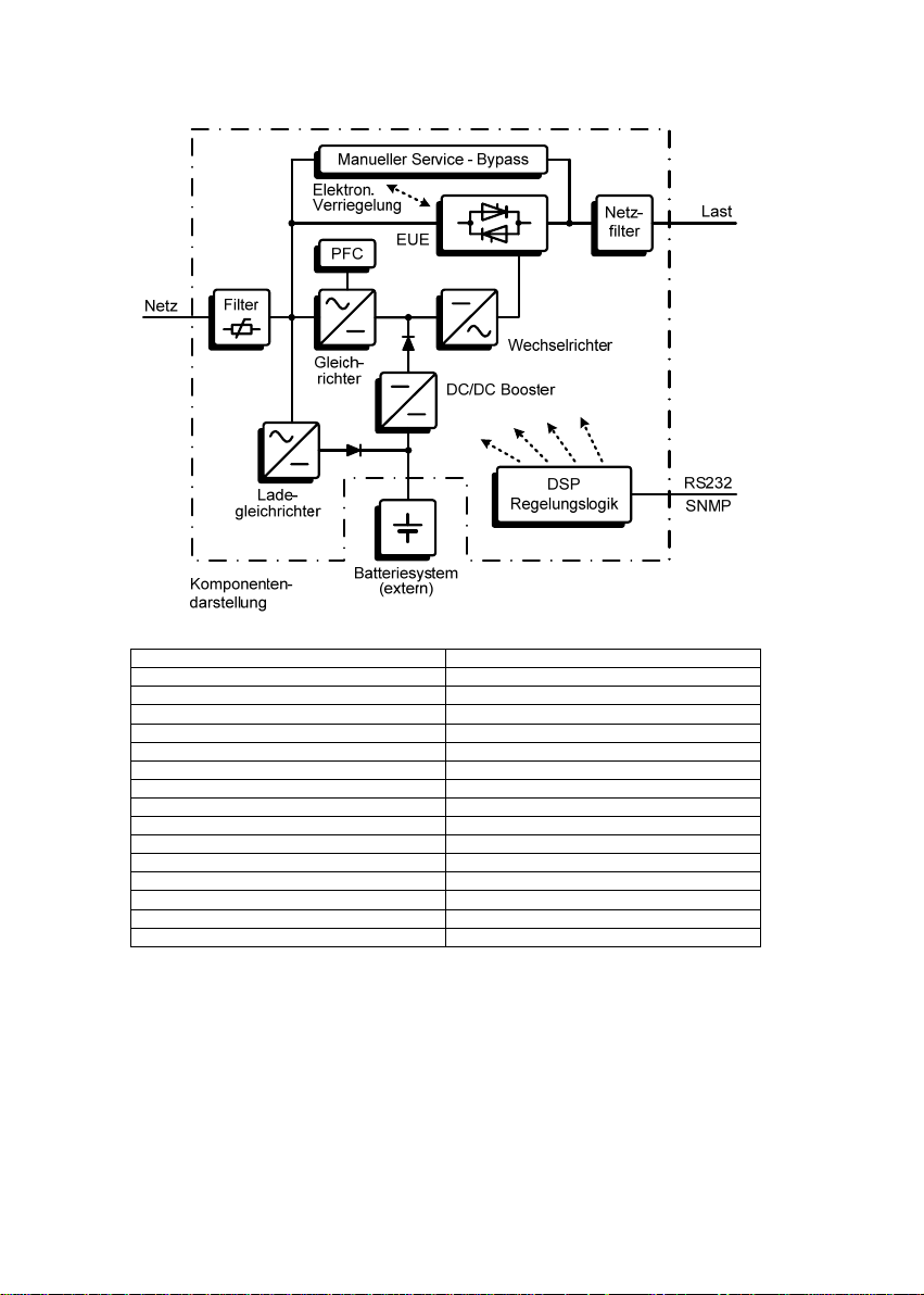
Manueller Service - Bypass Manual service bypass
Elektron. Verriegelung Electronic locking
EUE SBS
PFC PFC
Netzfilter Mains filter
Last Load
Netz Mains
Filter Filter
Gleichrichter Rectifier
Wechselrichter Inverter
DC/ DC Booster DC/DC booster
Ladegleichrichter Battery charger
DSP Regelungslogik DSP control logic
Komponentendarstellung Component diagram
Batteriesystem (extern) Battery system (external)
RS 232 SNMP RS 232 SNMP
9

2.2 System Description
The UPS is connected between the public utility mains and the
loads to be protected.
The power section of the rectifier converts the mains voltage to
DC voltage for supplying the inverter. The circuit technology used
(PFC) enables sinusoidal current consumption and therefore
operation with little system disturbance. A separate, second
rectifier (charging REC set up using switch mode power supply
technology) is responsible for charging or trickle-charging the
battery connected in the intermediate circuit. The configuration of
this charging REC means the harmonic content of the charging
current for the battery is almost zero, which increases the service
life of the battery even more. The inverter is responsible for
converting the DC voltage into a sinusoidal output voltage. A
microprocessor-driven control based on a pulse-width modulation
(PWM) guarantees, in conjunction with digital signal processor
technology and extremely fast pulsating IGBT power
semiconductors of the inverter, a voltage system of the highest
quality and availability on the secured busbar.
In the event of mains faults (such as e.g. current failures), the
voltage continues to be supplied from the inverter to the load
without any interruption. From this point onwards, the inverter
draws its power from the battery instead of the rectifier. Since no
switching operations are necessary, there is no interruption in the
supply to the load.
The automatic electronic bypass serves to increase the reliability
of the supply further, especially in the case of individual systems.
It switches the public mains directly through to the load without
any interruption, e.g. when there is an inverter malfunction. As a
result, the automatic bypass represents an extra passive
redundancy for the load.
An integrated, manually operated bypass unit ensures an
uninterrupted supply to the connected loads in the case of
maintenance and/or service work. The internal electronic part
(with the exception of the metal-clad manual bypass) can be
disconnected via the mains input miniature circuit breakers.
10

The greatest possible supply reliability of connected loads is
attained by the parallel connection of up to max. three
PROTECT 1. UPS systems. The n+x technology thus
guarantees maximum reliability through up to double active
redundancy on the one hand as well as on the other hand the
possibility of increased power with simple redundancy or even
only higher UPS power without any redundancy. The relationship
between the available output power and the degree of active
redundancy can be seen in the following overview:
Parallel system with PROTECT 1.100
Available power
Active
redundancy
degree
Parallel system with PROTECT 1.150
Available power
Active
redundancy
degree
0 10 kVA 20 kVA 30 kVA
1 --- 10 kVA 20 kVA
2 --- --- 10 kVA
0 15 kVA 30 kVA 45 kVA
1 --- 15 kVA 30 kVA
2 --- --- 15 kVA
Number of UPS units
1 2 3
Number of UPS units
1 2 3
Parallel system with PROTECT 1.200
Available power
Active
redundancy
degree
0 20 kVA 40 kVA 60 kVA
1 --- 20 kVA 40 kVA
2 --- --- 20 kVA
Number of UPS units
1 2 3
11

2.3 Technical Data
Type rating
PROTECT 1.100 10000 VA (cos ϕ = 0.7 ind.)
PROTECT 1.150 15000 VA (cos ϕ = 0.7 ind.)
PROTECT 1.200 20000 VA (cos ϕ = 0.7 ind.)
UPS input 3ph~ / N / PE
Rated connection voltage 400 V/ 230 VAC
Voltage range without 304 VAC – 478 VAC ± 3 %
battery operation (rectifier)
176 VAC – 261 VAC VAC ± 3 %
(bypass)
Frequency 50 Hz / 60 Hz
Frequency tolerance range ± 4 Hz
Current consumption at full load (max.)
PROTECT 1.100 13 A (3ph~) / 46 A (bypass)
PROTECT 1.150 19 A (3ph~) / 68 A (bypass)
PROTECT 1.200 25 A (3ph~) / 91 A (bypass)
System disturbance factor λ ≥ 0.95
7000 W
10500 W
14000 W
(autom. detection)
UPS output
Nominal voltage output 220 / 230 / 240 VAC ± 1%
(configuration via
“CompuWatch” software )
Nominal frequency 50 Hz / 60 Hz ± 0.1%
(dependent on mains frequency)
Type of voltage Sine, distortion
≤ 2% THD (linear load)
≤ 6% THD (non-linear load)
Crest factor 3:1
12

Overload behaviour Up to 105% continuous;
with mains supply > 105% – < 130% for 10 min.
130% for 1
s
Following this, automatic,
uninterrupted switchover to
integrated bypass (SBS).
Switch-off after 1 min if overload
continues to be present. (Switch
back if overload decreases = load <
90%)
Overload behaviour with Up to 105% continuous;
battery operation > 105% for 10 s
Short-circuit behaviour 2.5 x I
for 100 ms
N
Battery
Standby times with external standard battery units
Coupled
battery cubicles
1 x PROTECT 1.100 BP 16 / 42 --- --- 5h
2 x PROTECT 1.100 BP 42 / 97 --- --- 7h
3 x PROTECT 1.100 BP 60 / 134 --- --- 10h
1 x PROTECT 1. BP 20 19 / 47 10 / 29 6 / 19 5h
2 x PROTECT 1. BP 20 47 / 103 29 / 68 19 / 47 9h
3 x PROTECT 1. BP 20 78 / 77 47 / 103 34 / 62 13h
4 x PROTECT 1. BP 20 103 / 243 68 / 153 47 / 103 18h
5 x PROTECT 1. BP 20 138 / 312 85 / 202 63 / 138 24h
Standby times (full load / half load) [min.]
PROTECT
1.100
PROTECT
1.150
PROTECT
1.200
Recharging time
to 90% capacity
Nominal DC voltage (intermediate circuit): 240 VDC
Trickle charge voltage: 274 VDC ± 1%
Battery charging current (max.): 4.2 ADC
Type Sealed, maintenance-free
PROTECT 1.100 BP 2x20 blocks 12V 9Ah,
e.g. CSB HR 1234WF2
PROTECT 1.BP20 1x20 blocks 12V 20Ah,
e.g. Panasonic LC-X1220P
13

Communication
Interfaces RS232
Sub-D (9-pin)
Additionally: Communication slot
for expansions (e.g. AS/400 / USB
/ remote signal indicator /
SNMP, …)
Shutdown software on CD “CompuWatch” for all common
operating systems, e.g. Windows,
Linux, Mac, Unix, FreeBSD,
Novell, Sun
General data
Classification VFI SS 111 acc. to IEC 62040–3
Sustained transformer technology
Full load efficiency > 90% / > 88%
(
AC-AC / DC-AC )
Inherent noise (1m distance)
PROTECT 1.100 < 55 dB(A)
PROTECT 1.150 < 60 dB(A)
PROTECT 1.200 < 60 dB(A)
Cooling type Forced air cooling through
variable-speed fans
Operating temperature range 0°C to +40°C
Recommended: +15°C to +25°C
(due to battery system)
Storage temperature range 0°C to +40°C
Relative humidity < 95% (without condensation)
Site altitude Up to 1000 m at nominal output
Use more than 1000 m above sea
level results in the following
reduction in output power:
14

t
r
Housing colour: Blackline
Weight:
PROTECT 1. 100 39 kg
PROTECT 1. 150 55 kg
PROTECT 1. 200 55 kg
PROTECT 1.
PROTECT 1.
Dimensions W x H x D:
PROTECT 1.100/1.150/1.200 260 mm x 717 mm x 670 mm
PROTECT 1.100 BP 260 mm x 717 mm x 670 mm
PROTECT 1.
Directives
The PROTECT 1. meets the product standard EN 50091.
The CE mark on the unit confirms compliance with the EC
outline directives for 73/23 EEC – Low voltage and for 89/336
EEC – Electromagnetic compatibility if the installation
instructions described in the operating instructions are
observed.
For 73/23 EEC low-voltage
directive reference number EN 62040-1-1 : 2003
For 89/336 EMC directive
reference number EN 50091-2 : 1995
EN 61000-3-2 : 1995
EN 61000-3-3 : 1995
i
100 BP 135 kg
BP20 170 kg
BP 20 260 mm x 717 mm x 810 mm
Warning:
This is a product for industrial and commercial
use in the second environment – to preven
malfunctions, restrictions on the installation o
additional measures may be required.
Height(m) 1000 1500 2000 2500 3000
Output
power
100% 95% 90% 85% 80%
15
3 Safety Regulations
3.1 Important Instructions and Explanations
The instructions for operation and maintenance, as well as the
following safety regulations must be complied with to ensure
the safety of personnel as well as the continued availability of
the unit. All personnel installing/dismantling, starting up,
operating or servicing the units must be familiar with and
observe these safety regulations. Only trained and qualified
personnel may perform the work described, using tools,
equipment, test equipment and materials intended for the
purpose and in perfect working condition.
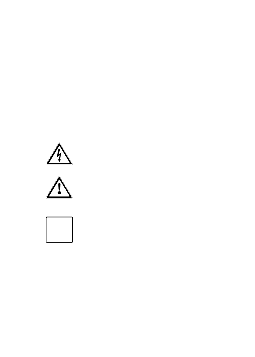
Important instructions are emphasized by the words “Caution”,
“Attention”, “Note” and indented text.
Caution
This symbol identifies all working and operational
procedures requiring absolute compliance to
avoid any danger to persons.
Attention
This symbol identifies all working and operational
procedures requiring absolute compliance to
prevent any damage, irreparable or otherwise, to
the unit and its components.
Note
This symbol identifies technical requirements and
i
additional information requiring the operator's
attention.
3.2 Accident Prevention Regulations
Compliance with the accident prevention regulations valid in the
respective country of use and the general safety regulations in
accordance with IEC 364 is mandatory. The following safety
rules must be observed prior to performing any work on the
PROTECT 1.:
♦ Disconnect the unit from the power supply
♦ Secure the unit against being switched back on
16

♦ Verify that the unit is disconnected from the power supply
♦ Earth and short-circuit the unit
♦ Provide protection by covers or barriers for any
neighbouring live parts
3.3 Qualified Personnel
The PROTECT 1. may only be transported, installed,
connected and serviced by qualified personnel who are familiar
with the pertinent safety and installation regulations. All work
performed must be inspected by responsible expert personnel.
The qualified personnel must be authorised by the responsible
safety officer of the installation to perform the work required.
Qualified personnel is defined as personnel
♦ having completed training and gained experience in the
respective field,
♦ familiar with the pertinent standards, rules and
regulations and accident prevention regulations,
♦ having received instruction on the mode of operation and
operating conditions of the PROTECT 1.,
♦ capable of recognising and preventing dangers.
Regulations and definitions for qualified personnel can be found
in DIN 57105/VDE 0105 Part 1.
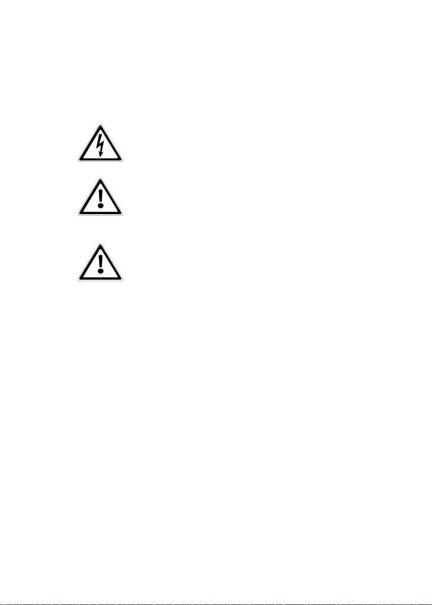
3.4 Safety Instructions for PROTECT 1.
The UPS is live, and the voltage can be
dangerous. The unit may only be installed and
if necessary opened by trained and qualified
personnel. Repairs may only be carried out by
qualified customer service staff!
The output can be live, even when the UPS is not
connected to the mains supply!
For health and safety reasons, the unit must be
earthed correctly!
17
The PROTECT 1. may only be operated with or connected to a
three-phase power system with protective grounding using a
mains connection cable with PE conductor that has been tested
according to German standards (VDE).
Risk of burning!
The battery has powerful short-circuit currents.
Incorrect connection or isolation faults can lead to
melting of the plug connections, sparking potential
and severe burns!
The unit has a warning signal that sounds when
the battery voltage of PROTECT 1. is exhausted
or when the UPS is not working in its normal
mode (see also chapter 6.1 "Signalling”, page 47ff
and the following).
Observe the following safety instructions to
ensure permanent operational safety of and safe
work with the UPS and the battery modules
(special accessories):
♦ Do not dismantle the UPS!
(The UPS does not contain any parts that require regular
maintenance. Bear in mind that the warranty will be
invalidated if the unit is opened!)
♦ Do not install the unit in direct sunshine or in close
proximity of heaters!
♦ The unit is designed to be installed inside in heated
rooms. Never install the housing in the vicinity of water or
in an excessively damp environment!
♦ Condensation may occur if the UPS is brought from a
cold environment into the room where it is to be installed.
The UPS must be absolutely dry prior to start-up. As a
result, leave it to acclimate for at least two hours.
♦ Never connect the mains input and the UPS output!
♦ Ensure that no fluids or foreign bodies can penetrate the
housing!
♦ Do not block the air vents of the unit! Make sure, for
example, that children do not insert any objects in the
ventilation openings!
18
♦ Do not connect household appliances such as hairdryers
to the UPS! Also take care when working with motor
loads. It is essential to avoid back-feeding the inverter,
e.g. if the load is intermittently operated in regenerative
mode.
Danger! Electric shocks!
Even after the mains voltage has been
disconnected, the components within the UPS
remain connected to the battery and can thus
cause electric shocks. It is therefore imperative
to disconnect the battery circuit before carrying
out any maintenance or repair work!
If it is necessary to replace the battery or carry
out maintenance work, this must be done by or
under the supervision of a specialist familiar
with batteries and the necessary safety
precautions!
Only authorized persons are allowed in the
vicinity of the batteries!
When replacing the batteries, the following must be observed:
Only ever use identical, maintenance-free sealed lead batteries
with the same data as the original batteries.
Danger! Explosive!
Never throw batteries into open fire.
Never open or damage batteries. (Electrolyte
may leak out and damage skin and eyes. It may
be toxic!)
Batteries can cause electric shocks and high
short-circuit currents.
Therefore, take the following safety precautions when working
with batteries:
♦ Take off watches, rings and other metallic objects!
♦ Only use tools with insulated handles!
19
Avoid using multiple outlet adapters with a
central on/off switch as protection against
i
Switch OFF the UPS using its main switch if you do not intend
to use it for some time. PROTECT 1. must be switched off
every evening if the electricity supply in your company is
switched off every night. Otherwise, the battery will be
discharged. Frequent and exhaustive discharging of the battery
leads to a shorter service life of the battery and should
therefore be avoided!
uncontrolled load switch-off as well as for
avoiding peak inrush currents.
For personal safety reasons, never switch on
the main switch when the mains connector of
PROTECT 1. is disconnected!
20
 Loading...