


H 500
H 750
HB 750
HBE 800
GB |
Instructions for use |
|
Please read and save these |
|
instructions. |
D |
Gebrauchsanleitung |
|
Bitte lesen und aufbewahren. |
F |
Instruction d'utilisation |
|
Prière de lire et de conserver. |
I |
Istruzioni d'uso |
|
Si prega di leggere le istruzioni e |
|
di conservarle. |
E |
Instrucciones de uso |
|
Lea y conserve estas |
|
instrucciones por favor. |
P |
Instruções de serviço |
|
Por favor leia e conserve em seu |
|
poder. |
NL |
Gebruiksaanwijzing |
DK Brugsanvisning
Vñr venlight at lñse og opbevare.
S Bruksanvisning
Var god läs och tag tillvara dessa instruktioner.
FIN Käyttöohje
Lue ja säilytö
TR Kullanøm kølavuzu
Lütfen okuyun ve saklayin
RUS %)*(+". 5 '& )' & % 4
=SKEPXNVWE TUS\WMWJ M VSZUERMWJ REVWSc^Xb MRVWUXO[Mb
Lees en let goed op deze adviezen.

Introduction |
You demand the best and buy quality ± quality provided by Atlas Copco. |
||||
|
We have built for you a reliable and lasting tool. Working effectively and without |
||||
|
endangering your health is only possible if these instructions for use are being read |
||||
|
carefully before first using this tool. We want to satisfy our customers and would |
||||
|
like you to buy again |
AEG Electric Power Tools from Atlas Copco. |
|||
Technical Data |
|
H 500 |
H 750 |
HB 750 |
HBE 800 |
Nominal power . . . . . . . . . . . . 500 W . . . . . 750 W . . . . . 750 W . . . . . 800 W
Planing width . . . . . . . . . . . . . . 82 mm . . . . 82 mm . . . 102 mm . . . 102 mm
Planing depth . . . . . . . . . . . 0±1,6 mm . 0±2,5 mm . 0±2,0 mm . 0±2,0 mm
Rabbet depth . . . . . . . . . . . . 0±16 mm . . 0±22 mm . . 0±22 mm . . 0±22 mm
No-load speed . . . . . . . . . . 17000 min-1 13000 min-1 13000 min-1 11000 min-1
Weight . . . . . . . . . . . . . . . . . . . 2,5 kg . . . . . 3,5 kg . . . . . 3,7 kg . . . . . 3,8 kg
Advice for your |
Please pay attention to the safety instructions in the attached leaflet! |
|
|||
safety |
Appliances used at many different locations including open air must be connected |
|
|||
|
|
via a current surge preventing switch. |
|
||
|
Always use the protective shields on the machine. |
|
|||
|
Always wear goggles when using the machine. It is recommended to wear gloves, |
|
|||
|
|
sturdy non slipping shoes and apron. |
|
||
|
Sawdust and splinters must not be removed while the machine is running. |
|
|||
|
Do not pierce the motor housing as this could damage the double insulation (use |
|
|||
|
|
adhesives). |
|
|
|
|
Always disconnect the plug from the socket before carrying out any work on the |
|
|||
|
|
machine. |
|
|
|
|
Keep mains lead clear from working range of the machine. Always lead the cable |
|
|||
|
|
away behind you. |
|
|
|
|
Before switching on ensure that protective swing cover moves freely. |
|
|||
|
Only plane with sharp blades and avoid metal (nails, screws). |
|
|||
|
|
When doing stationary planing (not rabbeting) use the guard. |
|
||
|
|
For stationary operation, for trimming small pieces of wood also use push stick. |
|
||
|
|
Only put the planer down after the blades have stopped moving. |
|
||
|
The protective swing cover and the blade drive cover on the side must be easy to |
|
|||
|
|
move to and fro. |
|
|
|
|
The protective swing cover must not be locked open except when the plane is |
|
|||
|
|
beeing used in afixed mounting. |
|
||
|
Operate the protective swing cover only by means of the lever or automatically by |
|
|||
|
|
pressure against the piece being planed. |
|
||
|
In the fixed position, the plane may only be used in the Atlas Copco stationary |
|
|||
|
|
mounting or in the Atlas |
Copco dressing and planing table. |
|
|
|
Do not put the machine down until the blade drive has stopped running. |
|
|||
|
Never reach into the danger area of the plane when it is running. |
|
|||
Measured sound |
|
Typically the A-weighted noise levels of the tool are: |
|
||
value |
|
Sound pressure level = 87 dB (A). Sound power level = 100 dB (A). |
|
||
|
|
Wear ear protectors! |
|
|
|
Measured |
|
Typically the hand-arm vibration is below 2.5 m/s2. |
|
||
vibration value |
|
|
|
|
|
Use |
|
The plane can plane surfaces and rabetts, and bevel and chamfer edges. |
|
||
|
|
Do not use this product in another way as stated for normal use. |
|
|
|
Mains |
|
Connect only to a single-phase AC current supply and only to the mains voltage |
|
||
connection |
|
specified on the rating plate. Connection to sockets without earth protection is |
|
||
|
|
possible as the appliance features protective insulation to DIN 57 740/ VDE 0740 |
|
||
|
|
and CEE 20. Radio suppression complies with the European standard EN 55014. |
|
||
|
|
When fitting the plug, make sure that the brown (live) wire of this appliance is |
|
||
|
|
connected to the plug terminal marked L or coloured red, and the blue (neutral) wire |
|
||
|
|
of this appliance is connected to the plug terminal marked N or coloured black. |
|
||
|
|
Under no circumstances must the wires of this appliance be connected to the earth |
|
||
|
|
terminal of the plug marked either E, with the earth symbol or coloured green or |
|
||
|
|
green/yellow. |
|
|
|
Accessories |
|
The range of accessories with part numbers is shown in our catalogue. |
|
||
|
|
|
|
|
|
ENGLISH |
1 |
|
H 500, H 750, HB 750, HBE 800 |
|
|

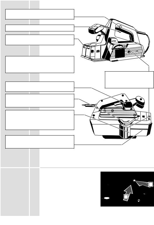
Brief description
Switching on the machine is only possible when pressing the switch±lock (for your safety).
On-/off switch
The planing depth can be infinitely varied by means of the adjusting wheel.
Limited r.p.m. in neutral reduces operating noise ± the r.p.m. are reduced when the machine is not under load.
(only applicable for HBE 800)
Protective swing cover swings back automatically or can be operated by hand using the lever.
Integrated suction channel for connection to a vacuum-cleaner.
Blade drive cover swings back automatically when rabetting.
Hard metal cutters, old±fashioned plane blades
(for rough±planing with adze±marks), and plane blades with grooves for splitting shavings (for easier shavings discharge at greater planing depths), can be fitted into the blade drive shaft.
The old±fashioned plane blades and the grooved plane blades are available as accessories.
The base of the plane is angled so that it can |
|
||
be brought on to the material more accurately, |
|
||
and is fitted with a V±shaped groove for |
|
||
chamfering edges. |
|
Modifications: Text, diagrams and data are correct at the time of |
|
|
|
printing. In the interest of continuous improvement of our products, |
|
|
|
technical specifications are subject to alteration without prior notice. |
|
On-/off switch |
|
For safety reasons this power tool is fitted |
|
|
|
with a switch lock and the On-/Off switch |
|
|
|
cannot be locked in the ºOnº position. |
|
|
|
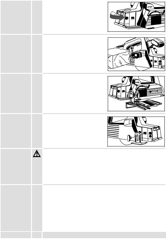
Switching on: |
1 |
|
|
|
|
|
|
Press switch lock (1) and then On-/off |
|
|
|
switch (2). |
2 |
|
|
|
|
|
|
Switching off: |
|
|
|
Release On-/Off switch. |
|
ENGLISH |
2 |
|
H 500, H 750, HB 750, HBE 800 |
Changing the |
Always disconnect the plug from the socket before carrying out any work on the |
plane blade |
machine. |
 As soon as one of the edges of the plane blades becomes blunt please turn plane blade or if worn out replace planer blades (only in pairs!).
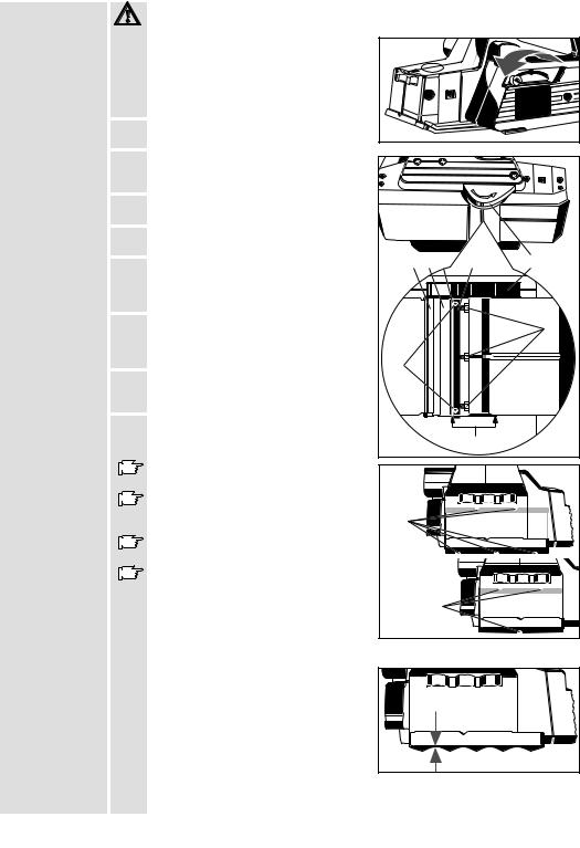
1. Swing the protective cover back using the lever and hold it firmly.
2. Loosen the screws (F) by turning them to the right.
3. Press the blade drive cover (E) down and pull the tension unit (D) out to the side complete with the planer blade.
4. Pull the planer blade out of the tension unit.
5.Clean the tension unit (D) and the blade drive shaft (B).
6. Push the new planer blade all the way in at |
A B C |
D |
E |
the side of the tension unit, making sure |
|
|
|
that the cam on the tension unit fits into |
|
|
|
the groove in the planing blade. |
|
|
|
7. Push the tension unit with the new planer |
|
|
F |
blade into the drive shaft so that the edge |
|
|
|
|
|
|
|
of the planer blade is level with the edge of |
|
|
|
the housing (G). |
H |
|
|
8. Press the tension unit against the drive |
|
|
|
shaft and fasten it by turning the screws |
|
|
|
(F) to the left. |
|
|
|
9. Turn the drive shaft through 180o and |
|
|
|
change the second set of planer blades as |
|
G |
|
described. |
|
|
|
|
|
|
|
Do not move the adjusting screws (H) ± |
HB 750 |
|
|
the tension unit is adjusted in the factory. |
|
|
|
HBE 800 |
|
|
|
When using the grooved planer blades (K), |
|
|
|
|
|
|
|
always use two blades with a different |
K |
|
|
number of grooves. |
|
|
|
Check that the planer blades do not rub |
|
|
against the housing. |
H 500 |
|
Always change both planer blades and |
|
|
H750 |
|
|
both tension units at once. |
|
|
|
K |
Fitting |
Always fit the old±fashioned planing |
|
old±fashioned |
blades complete with the appropriate tension unit. |
|
planing blades |
Fit the planing blades and the tension unit |
|
|
|
|
|
into the blade drive shaft and tigten them |
|
|
with the adjusting screws just enough so |
|
|
that the deepest points on the corrugated |
|
|
blade line up with the plane base. |
|
Adjusting wheel must be set to º0º.
Make sure that the planing blade and the base of the plane are parallel to one another.
Set planing depth to 0.2 mm (max 0.4 mm) with adjusting wheel.
ENGLISH |
3 |
H 500, H 750, HB 750, HBE 800 |
Setting the |
|
With setting wheel. |
planing depth |
|
The notches represent 0,1 mm cutting |
|
|
depth. |
|
|
In setting ºPº (parking) the planer blades |
|
|
are recessed in the housing. |
Sawdust removal |
|
A dust bag or suction hose with adaptor |
(Accessory*) |
|
can be attached to the machine for |
|
|
sawdust removal with an wetand- dry |
|
|
vacuum cleaner. |
|
|
*Not included in standard equipment, |
|
|
available as an accessory. |
Parallel fence |
|
The planing/chamfering width can be set |
(Accessory*) |
|
on the scale after attaching the rip fence. |
|
|
*Not included in standard equipment, |
|
|
available as an accessory. |
Chamfering |
|
The chamfering depth of 0±16 mm can be |
depth gauge |
|
set on the chamfering depth gauge. |
(Accessory*) |
|
|
|
|
*Not included in standard equipment, |
|
|
available as an accessory. |
Advice for |
|
Never reach into the danger area of the plane when it is running. |
operation |
|
Place the front page of the machine on to the worpiece and switch on, before the |
|
|
planer blade touches the workpiese. The selv opening swivel guard closes itself |
|
|
when the machine is lifted, but can laso be effected with lever and then guide evenly |
|
|
over the workpiece. |
|
|
The v±shape notch in the front of the supporting plate ensures safe chamfering of |
|
|
edges. |
|
|
To adjsut cutting depth first set on ºPº. Then adjust to the necessary setting |
|
|
according to required chamfering depth. |
Maintenance |
|
The ventilation slots of the machine must be kept clear at all times. |
|
|
If the shavings discharge is stained with resin, remove it with a cloth soaked in |
|
|
turpentine substitute. |
|
|
In order to guarantee constant readiness for operation, the machine should be |
|
|
checked for worn carbon brushes at one of the AEG after±sales service agencies. |
|
|
Use only AEG accessories and spare parts. Should components need to be |
|
|
replaced which have not been described, please contact one of our AEG service |
|
|
agents (see our list of guarantee/service addresses). |
|
|
If needed, an exploded view of the tool can be ordered. Please state the ten±digit |
|
|
No. as well as the machine type printed on the label and order the drawing at your |
|
|
local service agents or directly at: Atlas Copco Electric Tools GmbH, Postfach 320, |
|
|
D±71361 Winnenden. |
ENGLISH |
4 |
H 500, H 750, HB 750, HBE 800 |

Vorwort |
|
Sie sind anspruchsvoll und kaufen Qualität ± Qualität von Atlas Copco. |
||||
|
|
Wir haben für Sie ein haltbares und möglichst sicheres Elektrowerkzeug gebaut. |
||||
|
|
Effektives und weitgehend gefahrloses Arbeiten ist aber nur möglich, wenn Sie diese |
||||
|
|
Gebrauchsanleitung lesen und danach handeln. Wir wollen, daû Sie sich auch in |
||||
|
|
Zukunft entscheiden für |
|
AEG-Elektrowerkzeuge von Atlas Copco. |
||
Technische |
|
|
H 500 |
H 750 |
HB 750 |
HBE 800 |
Daten |
|
Nennaufnahme |
500 W |
750 W |
750 W |
800 W |
|
|
|||||
|
|
Hobelbreite . . . . . . . . . . . . . . |
. . 82 mm |
. . . . 82 mm |
. . . 102 mm |
. . . 102 mm |
|
|
Spantiefe . . . . . . . . . . . . . . . |
0±1,6 mm |
. 0±2,5 mm |
. 0±2,0 mm |
. 0±2,0 mm |
|
|
Falztiefe . . . . . . . . . . . . . . . . . |
0±16 mm |
. . 0±22 mm |
. . 0±22 mm |
. . 0±22 mm |
|
|
Leerlaufdrehzahl . . . . . . . . |
17000 min-1 |
13000 min-1 |
13000 min-1 |
11000 min-1 |
|
|
Gewicht . . . . . . . . . . . . . . . . . |
. 2,5 kg . . |
. . . 3,5 kg . . |
. . . 3,7 kg . . |
. . . 3,8 kg |
|
|
|
|
|||
Hinweise für |
Sicherheitshinweise der beiliegenden Broschüre beachten! |
|
||||
Ihre Sicherheit |
Steckdosen in Auûenbereichen müssen mit Fehlerstrom-Schutzschaltern |
|||||
|
||||||
|
|
ausgerüstet sein. Das verlangt die Installationsvorschrift für Ihre Elektroanlage. Bitte |
||||
|
|
beachten Sie das bei der Verwendung unseres Gerätes ± sprechen Sie mit Ihrem |
||||
|
|
Elektroinstallateur. |
|
|
|
|
Schutzeinrichtung der Maschine unbedingt verwenden.
Beim Arbeiten mit der Maschine stets Schutzbrille tragen. Schutzhandschuhe, festes und rutschsicheres Schuhwerk und Schürze werden empfohlen.
Späne oder Splitter dürfen bei laufender Maschine nicht entfernt werden.
Gehäuse der Maschine nicht anbohren, da sonst die Schutzisolierung unterbrochen wird (Klebeschilder verwenden).
Vor allen Arbeiten an der Maschine Stecker aus der Steckdose ziehen.
Anschluûkabel stets vom Wirkungsbereich der Maschine fernhalten. Kabel immer nach hinten von der Maschine wegführen.
Vor jeder Inbetriebnahme die Pendelschutzhaube auf Leichtgängigkeit prüfen.
Nur mit scharfen Messern und nie über Metall (Nägel, Schrauben) hobeln.
Die Pendelschutzhaube und der seitliche Messerwellenschutz müssen leicht beweglich sein.
Die Pendelschutzhaube des Hobels darf nur beim Arbeiten in der
Stationäreinrichtung arretiert werden, wenn dafür die Pendelschutzhaube der
Stationäreinrichtung eingesetzt wird.
Schutzhaubenbetätigung nur am Hebel oder automatisch durch das Werkstück.
Der Hobel darf stationär nur in der Atlas Copco±Stationäreinrichtung oder in der Atlas Copco±Abricht± und Hobeleinrichtung betrieben werden.
Maschine erst nach Auslauf der Messerwelle absetzen.
Nicht in den Gefahrenbereich der laufenden Maschine greifen.
Geräusch- |
|
Der A-bewertete Geräuschpegel des Gerätes beträgt typischerweise: |
|
|
meûwerte |
|
Schalldruckpegel = 87 dB (A). |
|
|
|
|
Schalleistungspegel = 100 dB (A). |
|
|
|
|
Gehörschutz tragen! |
|
|
Vibrations- |
|
Die Hand-Arm Vibration ist typischerweise niedriger als 2,5 m/s2. |
|
|
meûwerte |
|
|
|
|
Verwendung |
|
Der Hobel ist geeignet zum Hobeln von Flächen und Falzen und zum Anfasen von |
|
|
|
|
Kanten. |
|
|
|
|
Dieses Gerät darf nur wie angegeben bestimmungsgemäû verwendet werden. |
|
|
Netzanschluû |
|
Nur an Einphasen-Wechselstrom und nur an die auf dem Leistungsschild |
|
|
|
|
angegebene Netzspannung anschlieûen. Anschluû ist auch an Steckdosen ohne |
|
|
|
|
Schutzkontakt möglich, da eine Schutzisolierung nach DIN 57 740/ VDE 0740 bzw. |
|
|
|
|
CEE 20 vorliegt. Die Funkentstörung entspricht der Europanorm EN 55014. |
|
|
Zubehör |
|
|
|
|
|
Das Zubehör mit Bestellnummern ersehen Sie bitte aus unseren Katalogen. |
|
||
|
|
|
|
|
DEUTSCH |
5 |
H 500, H 750, HB 750, HBE 800 |
|
|

Kurzbeschreibung
Ein Einschalten der Maschine ist erst nach Drücken der Einschaltsperre möglich (für Ihre Sicherheit).
Schalterdrücker
Stufenlose Spantiefeneinstellung über Stellrad.
Leerlaufdrehzahlbegrenzung für geräuscharmen Lauf ± die Drehzahl wird bei Entlastung der Maschine vermindert.
(nur bei HBE 800)
Integrierter Absaugkanal zum Anschluû einer Späneabsaugung.
Messerwellenschutz selbstätig zurückschwenkend beim Falzen.
In die Messerwelle können
Hartmetallwendemesser, Rustikalhobelmesser und Hobelmesser mit Spanbrechernuten (für bessere Spanabsaugung bei groûer Spanabnahme) eingesetzt werden.
Rustikalhobelmesser und Hobelmesser mit
Spanbrechernuten sind als Zubehör erhältlich.
Abgeschrägte Hobelsohle zum besseren Ansetzen am Material und mit V±Nut zum Anfasen von Kanten.
Pendelschutzhaube selbstätig zurückschwenkend oder von Hand am Hebel zu betätigen.
|
|
|
Änderungen: Text, Bild und Daten entsprechen dem technischen |
|
|
|
|
Stand zur Zeit des Drucktermins. Änderungen im Sinne der |
|
|
|
|
Weiterentwicklung unserer Produkte sind vorbehalten. |
|
Ein-/Ausschalten |
|
Aus Sicherheitsgründen ist das |
|
|
|
|
Elektrowerkzeug mit einer Einschaltsperre |
|
|
|
|
versehen und der Ein-/Ausschalter läût |
|
|
|
|
sich nicht arretieren. |
|
1 |
|
|
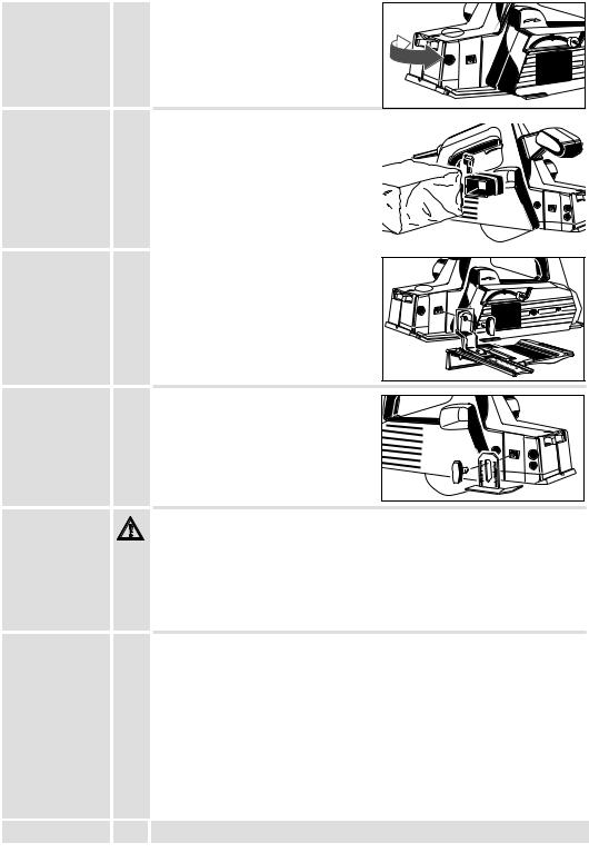
Einschalten: |
|
|
|
|
Einschaltsperre (1) und dann |
2 |
|
|
|
Ein-/Ausschalter (2) drücken. |
|
|
|
|
|
|
|
|
|
Ausschalten: |
|
|
|
|
Ein-/Ausschalter loslassen |
|
|
DEUTSCH |
6 |
|
H 500, H 750, HB 750, HBE 800 |
|

Wechsel der |
Vor allen Arbeiten an der Maschine Stecker aus der Steckdose ziehen. |
Hobelmesser |
|
 Sobald eine Schneide des Hobelmessers stumpf ist, Hobelmesser wenden bzw. nach deren Verschleiû neue Hobelmesser einsetzen (nur paarweise!).
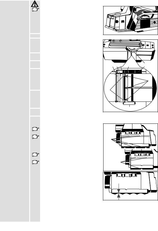
1. Pendelschutzhaube mit dem Hebel zurückschwenken und festhalten.
2. Schrauben (F) nach rechts drehend lösen.
3. Messerwellenschutz (E) nach unten drücken und Spannelement (D) komplett mit Hobelmesser seitlich herausziehen.
4. Hobelmesser aus Spannelement herausziehen.
5.Spannelement (D) und Messerwelle (B) reinigen.
6. |
Neues Hobelmesser seitlich in |
A B C |
D |
E |
|
|
|
||
|
Spannelement bündig einschieben, darauf |
|
|
|
|
achten, daû Nocken des Spannelements |
|
|
|
|
in Hobelmessernut eingreift. |
|
|
|
7. |
Spannelement mit neuem Hobelmesser so |
|
|
F |
|
in die Messerwelle einschieben, daû |
|
|
|
|
Hobelmesserkante und Gehäusekante (G) |
|
|
|
|
bündig abschlieûen. |
H |
|
|
8. Spannelement gegen Messerwelle drücken und verklemmen, hierzu Schrauben (F) linksdrehend festziehen.
9. Messerwelle um 180o verdrehen und  zweiten Hobelmessersatz wie beschrieben G wechseln.
Justierschrauben (H) nicht verstellen, |
HB 750 |
|
Spannelemente sind werksseitig justiert! |
||
HBE 800 |
||
Bei Verwendung von Hobelmessern mit |
||
|
||
Spanbrechernuten (K) immer Messerpaare |
K |
|
mit unterschiedlicher Nutenanzahl |
||
einsetzen. |
|
|
Kontrollieren, daû Hobelmesser nicht am |
H 500 |
|
Gehäuse streifen. |
|
|
Hobelmesser und Spannelemente nur |
H750 |
|
|
|
|
paarweise austauschen! |
K |
|
|
|
Einbau von |
Rustikalhobelmesser nur komplett mit zugehörigen Spannelementen einbauen. |
|
Rustikalhobel- |
Rustikalhobelmesser und Spannelement in |
|
messern |
|
|
Messerwelle einsetzen und mit |
|
|
|
|
|
|
Justierschrauben so einstellen, daû das |
|
|
Wellental des Rustikalhobelmessers mit |
|
|
der Hobelsohle übereinstimmt. |
|
Einstellrad muû hierbei auf º0º stehen.
Darauf achten, daû Hobelmesser und
Hobelsohle parallel sind.
Spantiefe am Einstellrad auf 0,2 mm (max 0,4 mm) einstellen.
DEUTSCH |
7 |
H 500, H 750, HB 750, HBE 800 |

Einstellen der |
Mit Stellrad. |
Spantiefe |
Die Rastung erfolgt in 0,1 mm±Schritten. |
|
In Stellung ºPº (Parkstellung) sind die |
|
Hobelmesser im Gehäuse versenkt. |
Späneabsaugung |
An das Gerät ist ein Staubsack oder mit |
(Zubehör*) |
einem Adapter ein Saugschlauch für |
|
Späneabsaugung mit einem Naûund |
|
Trockensauger oder einem |
|
Haushaltsstaubsauger anschlieûbar. |
|
* Im Lieferumfang nicht enthalten, |
|
empfohlene Ergänzung aus dem |
|
Zubehörprogramm. |
Parallelanschlag |
Die Hobelbreite bzw. Falzbreite ist nach |
(Zubehör*) |
Anbau des Parallelanschlags an der Skala |
|
einstellbar. |
* Im Lieferumfang nicht enthalten, empfohlene Ergänzung aus dem Zubehörprogramm.
Falztiefenan- |
|
Am Falztiefenanschlag kann die Falztiefe |
schlag |
|
von 0 ± 16 mm eingestellt werden. |
(Zubehör*) |
|
|
|
|
* Im Lieferumfang nicht enthalten, |
|
|
empfohlene Ergänzung aus dem |
|
|
Zubehörprogramm. |
Arbeitshinweise |
|
Nicht in den Gefahrenbereich der laufenden Messer greifen! |
|
|
Maschine mit der vorderen Platte auf das Werkstück setzen und einschalten, bevor |
|
|
die Hobelmesser das Werkstück berühren und dann gleichmäûig über das |
|
|
Werkstück führen. |
|
|
Die Pendelschutzhaube darf nur durch das Werkstück oder mit dem Hebel betätigt |
|
|
werden. |
|
|
Die V±Nut in der vorderen Auflageplatte ermöglicht ein sicheres Anfasen von |
|
|
Kanten. |
|
|
Spandicken±Einstellung zuerst auf ºPº stellen. Dann je nach gewünschter |
|
|
Fasenbreite auf erforderlichen Wert einstellen. |
Wartung |
|
Stets die Lüftungsschlitze der Maschine sauber halten. |
|
|
Verharzten Späneauswurf mit einem mit Terpentinersatz getränkten Tuch reinigen. |
|
|
Um eine ständige Betriebsbereitschaft zu gewährleisten, sollte die Maschine einmal |
|
|
jährlich auf abgenutzte Kohlebürsten in einem AEG-Kundendienststützpunkt |
|
|
untersucht werden. |
|
|
Nur AEG Zubehör und Ersatzteile verwenden. Bauteile, deren Austausch nicht |
|
|
beschrieben wurde, bei einer AEG Kundendienststelle auswechseln lassen |
|
|
(Broschüre Garantie/Kundendienstadressen beachten). |
|
|
Bei Bedarf kann eine Explosionszeichnung des Gerätes unter Angabe der |
|
|
Maschinen Type und der zehnstelligen Nummer auf dem Leistungsschild bei Ihrer |
|
|
Kundendienststelle oder direkt bei Atlas Copco Electric Tools GmbH, Postfach 320, |
|
|
D±71361 Winnenden angefordert werden. |
DEUTSCH |
8 |
H 500, H 750, HB 750, HBE 800 |

Introduction |
|
Vous exigez ce qu'il y a de meilleur et vous achetez de la qualité ± la qualité offerte |
||||
|
|
par Atlas Copco. Vous vous êtes dotés d'un outil de qualité durable. Ce n'est qu'en |
||||
|
|
lisant attentivement ces instructions avant d'utiliser l'outil que vous assurerez un |
||||
|
|
travail efficace et sans risque. Nous tenons à satisfaire notre clientèle et nous |
||||
|
|
espérons que vous achèterez encore des |
|
|
||
|
|
|
|
outils électriques AEG d'Atlas Copco . |
||
|
|
|
|
|
|
|
Caractéristiques |
|
|
H 500 |
H 750 |
HB 750 |
HBE 800 |
techniques |
|
Puissance absorbée . . . . . |
. . 500 W . . |
. . . 750 W . . |
. . . 750 W . . |
. . . 800 W |
|
|
Largeur du rabot . . . . . . . . . |
. . 82 mm |
. . . . 82 mm |
. . . 102 mm |
. . . 102 mm |
|
|
Profondeur du copeau . . . 0±1,6 mm |
. 0±2,5 mm |
. 0±2,0 mm |
. 0±2,0 mm |
|
|
|
Profondeur du rainurage . . . |
0±16 mm |
. . 0±22 mm |
. . 0±22 mm |
. . 0±22 mm |
|
|
Régime à vide . . . . . . . . . . |
17000 min-1 |
13000 min-1 |
13000 min-1 |
11000 min-1 |
|
|
Poids . . . . . . . . . . . . . . . . . . . |
. 2,5 kg . . |
. . . 3,5 kg . . |
. . . 3,7 kg . . |
. . . 3,8 kg |
|
|
|
||||
Conseils de |
Respecter les instructions de sécurité se trouvant dans le prospectus ci-joint. |
|||||
sécurité |
Les prises de courant se trouvant à l'extérieur doivent être équipées de disjoncteurs |
|||||
|
|
de protection, répondant ainsi à la prescription de mise en place de votre installation |
||||
|
|
électrique. Veuillez, d'une part, en tenir compte lors de l'utilisation de notre appareil |
||||
|
|
et d'autre part, en parler à votre électricien. |
|
|
||
Il est absolument impératif d'utiliser le dispositif protecteur de la machine.
Toujours porter des lunettes protectrices lorsqu'on travaille avec la machine. Des gants de sécurité et un masque de protection sont recommandés.
Ne jamais enlever les copeaux ni les éclats lorsque la machine est en marche.
Ne pas percer le carter de la machine; ceci pourrait entraîner une détérioration de l'isolation de protection (utiliser des autocollants).
Avant tous travaux sur la machine extraire la fiche de la prise de courant.
Le câble d'alimentation doit toujours se trouver en dehors du champ d'action de la machine. Toujours maintenir le câble d'alimentation à l'arrière de la machine.
Avant chaque mise en service, vérifier la facilité de manoeuvre du capot protecteur.
Ne raboter qu'avec des couteaux affutés et ne jamais passer sur du métal (clous-vis).
Le capot protecteur pendulaire et le protecteur de l'arbre porte±couteau doivent pouvoir bouger facilement.
Le capot protecteur pendulaire ne doit être bloqué que pendant le travail dans le dispositif stationnaire.
Le capot protecteur ne doit être actionné qu'au moyen du levier ou automatiquement par la pièce d'usinage.
Si l'on prévoit un emploi stationnaire, le rabot il ne doit alors être utilisé que dans le dispositif stationnaire Atlas Copco ou dans le dispositif de dégauchissage et de dressage Atlas Copco.
Si l'on prévoit un emploi stationnaire, le rabot il ne doit alors être utilisé que dans le dispositif stationnaire AEG ou dans le dispositif de dégauchissage et de dressage
AEG.
Ne jamais intervenir dans la zone représentant un danger lorsque la machine est en marche.
Mesure de bruit |
|
Les mesures réelles (A) des niveaux de bruit de la machine sont: |
|
|
|
|
Intensité de bruit = 87 dB (A). Niveau de bruit = 100 dB (A). |
|
|
|
|
Toujours porter des casques protecteurs! |
|
|
Valeur de |
|
La vibration de l'avant±bras est en±dessous de 2,5 m/s2. |
|
|
vibration |
|
|
|
|
mesurée |
|
|
|
|
Utilisation |
|
Le rabot permet de raboter le surfaces, les rainures et les quasi±bords. |
|
|
|
|
Comme déjà indiqué, cette machine n'est conçue que pour une utilisation normale. |
|
|
Branchement |
|
Nos machines fonctionnent uniquement sur courant alternatif monophasé. S'assurer |
|
|
secteur |
|
que la tension du réseau correspond effectivement à celle indiquée sur la plaque |
|
|
|
|
signalétique de la machine. Le branchement sur une prise de courant sans mise à |
|
|
|
|
terre est possible du fait de la double isolation selon normes DIN 57 740/VDE 0740 |
|
|
|
|
et CEE 20. Antiparasitage selon normes européennes EN 55014. |
|
|
Accessoires |
|
Consulter nos catalogues qui vous renseignent sur notre programme d'accessoires |
|
|
|
|
avec leur référence. |
|
|
|
|
|
|
|
FRANÇAIS |
9 |
H 500, H 750, HB 750, HBE 800 |
|
|
Description
Pour votre sécurité, la mise en marche de la machine n'est possible qu'après avoir débloqué le verrouillage de mise en marche.
Interrupteur
Réglage en continu de la profondeur du copeau au moyen du bouton sélecteur.
Limitation du régime de marche à vide, assurant un fonctionnement silencieux tout en
diminuant le régime et en ménageant la machine.
(uniquement sur HBE 800)
Capot protecteur pendulaire à rappel automatique ou au moyen du levier.
Canal d'aspiration intégré pour le raccordement d'un dispositif d'aspiration des copeaux.
Protecteur de l'arbre porte±couteaux à rappel automatique lors de rainurage.
Des couteaux à mises en carbure réversibles, ainsi que couteaux rustiques de rabotage et couteaux raboteurs avec rainures brise±copeaux (pour une meilleure aspiration des copeaux et l'enlèvement important de ces derniers) peuvent être mis en place dans l'arbre porte±couteaux. Les couteaux rustiques de rabotage et couteaux raboteurs avec rainures brise±copeaux sont livrables en tant qu'accessoires.
Semelle du rabot biseautée pour garantir une |
|
|
|
meilleure application sur le matériau; la rainure |
Modifications: Les textes, les illustrations et les données |
||
en V quant à elle est prévue pour le |
|||
chanfreinage de bords. |
|
techniques correspondent à la situation au moment de l'impression. |
|
|
Toutes modifications techniques sont réservées dans le cadre du |
||
|
|
développement technique permanent. |
|
Mise en |
Pour des raisons de sécurité, l'outil |
|
|
marche/arrêt |
électrique est doté d'un verrouillage de |
|
|
|
mise en marche et le commutateur de |
|
|
|
mise en marche et d'arrêt ne peut pas |
1 |
|
|
s'enclencher. |
|
|
|
Marche: |
|
2 |
|
appuyer sur le blocage de sécurité puis |
||
|
sur l'interrupteur marche/ arrêt. |
|
|
|
Arrêt: |
|
|
|
lâcher l'interrupteur marche/arrêt. |
|
|
FRANÇAIS |
10 |
H 500, H 750, HB 750, HBE 800 |
Remplacement |
Avant tous travaux sur la machine extraire la fiche de la prise de courant. |
|
||
des couteaux |
Quand une lame du couteau raboteur est |
|
|
|
raboteurs |
émoussée, tourner le couteau raboteur ou, |
|
|
|
|
lorsque celui-ci est usé, monter un |
|
|
|
|
nouveau jeu de coteaux (monter toujours |
|
|
|
|
un jeu de couteaux complet. |
|
|
|
1. Procéder au rappel du capot protecteur |
|
|
|
|
|
pendulaire au moyen du levier et le |
|
|
|
|
maintenir. |
|
|
|
2. Déserrer les vis (F) en tournant vers la droite. |
|
|
||
3. Appuyer le protecteur de l'arbre |
|
|
|
|
|
porte±couteaux (E) vers le bas et extraire |
|
|
|
|
latéralement l'élément de tension (D) |
|
|
|
|
ensemble avec les couteaux raboteurs. |
|
|
|
4. Sortir les couteaux raboteurs hors de |
|
|
|
|
|
l'élément de tension. |
|
|
|
5. Nettoyer l'élément de tension (D) et l'arbre |
A B C |
D |
E |
|
|
porte±couteaux (B). |
|||
|
|
|
|
|
6. Introduire latéralement et à fleur un |
|
|
|
|
|
nouveau couteau raboteur dans l'élément |
|
|
|
|
de tension tout en veillant à ce que la |
|
|
F |
|
came de ce dernier s'enclenche |
|
|
|
|
convenablement dans la rainure du |
|
|
|
|
couteau raboteur. |
H |
|
|
7. Faire glisser l'élément de tension avec |
|
|
||
|
|
|
||
|
couteau raboteur dans l'arbre |
|
|
|
|
porte±couteaux de façon à ce que le bord |
|
|
|
|
du couteau raboteur et celui du carter (G) |
|
|
|
|
coïncident bien à fleur. |
|
G |
|
8. |
|
|
|
|
Appuyer l'élément de tension contre l'arbre porte±couteaux et le bloquer en serrant |
||||
|
les vis (F) vers la gauche. |
|
|
|
9. Décaler l'arbre porte±couteaux de 180oet remplacer le deuxième jeu de couteaux |
||||
|
raboteurs comme indiqué précédemment. |
HB 750 |
|
|
|
Ne pas dérégler les vis d'ajustage (H). Les |
|
|
|
|
éléments de tension sont ajustés en usine! |
HBE 800 |
|
|
|
Lorsqu'on utilise des couteaux raboteurs |
|
|
|
|
avec rainures brise±copeaux (K), toujours |
K |
|
|
|
mettre en place des jeux de deux |
|
|
|
|
|
|
|
|
|
couteaux pourvus d'un nombre différent de |
|
|
|
|
rainures. |
H 500 |
|
|
|
S'assurer que le couteau raboteur ne frotte |
|
|
|
|
pas contre le carter. |
H750 |
|
|
|
Toujours remplacer les couteaux raboteurs |
K |
|
|
|
par jeu de deux, il en est même pour les |
|
|
|
|
éléments de tension! |
|
|
|
Montage des |
Ne monter les couteaux rustiques de |
|
|
|
couteaux |
rabotage que complets, c'est±à±dire avec |
|
|
|
rustiques de |
les éléments de tension. |
|
|
|
rabotage |
Introduire les couteaux rustiques de |
|
|
|
|
rabotage et l'élément de tension dans |
|
|
|
|
l'arbre porte±coteaux et ajuster à l'aide |
|
|
|
|
des vis d'ajustage de façon à ce que le |
|
|
|
|
creux de la vague du couteau rustique de |
|
|
|
|
rabotage coincide avec la semelle du rabot. |
|
|
|
La roue de réglage doit se trouver en position º0º.
Veiller à ce que les couteaux raboteurs et la semelle du rabot soient bien parallèles.
Régler la profondeur de coupe sur 0,2 mm (0,4 mm max.) à l'aide de la roue de réglage.
FRANÇAIS |
11 |
H 500, H 750, HB 750, HBE 800 |
Réglage de la |
Avec le bouton gradué. |
profondeur du |
Chaque graduation correspond à 0,1 mm. |
copeau |
En position ºPº les couteaux ne débordent |
|
plus de la carcasse de la machine. |
Aspiration des |
Un sac collecteur de poussière ou un |
|
|
copeaux |
tuyau d'aspiration muni d'un adaptateur |
|
|
(accessoire*) |
prévu pour l'aspiration des copeaux |
|
|
|
peuvent être raccordés à un aspirateur ou |
|
|
|
à un aspirateur ménager. |
|
|
|
*Ces pièces ne font pas partie de la |
|
|
|
livraison. Il s'agit là de compléments |
|
|
|
proposés pour votre machine et énumérés |
|
|
Guide parallèle |
dans le catalogue d'accessoires. |
|
|
|
|
||
La largeur de rabotage et de feuillurage |
|||
(accessoire*) |
est réglable à l'échelle graduée après |
||
|
montage du guide parallèle. |
||
*Ces pièces ne font pas partie de la livraison. Il s'agit là de compléments proposés pour votre machine et énumérés dans le catalogue d'accessoires.
Guide pour |
On peut régler la profondeur de feuillure |
|
feuillures |
de 0±16 mm sur le guide pour feuillures. |
|
(accessoire*) |
|
|
|
*Ces pièces ne font pas partie de la |
|
|
livraison. Il s'agit là de compléments |
|
|
proposés pour votre machine et énumérés |
|
|
dans le catalogue d'accessoires. |
|
Conseils |
Ne pas mettre la main dans la zone dangereuse des coteaux! |
|
pratiques |
Apposer la semelle avant sur la pièce à raboter, mettre la machine en marche avant |
|
|
||
|
que les couteaux ne rentrent en contact avec la pièce, avancer sans à±coup le rabot |
|
|
sur la pièce. Le carter de protection ne peut être manoeuvré qu'à la main avec le |
|
|
levier ou par la pièce. |
|
|
La rainure en V sur la semelle avant permet le chanfreinage. |
|
|
Régler le rabot à la position ºPº, puis suivant la largeur de chanfrein désirée, régler à |
|
|
la dimension souhaitée. |
|
Entretien |
Tenir toujours propre les orifices de ventilation de la partie moteur. |
|
|
Si le dispositif d'éjection des copeaux est encrassé par la résine, le nettoyer avec un |
|
|
chiffon imbibé de térébenthine. |
|
|
Afin de garantir une disponibilité de service permanente, il est recommandé de faire |
|
|
contrôler une fois par an les balais (charbons) auprès d'un service après±vente |
|
|
AEG. |
|
|
N'utiliser que des pièces et accessoires AEG. Pour des pièces dont l'échange n'est |
|
|
pas décrit, s'adresser de préférence aux stations |
de service après-vente AEG (voir |
|
brochure Garantie/Adresses des stations de service après-vente). |
|
|
Si besoin est, une vue éclatée de l'appareil peut être fournie. S'adresser, en |
|
|
indiquant bien le numéro à dix chiffres porté sur la plaque signalétique, à votre |
|
|
station de service après±vente (voir liste jointe) ou directement à Atlas Copco |
|
|
Electric Tools GmbH, B.P. 320, D±71361 Winnenden. |
|
FRANÇAIS |
12 |
H 500, H 750, HB 750, HBE 800 |

Premessa |
Lei è decisamente esigente e per questa ragione acquista solo prodotti di qualità. |
|||
|
Qualità che la Atlas Copco è perfettamente in grado di garantirLe. Abbiamo |
|||
|
realizzato proprio per Lei un utensile che sia il più possibile affidabile e sicuro. Ora |
|||
|
tocca a Lei. Perchè anche il Suo lavoro sia sicuro e di ottima qualità, La preghiamo |
|||
|
di voler leggere attentamente le istruzioni per l'uso. E' nostro desiderio, infatti, che |
|||
|
anche in futuro acquisti utensili elettrici AEG della Atlas Copco. |
|
||
|
|
|
|
|
Dati tecnici |
H 500 |
H 750 |
HB 750 |
HBE 800 |
Potenza assorbita . . . . . . . . . 500 W . . . . . 750 W . . . . . 750 W . . . . . 800 W Larghezza piallatura . . . . . . . . 82 mm . . . . 82 mm . . . 102 mm . . . 102 mm
Regolazione profonditá
piallatura . . . . . . . . . . . . . . . 0±1,6 mm . 0±2,5 mm . 0±2,0 mm . 0±2,0 mm
Profonditá di battuta . . . . . . 0±16 mm . . 0±22 mm . . 0±22 mm . . 0±22 mm Numero di giri a vuoto . . . . 17000 min-1 13000 min-1 13000 min-1 11000 min-1 Peso . . . . . . . . . . . . . . . . . . . . 2,5 kg . . . . . 3,5 kg . . . . . 3,7 kg . . . . . 3,8 kg
Norme di |
Si prega di leggere con attenzione le istruzioni riguardanti la sicurezza, nel volantino |
|
||
sicurezza |
|
allegato. |
|
|
|
Gli apparecchi mobili usati all'aperto devono essere collegati interponendo un |
|
||
|
|
interruttore di sicurezza per guasti di corrente. |
|
|
|
Usare sempre il dispositivo di protezione dell'apparecchio. |
|
||
|
Durante l'uso dell'apparecchio utilizzare sempre gli occhiali di protezione. Inoltre si |
|
||
|
|
consiglia di usare sistemi di protezione per la respirazione e per l'udito, oltre ai guanti |
|
|
|
|
di protezione. |
|
|
|
Non rimuovere trucioli o schegge mentre l'utensile è in funzione. |
|
||
|
Evitare di forare la carcassa dell'utensile per non danneggiare l'isolamento. |
|
||
|
|
(Utilizzare placchette adesive). |
|
|
|
Prima di effettuare qualsiasi lavoro sulla macchina togliere la spina dalla presa di |
|
||
|
|
corrente. |
|
|
|
Tenere sempre lontano il cavo di collegamento dall'area di lavoro dell'attrezzo. |
|
||
|
Prima dell'uso accertarsi che la calotta di protezione sia correttamente posizionata, |
|
||
|
|
delicamente, una rapida prova. |
|
|
|
Piallare solo con lame affilate e mai su metalli (chiodi, viti). |
|
||
|
La cuffia di protezione oscillante e la protezione lama laterale devono essere |
|
||
|
|
facilmente agibili. |
|
|
|
La cuffia di protezione oscillante puó essere bloccata solamente durante la fase di |
|
||
|
|
lavoro stazionario. |
|
|
|
La cuffia di protezione dovrá essere fissata solo tramite l'apposita leva o |
|
||
|
|
automaticamente premendo contro il pezzo da lavorare. |
|
|
|
La pialla puó essere utilizzata anche per lavori stazionari usando solo il supporto da |
|
||
|
|
banco Atlas Copco o il dispositivo di piallatura Atlas Copco. |
|
|
|
Non deporre la macchina fino a che la lama non si sia fermata. |
|
||
|
Non entrare nel raggio d'azione dell'utensile mentre è in funzione. |
|
||
Livello di |
|
La misurazione A del livello di rumorosità di un utensile è di solito: |
|
|
rumorosità |
|
Livello di rumorosità = 87 dB (A). Potenza della rumorosità = 100 dB (A). |
|
|
|
|
Utilizzare le protezioni per l'udito! |
|
|
Livello di |
|
Le vibrazioni sull'elemento mano-braccio di solito sono inferiori a 2.5 m/s2. |
|
|
vibrazione |
|
|
|
|
Possibilità' di |
|
La pialla lavora su superfici piane, battute e a bordo. |
|
|
utilizzo |
|
Utilizzare il prodotto solo per l'uso per cui è previsto. |
|
|
Collegamento |
|
Alimentazione dell'utensile: corrente alternata monofase. Importante: la tensione |
|
|
alla rete |
|
della rete deve corrispondere a quella riportata sulla targhetta dell'utensile. Il |
|
|
|
|
collegamento é possibile anche con prese non munite di contatto di protezione: é |
|
|
|
|
previsto infatti un isolamento di protezione conforme a norme DIN 57740/VDE 0740 |
|
|
|
|
(CEE 20). La schermatura contro i radiodisturbi é conforme alla norma |
|
|
|
|
europea EN 55014. |
|
|
Accessori |
|
Consultate il nostro catalogo per trovare l 'accessorio più adatto ed il relativo numero |
|
|
|
|
di ordinazione. |
|
|
|
|
|
|
|
ITALIANO |
13 |
H 500, H 750, HB 750, HBE 800 |
|
|
Breve indicazione
La messa in funzione è possibile solamente dopo aver premuto l'interruttore di sicurezza.
Interruttore
Regolazione continua della profonditá di piallatura tramite rotella.
Limitato numero dei giri per un funzionamento silenzioso. Il numero dei giri viene ridotto quando la macchina non é sotto carico.
(solo per HBE 800)
Canalina integrata di aspirazione per attaco aspiratrucioli.
La protezione albero portalame scatta automaticamente indietro sfalzando sullo spigolo.
Nell'albero porta lame possono essere inserite la lama di piallatura, la lama rustica e la lama con scanalature rompitruciolo (per una migliore aspirazione dei trucioli durante piallature profonde).
La piastra di piallatura é smussata al fune di aderire meglio al materiale e tramite la scanalatura a V, per trattare i bordi.
La cuffia di protezione oscillante scatta automaticamnete o puó essere azionata a mano tramite la leva.
Accensione±
Spegnimento
Modifiche: Testo, figure e dati corrispondono allo standard tecnico aggiornato all'epoca della stampa. Ci riserviamo pertanto eventuali modifiche tecniche dovute all'ulteriore sviluppo dei nostri prodotti.
 Per motivi di sicurezza, questo utensile elettrico é dotato di pulsante d'arresto.
Accensione:
Agire sul dispositivo di sicurezza contro l'inserimento involontario, e poi sull'interruttore.
Fermo:
lasciare libero l'interruttore.
1 |
2 |
ITALIANO |
14 |
H 500, H 750, HB 750, HBE 800 |
 Loading...