


X91384MIO |
IT |
CAPPA |
LIBRETTO ISTRUZIONI |
3 |
X92384MIO |
EN |
COOKER HOOD |
USER MANUAL |
12 |
|
FR |
HOTTE DE CUISINE |
MODE D'EMPLOI |
21 |
|
DE |
DUNSTABZUGSHAUBE |
BEDIENUNGSANLEITUNG |
30 |
|
NL |
AFZUIGKAP |
GEBRUIKSAANWIJZING |
39 |
|
ES |
CAMPANA |
MANUAL DE INSTRUCCIONES |
48 |
|
PT |
EXAUSTOR |
MANUAL DE INSTRUÇÕES |
57 |
|
TR |
OCAK DAVLUMBAZ |
KULLANIM KILAVUZU |
66 |
PER RISULTATI PERFETTI
Grazie per aver scelto di acquistare questo prodotto AEG. Lo abbiamo creato per fornirvi prestazioni impeccabili per molti anni, grazie a tecnologie innovative che vi semplificheranno la vita - funzioni che non troverete sui normali elettrodomestici. Vi invitiamo di dedicare qualche minuto alla lettura per sapere come trarre il massimo dal vostro elettrodomestico.
ACCESSORI E PRODOTTI DI CONSUMO
All'interno del webshop AEG troverete tutto ciò che vi serve per fare in modo che i vostri elettrodomestici AEG siano sempre perfettamente puliti e funzionanti. Non mancano inoltre una vasta gamma di accessori studiati e realizzati conformemente agli elevati standard qualitativi che vi aspettate: pentole, scolaposate, portabottiglie e sacchi biancheria delicati...
Visit the webshop at:
www.aeg-electrolux.com/shop
4 IT - CONSIGLI E SUGGERIMENTI/CARATTERISTICHE
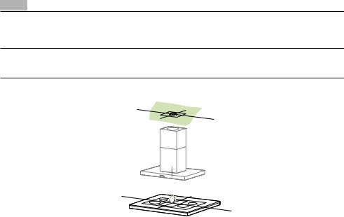
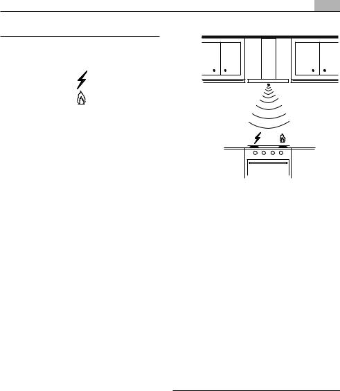
IT - CONSIGLI E SUGGERIMENTI - Questo libretto di istruzioni per l'uso è previsto per più versioni dell' apparecchio. É possibile che siano descritti singoli particolari della dotazione, che non riguardano il Vostro apparecchio. Il produttore declina qualsiasi responsabilità per danni dovuti ad installazione non corretta o non conforme alle regole dell’arte. La distanza minima di sicurezza tra il Piano di cottura e la Cappa deve essere di 650 mm. Verificare che la tensione di rete corrisponda a quella riportata nella targhetta posta all’interno della Cappa. Per Apparecchi in Classe Ia accertarsi che l’impianto elettrico domestico garantisca un corretto scarico a terra. Collegare la Cappa all’uscita dell’aria aspirata con tubazione di diametro pari o superiore a 120 mm. Il percorso della tubazione deve essere il più breve possibile. Non collegare la Cappa a condotti di scarico dei fumi prodotti da combustione (caldaie, caminetti, ecc.). Nel caso in cui nella stanza vengano utilizzati sia la Cappa che apparecchi non azionati da energia elettrica (ad esempio apparecchi utilizzatori di gas), si deve provvedere ad una aerazione sufficiente dell’ambiente. Se la cucina ne fosse sprovvista, praticare un’apertura che comunichi con l’esterno, per garantire il richiamo d’aria pulita. La Cappa è stata progettata esclusivamente per uso domestico, per abbattere gli odori della cucina. Non fare mai uso improprio della Cappa. Non lasciare fiamme libere a forte intensità sotto la Cappainfunzione.Regolaresemprelefiammeinmododaevitareunaevidentefuoriuscitalateraledellestesserispettoalfondodellepentole.Controllarelefriggitrici durante l’uso: l’olio surriscaldato potrebbe infiammarsi. Non preparare alimenti flambè sotto la cappa da cucina; pericolo d'incendio. Questo apparecchio non deve essere utilizzato da persone (bambini inclusi) con ridotte capacità psichiche, sensoriali o mentali, oppure da persone senza esperienza e conoscenza, a meno che non siano controllati o istruiti all’uso dell’apparecchio da persone responsabili della loro sicurezza. I bambini devono essere supervisionati per assicurarsi che non giochino con l’apparecchio. Prima di procedere a qualsiasi operazione di manutenzione, disinserire la Cappa togliendo la spina elettrica o spegnendo l’interruttore generale. Effettuare una scrupolosa e tempestiva manutenzione dei Filtri secondo gli intervalli consigliati (Rischio di incendio), Filtri antigrasso Z Sono lavabili anche in lavastoviglie, e necessitano di essere lavati ogni 2 mesi circa di utilizzo o più frequentemente, per un uso particolarmente intenso - Filtri antiodore al Carbone attivo W Il Filtro antiodore al Carbone attivo non è lavabile e non è rigenerabile, va sostituito ogni 4 mesi circa di utilizzo o più frequentemente, per un uso particolarmente intenso. Per la pulizia delle superfici della Cappa è sufficiente utilizzare un panno umido e detersivo liquido neutro. Il simbolo  sul prodotto o sulla confezione indica che il prodotto non deve essere considerato come un normale rifiuto domestico, ma deve essere portato nel punto di raccolta appropriato per il riciclaggio di apparecchiature elettriche ed elettroniche. Provvedendo a smaltire questo prodotto in modo appropriato, si contribuisce a evitare potenziali conseguenze negative per l’ambiente e per la salute, che potrebbero derivare da uno smaltimento inadeguato del prodotto. Per informazioni più dettagliate sul riciclaggio di questo prodotto,
contattare l’ufficio comunale, il servizio locale di smaltimento rifiuti o il negozio in cui è stato acquistato il prodotto.
Collegare la Cappa all’Alimentazione di Rete interponendo un Interruttore bipolare con apertura dei contatti di almeno 3 mm. Attenzione: Prima di installare la Cappa, togliere le pellicole di protezione (bianca e trasparente).
CARATTERISTICHE
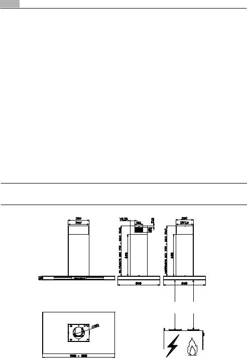
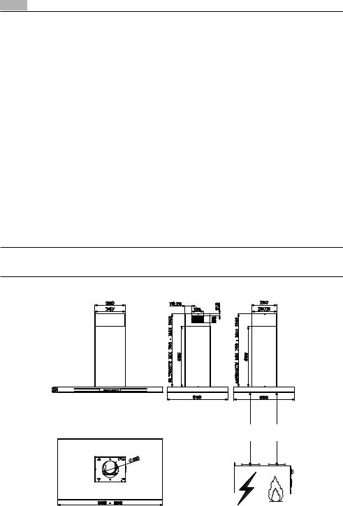
Ingombro
IT - CONSIGLI E SUGGERIMENTI/CARATTERISTICHE |
5 |
|
|
|
|
|
|
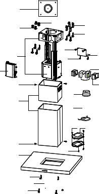
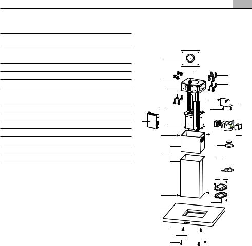
Componenti |
|
Rif.Q.tà |
Componenti di Prodotto |
||
|
1 |
1 |
Corpo Cappa completo di: Comandi, |
|
|
|
|
|
Luce, Filtri |
|
2 |
1 |
Camino telescopico formato da: |
|
|
2.1 |
1 |
Camino superiore |
|
|
2.2 |
1 |
Camino inferiore |
|
|
7.1 |
1 |
Traliccio telescopico completo di Aspi- |
|
|
|
|
|
ratore, formato da: |
|
7.1a1 |
Traliccio superiore |
||
7.1b1 |
Traliccio inferiore |
|||
9 |
1 |
Flangia di riduzione ø 150-120 mm |
||
10 |
1 |
Flangia con Valvola ø 150 |
||
14.12 |
Prolunga Raccordo Uscita Aria |
|||
15 |
1 |
Raccordo Uscita Aria |
||
24 |
1 |
Scatola connessioni |
||
25 |
|
Fascette stringitubo (non incluse) |
||
50 |
1 |
Gruppo Scheda di Controllo |
||
|
|
|
||
Rif.Q.tà |
Componenti di Installazione |
|||
7.3 |
1 |
Staffa fissaggio Raccordo Filtrante |
||
11 |
4 |
Tasselli ø 10 |
||
12c 8 |
Viti 2,9 x 6,5 |
|||
12e 4 |
Viti 2,9 x 9,5 |
|||
12f 2 |
Viti M4 x 80 |
|||
12g 4 |
Viti M6 x 80 |
|||
12h 4 |
Viti 5,2 x 70 |
|||
12q 4 |
Viti 3,5 x 9,5 |
|||
21 |
1 |
Dima di foratura |
||
22 |
8 |
Rondelle ø 6,4 |
||
23 |
4 |
Dadi M6 |
||
|
|
|
|
|
|
|
Q.tà |
Documentazione |
|
|
|
|
1 |
Libretto Istruzioni |
|
|
|
|
|
|
|
|
|
|
|
|
|
||
|
|
|
|
|
|
|
|
|
|
|
|
|
|
|
|
|
|
|
|
|
|
|
|
|
|
|
|
|
|
|
|
|
|
|
|
|
|
|
|
|
|
|
||
|
|
|
|
|
|
|
|
|
|


6 IT - INSTALLAZIONE
INSTALLAZIONE
Foratura Soffitto/Mensola e Fissaggio Traliccio
•Con l’ausilio di un Filo a piombo riportare sul Soffitto/Mensola di supporto il centro del Piano di
Cottura.
•Appoggiare al Soffitto/Mensola la Dima di Foratura 21 in dotazione, facendo coincidere il suo centro al centro proiettato e allineando gli assi della Dima agli assi del Piano di Cottura.
•Segnare i centri dei Fori della Dima.
•Forare i punti seguenti:
•Soffitto in Calcestruzzo massiccio: secondo Tasselli per Calcestruzzo impiegati.
•Soffitto in Laterizio a camera d’aria, con spessore resistente di 20 mm: ø 10 mm (inserire subito i Tasselli 11 in dotazione).
•Soffitto in Travatura di Legno: secondo Viti per Legno impiegate.
•Mensola in Legno: ø 7 mm.
•Passaggio del Cavo elettrico di Alimentazione: ø 10 mm.
•Uscita Aria (Versione Aspirante): secondo diametro del collegamento alla Tubazione di Evacuazione Esterna.
•Avvitare, incrociandole e lasciando 4-5 mm dal soffitto, due viti:
•per Calcestruzzo massiccio, Tasselli per Calcestruzzo, non in dotazione.
•per Laterizio a camera d’aria, con spessore resistente di 20 mm circa, Viti 12h, in dotazione.
•per Travatura di legno, Viti per legno, non in dotazione.
•per Mensola in Legno, viti 12g con Rondelle 22 e Dadi 23, in dotazione.
IT - INSTALLAZIONE 7
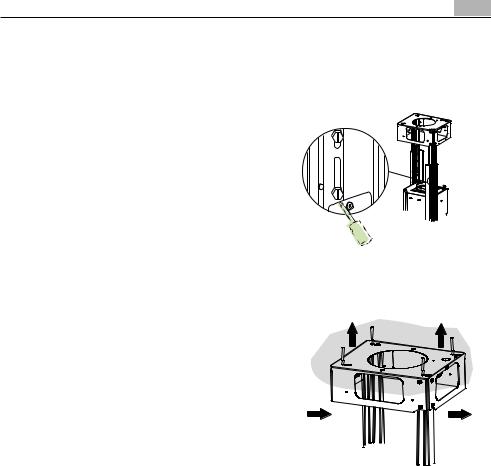
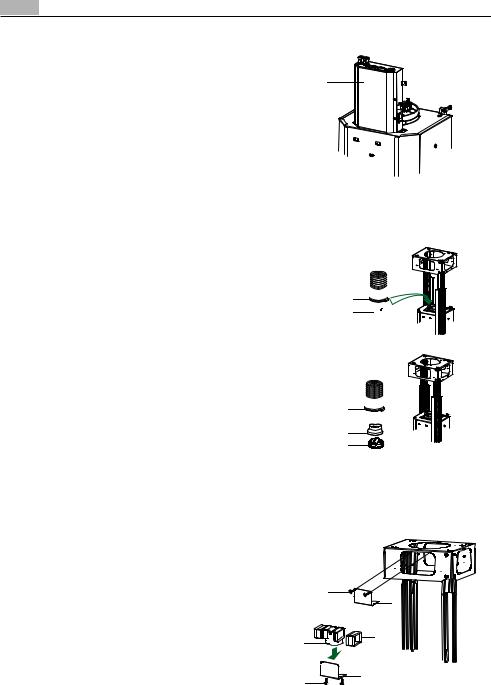
FISSAGGIO TRALICCIO
•Svitare le due viti che fissano il camino inferiore e sfilarlo dal traliccio (dalla parte inferiore).
•Svitare le due viti che fissano il camino superiore e sfilarlo dal traliccio (dalla parte superiore).
Nel caso in cui si voglia regolare l’altezza del traliccio procedere come segue:
•Svitare le viti metriche che uniscono le due colonne, poste ai lati del traliccio;
• Regolare l’altezza desiderata del traliccio e riavvitare le viti precedentemente tolte;
• Inserire il camino superiore dall’ alto e lasciarlo libero sul traliccio;
• Sollevare il traliccio, incastrare le asole sulle viti e scorrere fino a battuta;
•Stringere le due viti e avvitare le altre due in dotazione;
Prima di serrare definitivamente le viti è possibile |
|
|
effettuare delle regolazioni spostando il traliccio, |
|
|
facendo attenzione che le viti non escano dalla sede |
|
|
dell’asola di regolazione. |
|
|
•Il fissaggio del Traliccio deve essere sicuro in relazione sia al peso della Cappa sia alle sollecitazioni causate da occasionali spinte laterali all’Appa-
recchio montato. A fissaggio avvenuto verificare |
|
|
quindi che la base sia stabile anche se il Traliccio è |
|
|
sollecitato a flessione. |
|
|
•In tutti i casi in cui il Soffitto non fosse sufficientemente robusto sul punto di sospensione, l’Installatore dovrà provvedere a irrobustirlo con opportune piastre e contropiastre ancorate a parti strutturalmente resistenti.
8 IT - INSTALLAZIONE
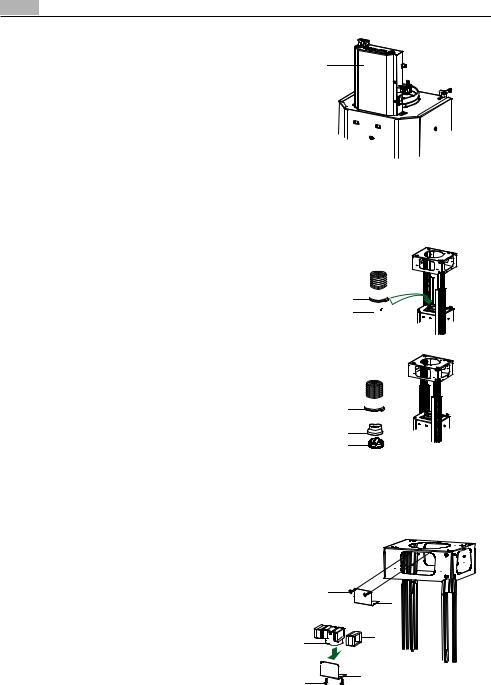
CONNESSIONE GRUPPO DI CONTROLLO
•Togliere le 2 Viti frontali vicino l’uscita dell’aria e usarle per avvitare il Gruppo di Controllo 50.
•Collegare tutti i connettori a quelli predisposti sul
Gruppo Scheda di Controllo verificando la loro compatibilità.
CONNESSIONI IN VERSIONE ASPIRANTE
Per installazione in Versione Aspirante collegare la Cappa alla tubazione di uscita per mezzo di un tubo rigido o flessibile di ø150 o 120 mm, la cui scelta è lasciata all‘installatore.
Collegamento tubo ø 150
•Inserire la Flangia ø 150 10 sull’Uscita del Corpo
Cappa.
•Fissare il tubo con adeguate fascette stringitubo. Il materiale occorrente non è in dotazione.
Collegamento tubo ø 120
•Per collegamento con tubo ø120 mm, inserire la
Flangia di riduzione 9 sulla flangia ø 150 10 precedentemente installata.
•Fissare il tubo con adeguate fascette stringitubo. Il materiale occorrente non è in dotazione.
•In ambedue i casi, togliere eventuali Filtri Antiodore al Carbone attivo.
CONNESSIONI IN VERSIONE FILTRANTE
•Inserire lateralmente le Prolunghe Raccordo 14.1 sul Raccordo 15.
•Inserire il Raccordo 15 nella Staffa di Sostegno 7.3 fissandolo con le Viti.
•Fissare la Staffa di Sostegno 7.3 fissandola con le Viti alla parte superiore.
•Assicurarsi che l’uscita delle Prolunghe Raccordo
14.1 risulti in corrispondenza delle bocchette del Camino sia in orizzontale che in verticale.
•Collegare il Raccordo 15 all’Uscita del Corpo Cappa per mezzo di un tubo rigido o flessibile di ø150 mm, la cui scelta è lasciata all'installatore.
•Assicurarsi della presenza del Filtro Antiodore al Carbone attivo.


��
IT - INSTALLAZIONE 9
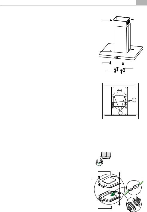
MONTAGGIO CAMINO E FISSAGGIO CORPO CAPPA
•Posizionare il Camino superiore e fissare nella parte superiore al Traliccio con 2 Viti 12c (2,9 x 6,5) in dotazione.
•Analogamente posizionare il Camino inferiore e fissare nella parte inferiore al Traliccio con 2 Viti 12c (2,9 x 6,5) in dotazione.
Prima di fissare il Corpo Cappa al Traliccio:
•Avvitare per metà le 2 Viti 12f sulla parte inferiore del traliccio in posizione laterale in corrispondenza dei 2 fori predisposti.
•Togliere i Filtri antigrasso dal Corpo Cappa;
•Togliere eventuali Filtri Antiodore al Carbone attivo.
•Sollevare il Corpo Cappa e incastrare le Viti 12f sulle asole (rif.A) fino a battuta.
•Fissare da sotto con 4 Viti 12q e 4 Rondelle 22 in dotazione il Corpo Cappa al Traliccio predisposto (rif.B) e serrare definitivamente tutte le Viti.
|
|
CONNESSIONE ELETTRICA
•Collegare la Cappa all’Alimentazione di Rete interponendo un Interruttore bipolare con apertura dei contatti di almeno 3 mm.
• Rimuovere i Filtri antigrasso (vedi par. “Manutenzione”) e assicurarsi che il connettore del Cavo di alimentazione sia correttamente inserito nella presa
dell’Aspiratore |
|
|
|
• Collegare il Connettore dei Comandi Cmd. |
|
|
|
• Collegare il Connettore dei Faretti Lux. |
|
||
|
|
||
• Riporre entrambi i Connettori nella Scatola di pro- |
|
|
|
tezione 24 chiudendola con 2 Viti 12e(2,9 x 9,5) in |
|
|
|
dotazione. |
|
|
|
• Fissare la Scatola di protezione al Corpo Cappa con 2 |
|
||
|
|
||
Viti 12c (2,9 x 6,5) in dotazione. |
|
|
|
• Per la Versione Filtrante montare il Filtro Antiodore al |
|
|
|
Carbone attivo. |
|
||
|
• Rimontare i Filtri Antigrasso.
10 IT - USO
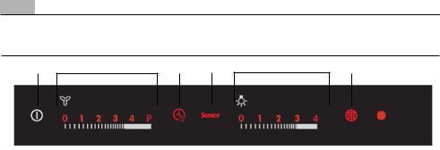
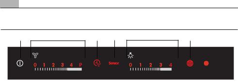
USO
A B C D E F
Tasto |
Funzione |
Specifiche |
|
|
|
A |
On/Off Funzioni Cappa |
Toccando il tasto a Cappa spenta si illuminano (intensità 50%) e vengono abilitate tutte |
|
|
le funzioni. |
|
|
Toccando il tasto a Cappa funzionante spegne disabilitando tutte le funzioni (Motore |
|
|
Off + Luci Off). |
B |
Gestisce Velocità |
Toccando l’area si attiva il motore alla velocità desiderata. |
|
motore: |
P = Velocità Intensiva, temporizzata a 5 minuti, al termine del tempo il sistema ritorna |
|
0-V1-V2-V3-V4-P |
alla precedente velocità, se attivata da Motore Off passa a V1. |
|
|
Al tocco della velocità desiderata, questa si illuminerà maggiormente (intensità 100%) |
|
|
rispetto alle altre funzioni (intensità 50%). |
|
|
|
C |
Funzione Delay |
Toccando il tasto si attiva lo spegnimento automatico ritardato del Motore e dell’Im- |
|
|
pianto di Illuminazione di 10 minuti. Attivabile solo da motore acceso, velocità non |
|
|
Intensiva e Sensor = Off. |
|
Attiva / Disattiva il |
Toccando il Tasto per 4 secondi (Motore Off + Luci Off), in assenza di altri allarmi, il |
|
ricevitore del Teleco- |
Led lampeggia per: |
|
mando. |
4 secondi indicando l’Attivazione del Telecomando |
|
|
2 secondi indicando la Disattivazione del Telecomando |
D |
Sensor |
In questa modalità la Cappa funziona in modo automatico per un massimo di 5 ore, al |
|
|
termine la funzione spegne il motore. |
|
|
La cappa modifica la velocità del motore in base a quanto percepito dal Sensore. |
|
|
I Tasti B e C non funzionano, si disattiva premendo il tasto o spegnendo la Cappa. |
|
|
|
E |
Gestisce Intensità Luce: |
Toccando l’area si accendono le Luci all’Intensità desiderata.Al tocco dell’Intensità |
|
0-L1-L2-L3-LMax |
Luce desiderata, questa si illuminerà maggiormente (intensità 100%) rispetto alle altre |
|
|
funzioni (intensità 50%). |
|
|
|
F |
Reset FiltriEffettua |
Dopo 100 ore di Funzionamento il Led è Acceso Fisso per segnalare la saturazione dei |
|
il Reset dell’allarme |
Filtri Metallici. |
|
saturazione Filtri Toc- |
Dopo 200 ore di Funzionamento il Led Lampeggia per segnalare la saturazione dei Filtri |
|
cando il tasto a Motore |
al Carbone Attivo. |
|
Spento. |
|
|
Attiva / Disattiva allar- |
Toccando il Tasto per 4 secondi (Motore Off + Luci Off), in assenza di altri allarmi, il |
|
me saturazione Filtri al |
Led lampeggia per: |
|
Carbone Attivo. |
4 secondi indicando l’Attivazione Allarmi Filtri al Carbone |
|
|
2 secondi indicando la Disattivazione Allarmi Filtri al Carbone |
Dopo aver collegato la cappa alla rete elettrica, i comandi saranno abilitati dopo circa 4 secondi. In tale periodo lampeggia il led "0" del tasto motore. A Cappa spenta nessuna funzione è visualizzata, è visibile solo la parte in chiaro del pannello comandi. Tutto il resto s’illuminerà (intensità 50%) toccando il Tasto A.
I Comandi s’attivano col tocco della funzione scelta che s’illuminerà maggiormente (intensità 100%) rispetto alle altre funzioni della Cappa (intensità 50%). Dopo 10 secondi di assenza comandi, rimarranno accese solo le funzioni selezionate (Intensità 100%) spegnendo tutto il resto(Intensità 50%). Dopo 7 ore di uso in assenza di comandi la Cappa si spegne (Motore Off + Luci Off), da questa situazione con un tocco si riabilitano le funzioni, al successivo è possibile selezionare la funzione desiderata.
È possibile attivare una funzione della Cappa(Velocità e Luce), non solo toccando il quadro comandi ma anche appoggiandoci il dito e scorrendo verso la funzione scelta senza alzarlo.
Se viene comandato lo spegnimento di motore e luci , portandoli a zero, rimangono accesi al 50% tutti i led dei comandi e se non ci sono altri comandi nei successivi 10sec , tutti led verranno spenti ad eccezione dei led “0”, che rimarranno on per altri 15minuti.
IT - OPZIONI CAPPA MODALITÀ SENSOR/ILLUMINAZIONE 11
OPZIONI CAPPA MODALITÀ SENSOR
Nel funzionamento in modalità Sensor influisce il tipo di piano utilizzato, sono state previste due possibilità:
• Piano elettrico;
• Piano a gas;
Inizialmente è selezionato il piano elettrico, per cambiare è necessario seguire la seguente procedura:
•Spegnere la cappa con il tasto on/off cappa
•Tenere premuto il tasto Sensor per 8 secondi fino al lampeggio del led:
•4 lampeggi indicano la selezione del piano elettrico;
•2 lampeggi per il piano a gas;
•Togliere l’alimentazione per 10 secondi e poi ricollegarla.
Ogni volta che viene cambiato il tipo di piano, viene eseguita la procedura di calibrazione.
Procedura di calibrazione: ogni volta che la cappa viene alimentata o viene cambiato il piano cottura si attiva la procedura di calibrazione del sensore, durante la quale la cappa non deve essere esposta a processi di cottura o investita da odori particolarmente intensi, tipo solventi o detergenti.
Tale processo prevede un tempo di:
•13min se è selezionato il piano elettrico;
•1 min se è selezionato il piano a gas;
Questa fase è segnalata dal lampeggio del led del tasto sensor se è stato premuto.Durante la calibrazione non accendere il motore.
Attenzione: non spruzzare direttamente sulla griglia i prodotti di pulizia ma di pulirla unicamente con panni imbevuti di detergen-
te. Evitare per la pulizia della griglia prodotti alcolici o siliconici.
Illuminazione
Attenzione: Questo apparecchio è provvisto di una luce LED bianca di classe 1M secondo la norma EN 60825-1: 1994 + A1:2002 + A2:2001; massima potenza ottica emessa@439nm: 7µW. Non osservare direttamente con strumenti ottici
(binocolo, lente d’ingrandimento….).
•Per la sostituzione contattare l’Assistenza
Tecnica. ("Per l'acquisto rivolgersi all'assistenza tecnica").
FOR PERFECT RESULTS
Thank you for choosing this AEG product. We have created it to give you impeccable performance for many years, with innovative technologies that help make life simpler – features you might not find on ordinary appliances. Please spend a few minutes reading to get the very best from it.
ACCESSORIES AND CONSUMABLES
In the AEG webshop, you’ll find everything you need to keep all your AEG appliances looking spotless and working perfectly. Along with a wide range of accessories designed and built to the high quality standards you would expect, from specialist cookware to cutlery baskets, from bottle holders to delicate laundry bags…
Visit the webshop at:
www.aeg-electrolux.com/shop
13 EN - RECOMMENDATIONS AND SUGGESTIONS/CHARACTERISTICS
EN - RECOMMENDATIONS AND SUGGESTIONS - The Instructions for Use apply to several versions of this appliance. Accordingly, you may find descriptions of individual features that do not apply to your specific appliance. The manufacturer will not be held liable for any damages resulting from incorrect or improper installation. The minimum safety distance between the cooker top and the extractor hood is 650 mm. Check that the mains voltage corresponds to that indicated on the rating plate fixed to the inside of the hood. For Class I appliances, check that the domestic power supply guarantees adequate earthing. Connect the extractor to the exhaust flue through a pipe of minimum diameter 120 mm.The route of the flue must be as short as possible. Do not connect the extractor hood to exhaust ducts carrying combustion fumes (boilers, fireplaces, etc.). If the extractor is used in conjunction with non electrical appliances (e.g. gas burning appliances), a sufficient degree of aeration must be guaranteed in the room in order to prevent the backflow of exhaust gas. The kitchen must have an opening communicating directly with the open air in order to guarantee the entry of clean air. The extractor hood has been designed exclusively for domestic use to eliminate kitchen smells. Never use the hood for purposes other than for which it has been designed. Never leave high naked flames under the hood when it is in operation. Adjust the flame intensity to direct it onto the bottom of the pan only, making sure that it does not engulf the sides. Deep fat fryers must be continuously monitored during use: overheated oil can burst into flames. Do not flambè under the range hood; risk of fire This appliance is not intended for use by persons (including children) with reduced physical, sensory or mental capabilities, or lack of experience and knowledge, unless they have been given supervision or instruction concerning use of the appliance by a person responsible for their safety. Children should be supervised to ensure that they do not play with the appliance. Switch off or unplug the appliance from the mainssupplybeforecarryingoutanymaintenancework.Cleanand/orreplacetheFiltersafterthespecifiedtimeperiod(Firehazard),Greasefilters Z Thefiltersmust be cleaned every 2 months of operation, or more frequently for particularly heavy usage, and can be washed in a dishwasher. - Activated charcoal filter W These filtersarenotwashableandcannotberegenerated,andmustbereplacedapproximatelyevery4monthsofoperation,ormorefrequentlywithheavyusage.Cleanthe hood using a damp cloth and a neutral liquid detergent. The symbol  ontheproductoronitspackagingindicatesthatthisproductmaynotbetreatedashousehold waste. Instead it shall be handed over to the applicable collection point for the recycling of electrical and electronic equipment. By ensuring this product is disposed of correctly, you will help prevent potential negative consequences for the environment and human health, which could otherwise be caused by inappropriate waste handling of this product. For more detailed information about recycling of this product, please contact your local city office, your household waste disposal service or
the shop where you purchased the product.
Connect the hood to the mains through a two-pole switch having a contact gap of at least 3 mm. Warning: Before installing the Hood, remove the protective films (white and transparent).
CHARACTERISTICS
Dimensions

EN - RECOMMENDATIONS AND SUGGESTIONS/CHARACTERISTICS 14
Components
Ref.Q.ty Product Components
11 Hood Canopy complete with: Controls, Lights, Filters
21 Telescopic chimney made up of:
2.11 Upper chimney
2.21 Lower chimney
7.11 Telescopic frame complete with Suction fan, made up of:
7.1a1 Upper frame
7.1b1 Lower frame
91 Reduction flange ø 150-120 mm
101 Damper ø 150
14.12 |
Air Outlet Connection Extension |
|
15 |
1 |
Air Outlet Connection |
24 |
1 |
Connection box |
25 |
|
Hose clamps (not included) |
50 |
1 |
Control Board Group |
|
|
|
Ref.Q.ty |
Installation Components |
|
7.3 |
1 |
Air Outlet Connection Support |
11 |
4 |
Wall Plugs ø 10 |
12c 8 |
Screws 2,9 x 6,5 |
|
12e 4 |
Screws 2,9 x 9,5 |
|
12f 2 |
Screws M4 x 80 |
|
12g 4 |
Screws M6 x 80 |
|
12h 4 |
Screws 5,2 x 70 |
|
12q 4 |
Screws 3,5 x 9,5 |
|
21 |
1 |
Drilling template |
228 6.4 mm int. dia washers
234 M6 nuts
Q.ty Documentation
1 Instruction Manual
|
|
|
|
|
|
|
|
|
|
|
|
|
||
|
|
|
|
|
|
|
|
|
|
|
|
|
|
|
|
|
|
|
|
|
|
|
|
|
|
|
|
|
|
|
|
|
|
|
|
|
|
|
|
|
|
|
||
|
|
|
|
|
|
|
|
|
|


15 EN - INSTALLATION
INSTALLAtION
Drilling the Ceiling/shelf and fixing the frame
•Use a plumb line to mark the centre of the hob on the ceiling/support shelf.
•Place the drilling template 21 provided on the ceiling/support shelf, making sure that the template is in the correct position by lining up the axes of the template with those of the hob.
•Mark the centres of the holes in the template.
•Drill the holes at the points marked:
•For concrete ceilings, drill for plugs appropriate to the screw size.
•For hollow brick ceilings with wall thickness of 20 mm: drill ø 10 mm(immediately insert the
Dowels 11 supplied).
•For wooden beam ceilings, drill according to the wood screws used.
•For wooden shelf, drill ø 7 mm.
•For the power supply cable feed, drill ø 10 mm.
•For the air outlet (Ducted Version), drill according to the diameter of the external air exhaust duct connection.
•Insert two screws of the following type, crossing them and leaving 4-5 mm from the ceiling:
•For concrete ceilings, use the appropriate plugs for the screw size (not provided).
•for Cavity ceiling with inner space, with wall thickness of approx. 20 mm, Screws 12h, supplied.
•For wooden beam ceilings, use 4 wood screws (not provided).
•For wooden shelf, use 4 screws 12g with washers 22 and nuts 23, provided.

EN - INSTALLATION 16
FIXING THE FRAME
•Loosen the two screws fastening the lower chimney and remove this from the lower frame.
•Loosen the two screws fastening the upper chimney and remove this from the upper frame.
If you wish to adjust the height of the frame, proceed as follows:
•Unfasten the metric screws joining the two columns, located at the sides of the frame.
• Adjust the frame to the height required, then replace all the screws removed as above.
• Insert the upper chimney stack from above, and leave it running free on the frame.
• Lift up the frame, fit the frame slots onto the screws up to the slot end positions.
•Tighten the two screws and fasten the other two screws provi-ded with the hood.
Before tightening the screws completely it is possible |
|
|
to adjust the frame by turning it. Make sure that the |
|
|
screws do not come out of their seats in the slotted |
|
|
holes. |
|
|
•The frame mountings must be secure to withstand the weight of the hood and any stresses caused by the occasional side thrust applied to the device.
On completion, check that the base is stable, even |
|
|
if the frame is subjected to bending. |
|
|
•In all cases where the ceiling is not strong enough at the suspension point, the installer must provide strengthening using suitable plates and backing pieces anchored to the structurally sound parts.
17 EN - INSTALLATION
CONNECTION CONTROL GROUP
•Unscrew the screws near the Air outlet and use these for attaching the Control Group 50.
•Connect up all the connectors to the sockets provided on the Control Board Unit, making sure they are compatible.
CONNECTION IN DUCTING VERSION
When installing the ducting version, connect the hood to the chimney using either a flexible or rigid pipe ø 150 or 120 mm, the choice of which is left to the installer.
To install a ø 150
•To install the dumper 10.
•Fix the pipe in position using sufficient pipe clamps
(not supplied).
To install a ø 120
•To install a ø 120 mm air exhaust connection, insert the reducer flange 9 on the dumper 10.
•Fix the pipe in position using sufficient pipe clamps
(not supplied).
•Remove any activated charcoal filters.


��
CONNECTION IN RECYCLING VERSION
•Insert the Connector extensions 14.1 into the side of the Connector 15.
•Insert the Connector 15 into the Support bracket 7.3 and fix it with the screws.
•Fasten the Support bracket 7.3, fixing it to the upper part with the Screws.
•Make sure that the Connector extensions outlet 14.1 is in correspondence with the Chimney openings both horizontally and vertically.
•Join the Connector 15 to the Hood canopy outlet us-ing a rigid or flexible pipe ø¸150 mm, selection of which is at the discretion of the installation technician.
•Make sure that the Activated charcoal odour filter has been fitted.

EN - INSTALLATION 18
FLUE ASSEMBLY - MOUNTING THE HOOD BODY
•Position the upper chimney section and fix the upper part to the frame using the 2 screws 12c (2,9 x 6,5) provided.
•Similarly, position the lower chimney section and fix the lower part to the frame using the 2 screws 12c (2,9 x 6,5) provided.
Before fixing the hood body to the frame:
•Screw the 2 screws 12f half way into the holes provided in the sides of the bottom of the frame.
•Remove the grease filters from the hood canopy.
•Remove any activated charcoal filters.
•Lift the hood canopy and engage the screws 12f in the slots (A) as far as they will go.
•Working from below, fix the hood canopy to the frame (B), using the 4 screws 12q and 4 washers 22 provided, then tighten all the screws securely.
ELECTRICAL CONNECTION
•Connect the hood to the mains through a twopole switch ha-ving a contact gap of at least 3 mm.
•Remove the grease filters (see paragraph Maintenance) being sure that the connector of the feeding cable is correctly inserted in the socket placed on the side of the fan.
•Connect the control connector Cmd.
•Connect the lights connector Lux.
•Place the connectors in the junction box 24 and close it using the 2 screws 12e (2,9 x 9,5) provided.
•Fix the junction box to the hood body using the 2 screws 12c (2,9 x 6,5) provided.
•For the recirculation version, fit the activated carbon odour fil-ter.
•Replace the grease filters.
|
|
|
|
19 EN - USE
USE
A B C D E F
Button |
Function |
Specifications |
|
|
|
A |
Hood Functions On/Off |
When the button is touched with the hood turned off, all functions light up |
|
|
(intensity 50%) and are enabled. |
|
|
When the button is touched with the hood in operation, all functions are turned |
|
|
off and disabled (Motor Off + Lights Off). |
B |
Manages motor speed: |
When the area is touched, the motor starts at the speed required. |
|
0-V1-V2-V3-V4-P |
P = Intensive Speed, timed for 5 minutes, after which the system returns to the |
|
|
previous speed. |
|
|
When activated from Motor Off it returns to speed V1.When the required speed |
|
|
is touched, it will become brighter (intensity 100%) than the other functions |
|
|
(intensity 50%). |
|
|
|
C |
Delay function |
Touching this button activates automatic shutdown of the Motor, the Fans and |
|
|
the Lighting with a 10 minute delay. It can only be activated with the motor on, |
|
|
running at any speed except Intensive, and with the Sensor = Off. |
|
Enables / Disables the |
When this button is pressed and held for 4 seconds (Motor Off + Lights Off, in |
|
Remote Control Receiver. |
the absence of other alarms, the Led will light up for: |
|
|
4 seconds to indicate that the Remote Control has been Activated |
|
|
2 seconds to indicate that the Remote Control has been Deactivated |
D |
Sensor |
In this mode the Hood operates automatically for a maximum of 5 hours, after |
|
|
which it switches the Motor off. |
|
|
The hood modifies the speed of the motor according to the findings of the sensor. |
|
|
Buttons B and C do not work. The function is disabled by pressing the Button or |
|
|
turning the hood off. |
|
|
|
E |
Manages Lighting Inten- |
When this area is touched, the Lights turn on at the required intensity. |
|
sity: 0-L1-L2-L3-LMax |
When the lighting intensity is touched, it will become brighter (intensity 100%) |
|
|
than the other functions (intensity 50%). |
|
|
|
F |
Filter ResetResets the |
After 100 hours operation the Led lights up continuously to indicate saturation of |
|
Filter Saturation alarm |
the Metal Grease Filters. |
|
when the button is tou- |
After 200 hours operation the Led flashes to indicate saturation of the Activated |
|
ched with the motor and |
Charcoal Filters. |
|
lighting turned off. |
|
|
Enables/Disables the |
When this button is pressed and held for 4 seconds(Motor Off + Lights Off), in the |
|
Activated Charcoal Filter |
absence of other alarms, the Led will light up for: |
|
Alarm. |
4 seconds to indicate the Activated Charcoal Filter Alarm has been activated |
|
|
2 seconds to indicate the Activated Charcoal Filter Alarm has been deactivated |
|
|
|
After connecting the hood to the mains, the commands are activated after 4seconds. When the Hood is switched off, none of the functions is displayed, and only the normal lettering on the control panel is visible. All the rest will light up (intensity 50%) when button A is touched.
The controls are activated by touching the selected function, which will light up more brightly (intensity 100%) with respect to the other hood functions (intensity 50%). When no commands are given for at least 10 seconds, only the selected functions will be lighted (Intensity 100%) and all the rest will turn off (Intensity 50%). After 7 hours in operation, if no further commands are given the hood will switch off (Motor Off + Lights Off), from here you can touch for activated the function, and the next touch you can select the desired function.It is possible to activate one of the hood functions (Speed and Lighting) not just by touching the control panel, but also by placing a finger on the panel and sliding it towards the chosen function without lifting it off. If the motor and lights are turned off, by setting them to zero, all the command LEDs will remain on at 50%, and if no further commands are given in the next 10 seconds, then all the LEDs will be turned off with the exception of the “0” LEDs, which will remain on for a further 15 minutes.
EN - HOOD OPTIONS IN SENSOR MODE/LIGHTING 20
HOOD OPTIONS IN SENSOR MODE
When operating in Sensor mode, the type of hob being used has an influence. Two options are available:
• Electric hob;
• Gas hob;
Initially it is set to electric hob. To change the setting, proceed as follows:
•Turn the hood off using the hood on/ off button
•Press and hold the Sensor button for 8 seconds until the LED flashes as described:
•4 flashes indicate selection of the electric hob;
•2 flashes indicate selection of the gas hob;
•Remove power for 10 seconds and then reconnect it.
The calibration procedure is carried out every time the type of hob is changed.
Calibration procedure: every time the hood is turned on or the type of hob is changed, the sensor calibration procedure is run. During this time the hood must not be used for cooking or subjected to particularly intense smells, for example solvents or detergents.
This process requires:
•13 minutes if the electric hob has been selected;
•1 minute if the gas hob has been selec-
ted;
This phase is marked by flashing of the LED on the sensor button, if it has been pressed.Do not turn the motor on during calibration.
Warning: Do not spray directly on the grill cleaning products but only clean with a cloth soaked in detergent. Avoid cleaning the grill alcohol or silicone products.
LIGHTING
Warning: This appliance is fitted with a white LED lamp classed as 1M according to EN 60825-1: 1994 + A1:2002 + A2:2001 standards; maximum optical power emitted @439nm: 7µW. Do not look directly at the light through optical devices (binoculars, magnifying glasses…).
•For replacement contact technical support.
("To purchase contact technical support")
POUR DES RÉSULTATS PARFAITS
Merci d'avoir choisi ce produit AEG. Nous l'avons créé pour vous offrir la meilleure performance pour une longue durée, avec des technologies innovantes qui vous simplifient la vie - autant de caractéristiques que vous ne trouverez pas sûrement pas sur d'autres appareils. Veuillez prendre quelques instants pour lire cette notice afin d'utiliser au mieux votre appareil.
ACCESSOIRES ET CONSOMMABLES
Dans la boutique en ligne d'AEG, vous trouverez tout ce qu'il vous faut pour que vos appareils AEG fonctionnent parfaitement. Sans oublier une vaste gamme d'accessoires conçus et fabriqués selon les critères de qualité les plus élevés qui soient, des articles de cuisine spécialisés aux range-couverts, des porte-bouteilles aux sacs à linge délicats...
Visit the webshop at:
www.aeg-electrolux.com/shop

22 FR - CONSEILS ET SUGGESTION/CARACTERISTIQUES
FR - CONSEILS ET SUGGESTIONS - La présente notice d’emploi vaut pour plusieurs versions de l’appareil. Elle peut contenir des descriptions d’accessoires ne figurant pas dans votre appareil. Le fabricant décline toute responsabilité en cas de dommage dû à une installation non correcte ou non conforme aux règles de l’art. La distance minimale de sécurité entre le plan de cuisson et la hotte doit être de 650 mm au moins. Vérifier que la tension du secteur correspond à la valeur qui figure sur la plaquette apposée à l’intérieur de la hotte. Pour lesAppareils appartenant à la Ière Classe, veiller à ce que la mise à la terre de l’installation électrique domestique ait été effectuée conformément aux normes en vigueur. Connecter la hotte à la sortie d’air aspiré à l’aide d’une tuyauterie d’un diamètre égal ou supérieur à 120 mm. Le parcours de la tuyauterie doit être le plus court possible. Ne pas connecter la hotte à des conduites d’évacuation de fumées issues d’une combustion tel que (Chaudière, cheminée, etc…). Si vous utilisez des appareils qui ne fonctionnent pas à l’électricité dans la pièce ou est installée la hotte
(par exemple: des appareils fonctionnant au gaz), vous devez prévoir une aération suffisante du milieu. Si la cuisine en est dépourvue, pratiquez une ouverture qui communique avec l’extérieur pour garantir l’infiltration de l’air pur. La hotte a été conçue exclusivement pour l’usage domestique, dans le but d’éliminer les odeurs de la cuisine. Ne jamais utiliser abusivement la hotte. Ne pas laisser les flammes libres à forte intensité quand la hotte est en service. Toujours régler les flammes de manière à éviter toute sortie latérale de ces dernières par rapport au fond des marmites. Contrôler les friteuses lors de l’utilisation car l’huile surchauffée pourrait s’enflammer. Ne pas préparer d’aliments flambés sous la hotte de cuisine : risque d’incendie Cet appareil ne doit pas être utilisé par des personnes (y compris les enfants) ayant des capacités psychiques, sensorielles ou mentales réduites, ni par des personnes n’ayant pas l’expérience et la connaissance de ce type d’appareils, à moins d’être sous le contrôle et la formation de personnes responsables de leur sécurité. Les enfants doivent être surveillés pour s’assurer qu’ils ne jouent pas avec l’appareil. Avant de procéder à toute opération d’entretien, retirer la hotte en retirant la fiche ou en actionnant l’interrupteur général. Effectuer un entretien scrupuleux et en temps dû des Filtres, à la cadence conseillée (Risque d’incendie), Filtres anti-graisse Z Lavables au lave-vaisselle, ils doivent être lavés environ tous les 2 mois d’emploi ou plus fréquemment en cas d’emploi particulièrement intense. - Filtre anti-odeur W Il ne sont pas lavables ni régénérables, il faut les remplacer au moins tous les 4 mois d’emploi ou plus fréquemment en cas d’emploi particulièrement intense. Pour le nettoyage des surfaces de la hotte, il suffit d’utiliser un chiffon humide et détersif liquide neutre. Le symbole  sur le produit ou son emballage indique que ce produit ne peut être traité comme déchet ménager. Il doit plutôt être remis au point de ramassage concerné, se chargeant du recyclage du matériel électrique et électronique. En vous assurant que ce produit est éliminé correctement, vous favorisez la prévention des conséquences négatives pour l’environnement et la santé humaine qui, sinon, seraient le résultat d’un traitement inapproprié des déchets de ce produit. Pour obtenir plus de détails sur le recyclage de ce produit, veuillez prendre contact avec le bureau
muni-cipal de votre région, votre service d’élimination des déchets ménagers ou le magasin où vous avez acheté le produit. Brancher la hotte sur le secteur en interposant un interrupteur bipolaire avec ouverture des contacts d’au moins 3 mm.
Attention : Retirez les films de protection (blanc et transparent) avant d’installer la hotte.
CARACTERISTIQUES
Encombrement
FR - CONSEILS ET SUGGESTION/CARACTERISTIQUES 23
Composants
Réf.Q.té Composants de Produit
11 Corps Hotte équipé de: Comandes, Lumière, Filtres
21 Cheminée Télescopique formée de :
2.1 1 Cheminée Supérieure
2.2 1 Cheminée Inférieure
7.1 1 Treillis télescopique avec Aspirateur, formé par:
7.1a 1 Treillis supérieur
7.1b 1 Treillis inférieur
91 Flasque de Réduction ø 150-120 mm
101 Flasque ø 150-120 mm
14.1 2 Rallonge Raccord Sortie Air
15 1 Raccord Sortie Air
24 1 Boîte connexions
25Colliers de serrage serre-tube (non compris)
50 |
1 |
Carte de Contrôle des Groupes |
|
|
|
Réf.Q.té |
Composants pour l’installation |
|
7.3 |
1 |
Bride Support Raccord |
11 |
4 |
Chevilles ø 10 |
12c 8 |
Vis 2,9 x 6,5 |
|
12e 4 |
Vis 2,9 x 9,5 |
|
12f 2 |
Vis M4 x 80 |
|
12g 4 |
Vis M6 x 80 |
|
12h 4 |
Vis 5,2 x 70 |
|
12q 4 |
Vis 3,5 x 9,5 |
|
21 |
1 |
Gabarit de perçage |
22 |
8 |
Rondelles øi 6,4 |
23 |
4 |
Écrous M6 |
|
|
|
|
Q.té |
Documentation |
|
1 |
Manuel d’instructions |
|
|
|
|
|
|
|
|
|
|
|
|
|
||
|
|
|
|
|
|
|
|
|
|
|
|
|
|
|
|
|
|
|
|
|
|
|
|
|
|
|
|
|
|
|
|
|
|
|
|
|
|
|
|
|
|
|
||
|
|
|
|
|
|
|
|
|
|


 Loading...