


HC8830EN
TOOLS AND
MATERIALS REQUIRED (continued)
PLAN DUCTWORK
INSTALLATION (continued)
For Ductfree Installations Only:
❏ One two-pack HF88 Replacement Filter Kit
For Installation On Kitchen Cabinets With Recessed Bottoms
Only:
❏ Two 1” x 2” x 12” (approximate length) wood strips (purchase
locally)
❏ Four 1-1/4” long flat head wood screws (purchase locally)
to fasten strips to cabinet bottom
PLAN DUCTWORK INSTALLATION
For Ducted Installations Only:
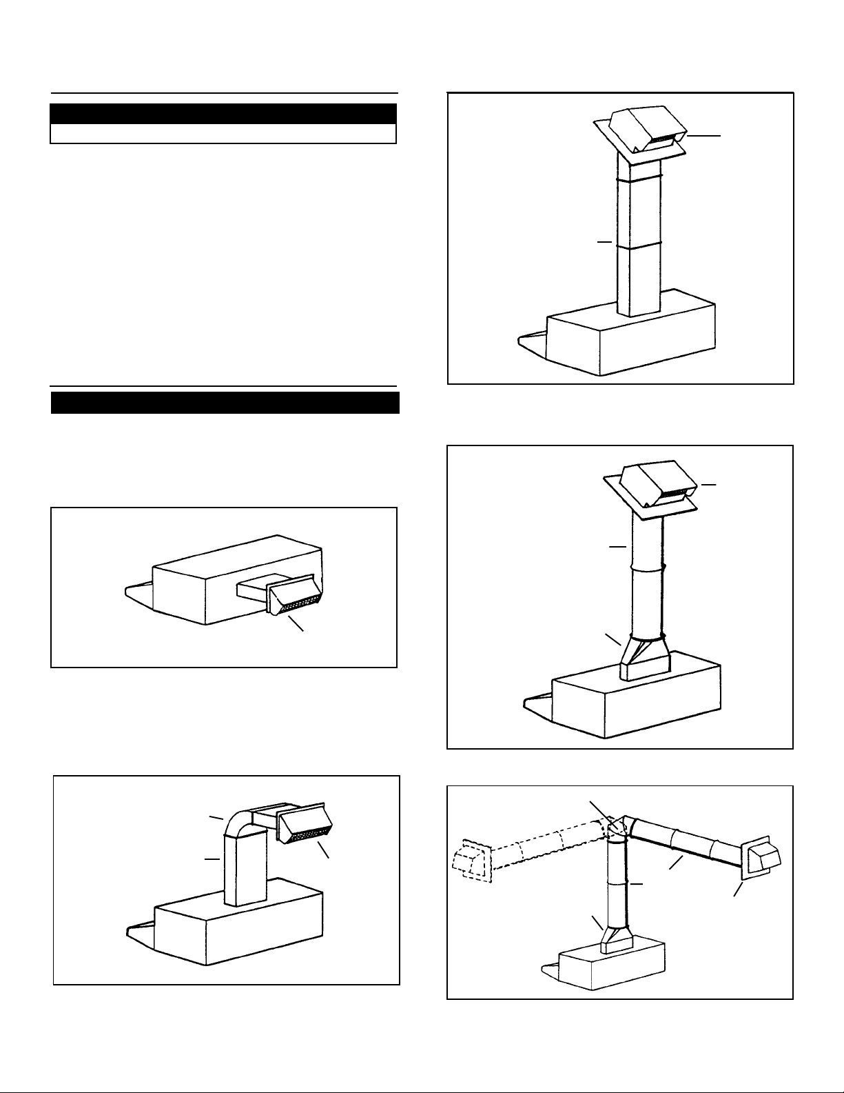
Begin planning ductwork by deciding where duct will run
between hood and outside. For best performance, use
shortest possible duct run and a minimum number of elbows.
In more complex situations, 3-1/4” x 10” duct can be
converted to round duct by means of a transition. FIGS 1A 1E show several choices.
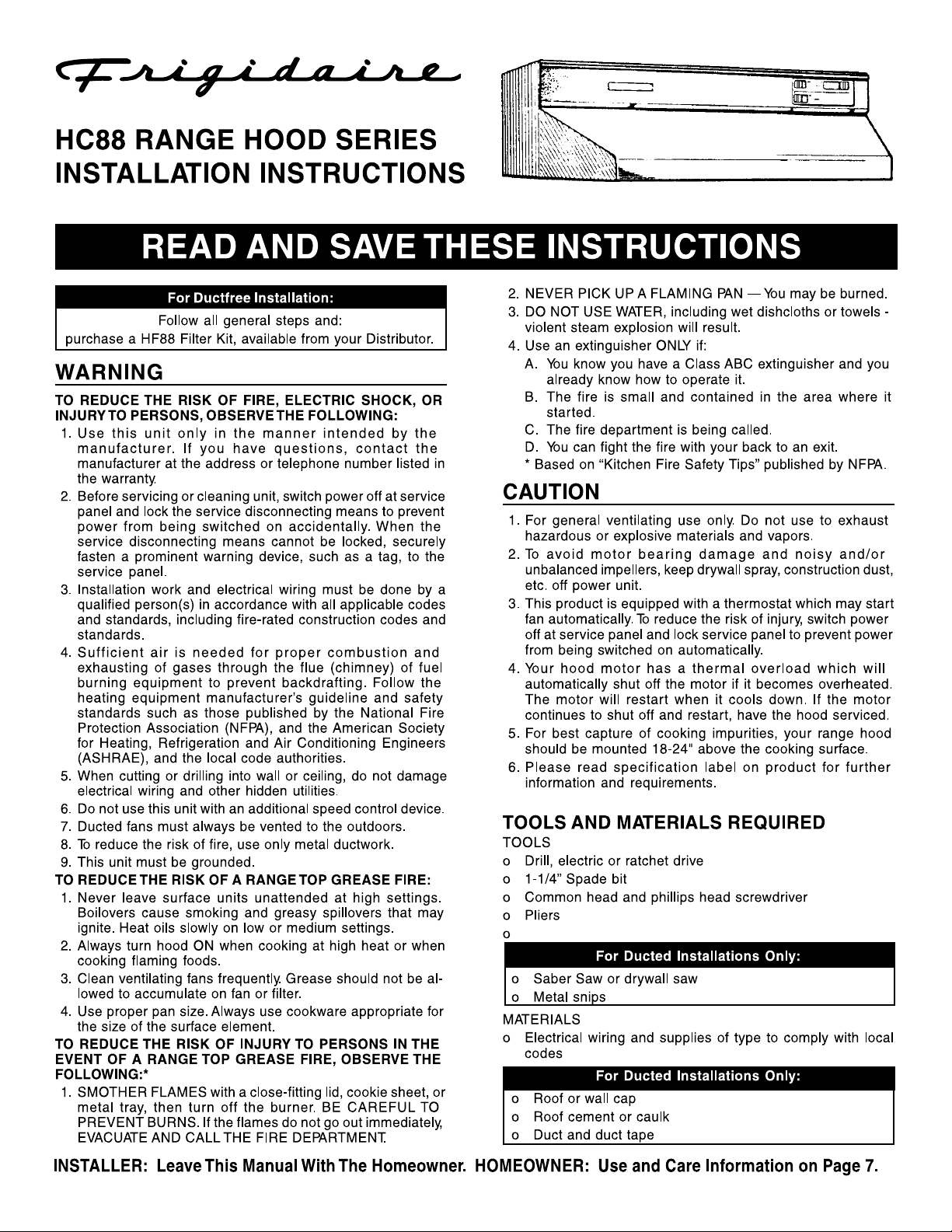
FIG. 1C
ROOF CAP
3-1/4" X 10" DUCT
FIG. 1C: Ducting straight up through roof using 3-1/4” x 10”
duct. For single story installations.
FIG. 1D
ROOF CAP
FIG. 1A
WALL CAP
FIG. 1A: Ducting directly through outside wall. If wall cap is
used directly off back of hood, check to make sure that
damper flap in damper/duct connector on hood does not
interfere with damper flap in wall cap. If it does, remove flap
on hood damper/duct connector.
FIG. 1B
ELBOW
3-1/4" X 10" DUCT
WALL
CAP
6" ROUND DUCT
3–1/4" X 10" TO 6"
ROUND DUCT
TRANSITION
FIG. 1D: Straight up through roof using round duct.
FIG. 1E
ADJUSTABLE ELBOW
3–1/4" X 10" TO 6"
ROUND DUCT
TRANSITION
6" ROUND
DUCT
WALL CAP
FIG. 1B: At times it will be easier to run duct vertically and
use an elbow.
FIG. 1E: Ducting between ceiling joists for multi-story
installations or through soffits above cabinets where soffit
2
connects to outside walls.
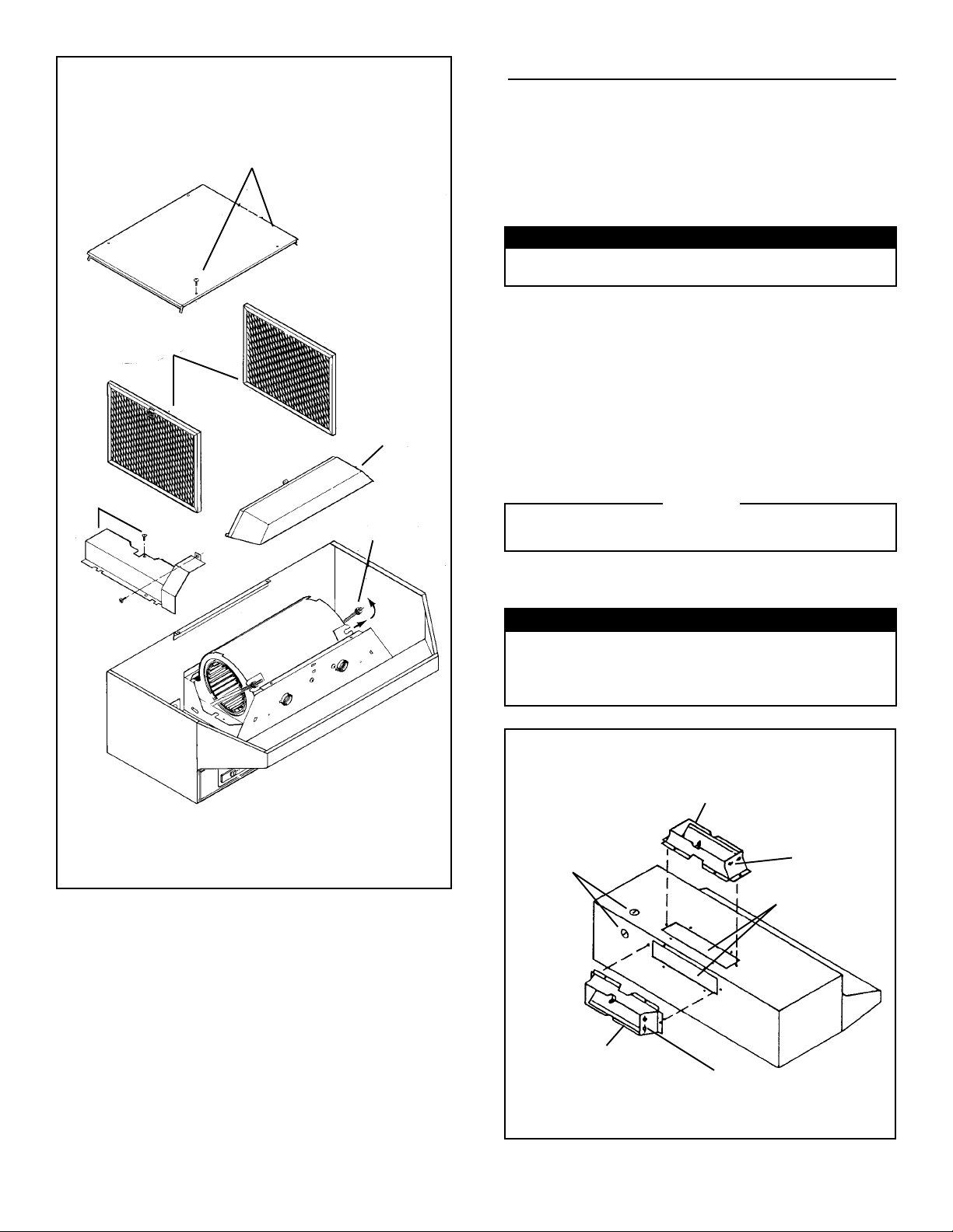
FIG. 2
STEP 4
STEP 3
STEP 2
STEP 6
STEP 5
PREPARE HOOD
1. Unpack hood and check contents. You should receive:
1 - assembled hood
1 - plastic bag, containing:
4 - 7/8” wood screws for mounting hood to cabinet
2 - 1/4” black sheet metal screws for mounting damper/
duct connector to hood
2 - aluminum filters
1 - damper/duct connector
For Ductfree Installations Only:
Discard damper/duct connector and two black sheet metal
screws.
For Steps 2 - 6 below, refer to FIG. 2.
2. Set hood upside down and remove bottom cover and
screws.
3. Remove filters.
4. Remove wiring box cover and screws.
5. To make hood lighter and easier to handle, remove blower
assembly.
a.) Unplug blower.
b.) Loosen knurled nuts on mounting rods and slip rods
out of blower mounting brackets. Do not remove nuts
completely from rods.
c.) Lift out blower and set blower aside.
CAUTION
DO NOT GRASP BLOWER BY BLOWER WHEELS.
WHEELS MAY BE DAMAGED.
6. Remove light lens. Squeeze sides of lens toward center of
hood and lift lens out.
7. Remove either top or rear electrical knockout. (FIG. 3)
For Ducted Installations Only:
7. Remove either top or rear duct knockout. (FIG. 3)
Fasten damper/duct connector to hood over opening.
Use two black sheet metal screws provided in parts bag.
(FIG. 3)
FIG. 3
VERTICAL DUCTING*
ELECTRICAL
KNOCKOUTS
HORIZONTAL DUCTING*
HINGE
PINS
* FOR DUCTED INSTALLATIONS ONLY.
3
HINGE
PINS
DUCT
KNOCKOUTS*
 Loading...