


QDFR Unit
Table of contents
 Loading...
)
)
(R
(G
M
N
R
E
O
TEST
T
M
)
)
(Y
(G
D
G
N
N
E
E
LBK
N
F
K
B
L
DS1 4
T
C
E
L
E
S
DS1 3
H
C
QDFR
1
DS1 2
DS1 1
7
L
OPTICS
7
30
1
8
1
®
Quad Fiber Remote (QDFR) Unit
Installation and Maintenance Practice
Document Number: 61181307L7-5E
CLEI: M3M1100B _ _
July 2006

Quad Fiber Remote (QDFR) Unit Installation and Maintenance Practice
Front Matter
Trademarks
Any brand names and product names included in this document are trademarks, registered
trademarks, or trade names of their respective holders.
To the Holder of the Document
The contents of this document are current as of the date of publication. ADTRAN® reserves the
right to change the contents without prior notice.
In no event will ADTRAN be liable for any special, incidental, or consequential damages or
for commercial losses even if ADTRAN has been advised thereof as a result of issue of this
document.
®
901 Explorer Boulevard
P.O. Box 140000
Huntsville, AL 35814-4000
(256) 963-8000
©2006 ADTRAN, Inc.
All Rights Reserved.
ii 61181307L7-5E

Revision History
Revision Date Description of Changes
A July 2005 Initial release
B December 2004 Added front panel LED information in Table 2.
C April 2005 Added QDFR Provisioning menu defaults in Table 3.
D June 2006 Changed connector designation from RJ-45 to RJ-48C.
Changed Transmit Level values to Output Optical Power
values in Table 5. Updated document format.
E July 2006 Updated CLEI.
Conventions
The following typographical conventions are used in this document:
This font indicates a cross-reference link. First-time references to tables and figures are
shown in this font.
This font indicates screen menus, fields, and parameters.
T
HIS FONT indicates keyboard keys (ENTER, ESC, ALT). Keys that are to be pressed simulta-
neously are shown with a plus sign (A
pressed at the same time).
LT+X indicates that the ALT key and X key should be
This font indicates references to other documentation and is also used for emphasis.
This font indicates on-screen messages and prompts.
This font indicates text to be typed exactly as shown.
This font indicates silkscreen labels or other system label items.
This font is used for strong emphasis.
NOTE
Notes inform the user of additional, but essential, information or
features.
CAUTION
Cautions inform the user of potential damage, malfunction, or disruption to equipment, software, or environment.
WARNING
Warnings inform the user of potential bodily pain, injury, or death.
61181307L7-5E iii

Quad Fiber Remote (QDFR) Unit Installation and Maintenance Practice
Training
ADTRAN offers training courses on our products. These courses include overviews on product
features and functions while covering applications of ADTRAN product lines. ADTRAN
provides a variety of training options, including customized training and courses taught at our
facilities or at customer sites.
For inquiries concerning training, contact ADTRAN:
Training Phone: 800-615-1176, ext. 7500
Training Fax: 256-963-6700
Training Email: training@adtran.com
iv 61181307L7-5E

Contents
General . . . . . . . . . . . . . . . . . . . . . . . . . . . . . . . . . . . . . . . . . . . . . . . . . . . . . . . . . . . . . . . . . . . . . . . . . . . . . . . . . . 1
Description . . . . . . . . . . . . . . . . . . . . . . . . . . . . . . . . . . . . . . . . . . . . . . . . . . . . . . . . . . . . . . . . . . . . . . . . . . . . 1
Features . . . . . . . . . . . . . . . . . . . . . . . . . . . . . . . . . . . . . . . . . . . . . . . . . . . . . . . . . . . . . . . . . . . . . . . . . . . . . . 2
Compliance . . . . . . . . . . . . . . . . . . . . . . . . . . . . . . . . . . . . . . . . . . . . . . . . . . . . . . . . . . . . . . . . . . . . . . . . . . . . 2
Installation . . . . . . . . . . . . . . . . . . . . . . . . . . . . . . . . . . . . . . . . . . . . . . . . . . . . . . . . . . . . . . . . . . . . . . . . . . . . . . . 3
Shipping Contents . . . . . . . . . . . . . . . . . . . . . . . . . . . . . . . . . . . . . . . . . . . . . . . . . . . . . . . . . . . . . . . . . . . . . . . . . 3
Installing the QDFR . . . . . . . . . . . . . . . . . . . . . . . . . . . . . . . . . . . . . . . . . . . . . . . . . . . . . . . . . . . . . . . . . . . . . 3
Front Panel LEDs . . . . . . . . . . . . . . . . . . . . . . . . . . . . . . . . . . . . . . . . . . . . . . . . . . . . . . . . . . . . . . . . . . . . . . . 3
Front Panel Pushbuttons . . . . . . . . . . . . . . . . . . . . . . . . . . . . . . . . . . . . . . . . . . . . . . . . . . . . . . . . . . . . . . . . . 4
Loop Connections . . . . . . . . . . . . . . . . . . . . . . . . . . . . . . . . . . . . . . . . . . . . . . . . . . . . . . . . . . . . . . . . . . . . . . . . . 5
Operation . . . . . . . . . . . . . . . . . . . . . . . . . . . . . . . . . . . . . . . . . . . . . . . . . . . . . . . . . . . . . . . . . . . . . . . . . . . . . . . . 5
Power Interface . . . . . . . . . . . . . . . . . . . . . . . . . . . . . . . . . . . . . . . . . . . . . . . . . . . . . . . . . . . . . . . . . . . . . . . . 5
Diagnostics . . . . . . . . . . . . . . . . . . . . . . . . . . . . . . . . . . . . . . . . . . . . . . . . . . . . . . . . . . . . . . . . . . . . . . . . . . . . 5
Provisioning . . . . . . . . . . . . . . . . . . . . . . . . . . . . . . . . . . . . . . . . . . . . . . . . . . . . . . . . . . . . . . . . . . . . . . . . . . . . . . 6
Menu Structure. . . . . . . . . . . . . . . . . . . . . . . . . . . . . . . . . . . . . . . . . . . . . . . . . . . . . . . . . . . . . . . . . . . . . . . . . . . . 7
Menu . . . . . . . . . . . . . . . . . . . . . . . . . . . . . . . . . . . . . . . . . . . . . . . . . . . . . . . . . . . . . . . . . . . . . . . . . . . . . . . . . 7
Screen . . . . . . . . . . . . . . . . . . . . . . . . . . . . . . . . . . . . . . . . . . . . . . . . . . . . . . . . . . . . . . . . . . . . . . . . . . . . . . . 7
Menu Navigation . . . . . . . . . . . . . . . . . . . . . . . . . . . . . . . . . . . . . . . . . . . . . . . . . . . . . . . . . . . . . . . . . . . . . . . . . . 7
Menu Descriptions. . . . . . . . . . . . . . . . . . . . . . . . . . . . . . . . . . . . . . . . . . . . . . . . . . . . . . . . . . . . . . . . . . . . . . . . . 8
QDF Unit Information Screen . . . . . . . . . . . . . . . . . . . . . . . . . . . . . . . . . . . . . . . . . . . . . . . . . . . . . . . . . . . 9
Provisioning Menu . . . . . . . . . . . . . . . . . . . . . . . . . . . . . . . . . . . . . . . . . . . . . . . . . . . . . . . . . . . . . . . . . . 10
Status Screen . . . . . . . . . . . . . . . . . . . . . . . . . . . . . . . . . . . . . . . . . . . . . . . . . . . . . . . . . . . . . . . . . . . . . . 11
Auto In Service Screen . . . . . . . . . . . . . . . . . . . . . . . . . . . . . . . . . . . . . . . . . . . . . . . . . . . . . . . . . . . . . . 11
Loopback and Test Commands Menu . . . . . . . . . . . . . . . . . . . . . . . . . . . . . . . . . . . . . . . . . . . . . . . . . . . 12
Loopback Control Menu . . . . . . . . . . . . . . . . . . . . . . . . . . . . . . . . . . . . . . . . . . . . . . . . . . . . . . . . . . 12
Test Jack Configuration Screen . . . . . . . . . . . . . . . . . . . . . . . . . . . . . . . . . . . . . . . . . . . . . . . . . . . . 13
BERT Test Screen . . . . . . . . . . . . . . . . . . . . . . . . . . . . . . . . . . . . . . . . . . . . . . . . . . . . . . . . . . . . . . . 14
Self-Tests Screen . . . . . . . . . . . . . . . . . . . . . . . . . . . . . . . . . . . . . . . . . . . . . . . . . . . . . . . . . . . . . . . 16
Performance History Menu . . . . . . . . . . . . . . . . . . . . . . . . . . . . . . . . . . . . . . . . . . . . . . . . . . . . . . . . . . . 16
Performance History Channel # Menu . . . . . . . . . . . . . . . . . . . . . . . . . . . . . . . . . . . . . . . . . . . . . . . 17
Performance History Fiber Menu . . . . . . . . . . . . . . . . . . . . . . . . . . . . . . . . . . . . . . . . . . . . . . . . . . . . 17
Scratch Pad, Circuit ID Menu . . . . . . . . . . . . . . . . . . . . . . . . . . . . . . . . . . . . . . . . . . . . . . . . . . . . . . . . . . 19
Alarm History Menu . . . . . . . . . . . . . . . . . . . . . . . . . . . . . . . . . . . . . . . . . . . . . . . . . . . . . . . . . . . . . . . . . 20
T1 Alarm History Screen . . . . . . . . . . . . . . . . . . . . . . . . . . . . . . . . . . . . . . . . . . . . . . . . . . . . . . . . . . 20
61181307L7-5E v

Quad Fiber Remote (QDFR) Unit Installation and Maintenance Practice
Channel T1 Threshold Alarm History Screen . . . . . . . . . . . . . . . . . . . . . . . . . . . . . . . . . . . . . . . . . . 21
Event History Screen . . . . . . . . . . . . . . . . . . . . . . . . . . . . . . . . . . . . . . . . . . . . . . . . . . . . . . . . . . . . . . . . 21
Troubleshooting Menu . . . . . . . . . . . . . . . . . . . . . . . . . . . . . . . . . . . . . . . . . . . . . . . . . . . . . . . . . . . . . . . 22
Troubleshooting Guidance Screen . . . . . . . . . . . . . . . . . . . . . . . . . . . . . . . . . . . . . . . . . . . . . . . . . . 22
Clear PM and Alarm Histories Option . . . . . . . . . . . . . . . . . . . . . . . . . . . . . . . . . . . . . . . . . . . . . . . . . . . 23
System PM/Screen Report Menu . . . . . . . . . . . . . . . . . . . . . . . . . . . . . . . . . . . . . . . . . . . . . . . . . . . . . . . 24
Download QDFR via Y-Modem Menu . . . . . . . . . . . . . . . . . . . . . . . . . . . . . . . . . . . . . . . . . . . . . . . . . . . 25
Virtual Terminal Control . . . . . . . . . . . . . . . . . . . . . . . . . . . . . . . . . . . . . . . . . . . . . . . . . . . . . . . . . . . . . . 26
Maintenance . . . . . . . . . . . . . . . . . . . . . . . . . . . . . . . . . . . . . . . . . . . . . . . . . . . . . . . . . . . . . . . . . . . . . . . . . . . . . 27
Specifications. . . . . . . . . . . . . . . . . . . . . . . . . . . . . . . . . . . . . . . . . . . . . . . . . . . . . . . . . . . . . . . . . . . . . . . . . . . . 27
Appendix A
QDFR Loopbacks. . . . . . . . . . . . . . . . . . . . . . . . . . . . . . . . . . . . . . . . . . . . . . . . . . . . . . . . . . . . . . . . A-1
Fiber Line Unit Maintenance Modes . . . . . . . . . . . . . . . . . . . . . . . . . . . . . . . . . . . . . . . . . . . . . . . . . . . . . A-1
Loopback Process Description . . . . . . . . . . . . . . . . . . . . . . . . . . . . . . . . . . . . . . . . . . . . . . . . . . . . . . . . A-1
Loopback Control Codes . . . . . . . . . . . . . . . . . . . . . . . . . . . . . . . . . . . . . . . . . . . . . . . . . . . . . . . . . . . . A-2
Appendix B
Rear Panel DS1 Test Access . . . . . . . . . . . . . . . . . . . . . . . . . . . . . . . . . . . . . . . . . . . . . . . . . . . . . . B-1
General . . . . . . . . . . . . . . . . . . . . . . . . . . . . . . . . . . . . . . . . . . . . . . . . . . . . . . . . . . . . . . . . . . . . . . . . . . . . . B-1
Monitor Mode . . . . . . . . . . . . . . . . . . . . . . . . . . . . . . . . . . . . . . . . . . . . . . . . . . . . . . . . . . . . . . . . . . . . . . . . B-2
Monitor Tx to Customer . . . . . . . . . . . . . . . . . . . . . . . . . . . . . . . . . . . . . . . . . . . . . . . . . . . . . . . . . . . . . B-2
Monitor Rx from Customer . . . . . . . . . . . . . . . . . . . . . . . . . . . . . . . . . . . . . . . . . . . . . . . . . . . . . . . . . . . B-3
Terminate Mode . . . . . . . . . . . . . . . . . . . . . . . . . . . . . . . . . . . . . . . . . . . . . . . . . . . . . . . . . . . . . . . . . . . . . . B-4
Intrusive Tx to Customer and Rx from Customer . . . . . . . . . . . . . . . . . . . . . . . . . . . . . . . . . . . . . . . . . . B-4
Intrusive Tx to Network and Rx from Network . . . . . . . . . . . . . . . . . . . . . . . . . . . . . . . . . . . . . . . . . . . . B-5
Appendix C
Warranty . . . . . . . . . . . . . . . . . . . . . . . . . . . . . . . . . . . . . . . . . . . . . . . . . . . . . . . . . . . . . . . . . . . . . . . C-1
Warranty and Customer Service . . . . . . . . . . . . . . . . . . . . . . . . . . . . . . . . . . . . . . . . . . . . . . . . . . . . . . . . C-1
ADTRAN Sales . . . . . . . . . . . . . . . . . . . . . . . . . . . . . . . . . . . . . . . . . . . . . . . . . . . . . . . . . . . . . . . . . . . C-1
ADTRAN Technical Support . . . . . . . . . . . . . . . . . . . . . . . . . . . . . . . . . . . . . . . . . . . . . . . . . . . . . . . . . C-1
ADTRAN Repair/CAPS . . . . . . . . . . . . . . . . . . . . . . . . . . . . . . . . . . . . . . . . . . . . . . . . . . . . . . . . . . . . . C-1
Repair and Return Address . . . . . . . . . . . . . . . . . . . . . . . . . . . . . . . . . . . . . . . . . . . . . . . . . . . . . . . . . . C-1
vi 61181307L7-5E

Contents
Figures
Figure 1. QDFR Front Panel . . . . . . . . . . . . . . . . . . . . . . . . . . . . . . . . . . . . . . . . . . . . . . . . . . . . . . . . . . . . . . 1
Figure 2. QDFR Rear Panel . . . . . . . . . . . . . . . . . . . . . . . . . . . . . . . . . . . . . . . . . . . . . . . . . . . . . . . . . . . . . . 1
Figure 3. RJ-48C Pinout Configuration . . . . . . . . . . . . . . . . . . . . . . . . . . . . . . . . . . . . . . . . . . . . . . . . . . . . . . 5
Figure 4. ADTRAN QDF Main Menu . . . . . . . . . . . . . . . . . . . . . . . . . . . . . . . . . . . . . . . . . . . . . . . . . . . . . . . . 8
Figure 5. QDF Unit Information Screen . . . . . . . . . . . . . . . . . . . . . . . . . . . . . . . . . . . . . . . . . . . . . . . . . . . . . . 9
Figure 6. Provisioning Menu . . . . . . . . . . . . . . . . . . . . . . . . . . . . . . . . . . . . . . . . . . . . . . . . . . . . . . . . . . . . . 10
Figure 7. Status Screen . . . . . . . . . . . . . . . . . . . . . . . . . . . . . . . . . . . . . . . . . . . . . . . . . . . . . . . . . . . . . . . . . 11
Figure 8. Auto In Service Status Screen . . . . . . . . . . . . . . . . . . . . . . . . . . . . . . . . . . . . . . . . . . . . . . . . . . . . 11
Figure 9. Loopback and Test Commands Menu . . . . . . . . . . . . . . . . . . . . . . . . . . . . . . . . . . . . . . . . . . . . . . 12
Figure 10. Loopback Control Menu . . . . . . . . . . . . . . . . . . . . . . . . . . . . . . . . . . . . . . . . . . . . . . . . . . . . . . . . . 12
Figure 11. Test Jack Configuration Screen . . . . . . . . . . . . . . . . . . . . . . . . . . . . . . . . . . . . . . . . . . . . . . . . . . . 13
Figure 12. BERT Test Screen . . . . . . . . . . . . . . . . . . . . . . . . . . . . . . . . . . . . . . . . . . . . . . . . . . . . . . . . . . . . . 14
Figure 13. Network Pattern Screen . . . . . . . . . . . . . . . . . . . . . . . . . . . . . . . . . . . . . . . . . . . . . . . . . . . . . . . . . 14
Figure 14. Network Timeout Screen . . . . . . . . . . . . . . . . . . . . . . . . . . . . . . . . . . . . . . . . . . . . . . . . . . . . . . . . 15
Figure 15. BERT Inject Errors Screen . . . . . . . . . . . . . . . . . . . . . . . . . . . . . . . . . . . . . . . . . . . . . . . . . . . . . . . 15
Figure 16. Self-Test Complete . . . . . . . . . . . . . . . . . . . . . . . . . . . . . . . . . . . . . . . . . . . . . . . . . . . . . . . . . . . . . 16
Figure 17. Performance History Menu . . . . . . . . . . . . . . . . . . . . . . . . . . . . . . . . . . . . . . . . . . . . . . . . . . . . . . . 16
Figure 18. Performance History Channel # Menu . . . . . . . . . . . . . . . . . . . . . . . . . . . . . . . . . . . . . . . . . . . . . . 17
Figure 19. Performance History Fiber Menu . . . . . . . . . . . . . . . . . . . . . . . . . . . . . . . . . . . . . . . . . . . . . . . . . . 17
Figure 20. Channel Performance History Screen, from Network . . . . . . . . . . . . . . . . . . . . . . . . . . . . . . . . . . 18
Figure 21. Channel Performance History Screen, from Customer . . . . . . . . . . . . . . . . . . . . . . . . . . . . . . . . . 18
Figure 22. Scratch Pad, Circuit ID Menu . . . . . . . . . . . . . . . . . . . . . . . . . . . . . . . . . . . . . . . . . . . . . . . . . . . . . 19
Figure 23. Alarm History Menu . . . . . . . . . . . . . . . . . . . . . . . . . . . . . . . . . . . . . . . . . . . . . . . . . . . . . . . . . . . . 20
Figure 24. T1 Alarm History Screen . . . . . . . . . . . . . . . . . . . . . . . . . . . . . . . . . . . . . . . . . . . . . . . . . . . . . . . . 20
Figure 25. Channel T1 Threshold Alarm History Screen . . . . . . . . . . . . . . . . . . . . . . . . . . . . . . . . . . . . . . . . . 21
Figure 26. Event History Screen . . . . . . . . . . . . . . . . . . . . . . . . . . . . . . . . . . . . . . . . . . . . . . . . . . . . . . . . . . . 21
Figure 27. Troubleshooting Menu . . . . . . . . . . . . . . . . . . . . . . . . . . . . . . . . . . . . . . . . . . . . . . . . . . . . . . . . . . 22
Figure 28. Troubleshooting Guidance Screen . . . . . . . . . . . . . . . . . . . . . . . . . . . . . . . . . . . . . . . . . . . . . . . . . 22
Figure 29. Clear PM and Alarm Histories Prompt . . . . . . . . . . . . . . . . . . . . . . . . . . . . . . . . . . . . . . . . . . . . . . 23
Figure 30. System PM/Screen Report Menu . . . . . . . . . . . . . . . . . . . . . . . . . . . . . . . . . . . . . . . . . . . . . . . . . . 24
Figure 31. Download QDFR via Y-Modem Menu . . . . . . . . . . . . . . . . . . . . . . . . . . . . . . . . . . . . . . . . . . . . . . 25
Figure 32. Flash Upgrade, Y-Modem in Progress . . . . . . . . . . . . . . . . . . . . . . . . . . . . . . . . . . . . . . . . . . . . . . 25
Figure 33. Virtual Terminal Control Screen . . . . . . . . . . . . . . . . . . . . . . . . . . . . . . . . . . . . . . . . . . . . . . . . . . . 26
Figure B-1. DSX MON, Tx to Customer . . . . . . . . . . . . . . . . . . . . . . . . . . . . . . . . . . . . . . . . . . . . . . . . . . . . . .B-2
Figure B-2. DSX MON, Rx from Customer . . . . . . . . . . . . . . . . . . . . . . . . . . . . . . . . . . . . . . . . . . . . . . . . . . . .B-3
Figure B-3. Terminate Mode . . . . . . . . . . . . . . . . . . . . . . . . . . . . . . . . . . . . . . . . . . . . . . . . . . . . . . . . . . . . . . . B-4
61181307L7-5E vii

Quad Fiber Remote (QDFR) Unit Installation and Maintenance Practice
Tables
Table 1. Compliance Codes . . . . . . . . . . . . . . . . . . . . . . . . . . . . . . . . . . . . . . . . . . . . . . . . . . . . . . . . . . . . . . 2
Table 2. Front Panel LEDs . . . . . . . . . . . . . . . . . . . . . . . . . . . . . . . . . . . . . . . . . . . . . . . . . . . . . . . . . . . . . . . 4
Table 3. QDFR Provisioning Menu Defaults . . . . . . . . . . . . . . . . . . . . . . . . . . . . . . . . . . . . . . . . . . . . . . . . . 6
Table 4. ADTRAN QDF Main Menu Options . . . . . . . . . . . . . . . . . . . . . . . . . . . . . . . . . . . . . . . . . . . . . . . . . 8
Table 5. Specifications . . . . . . . . . . . . . . . . . . . . . . . . . . . . . . . . . . . . . . . . . . . . . . . . . . . . . . . . . . . . . . . . . 27
Table A-1. Loopback and Control Codes . . . . . . . . . . . . . . . . . . . . . . . . . . . . . . . . . . . . . . . . . . . . . . . . . . . . .A-2
viii 61181307L7-5E
Quad Fiber Remote Unit
GENERAL
This practice is an installation and maintenance guide for the ADTRAN Quad Fiber Remote
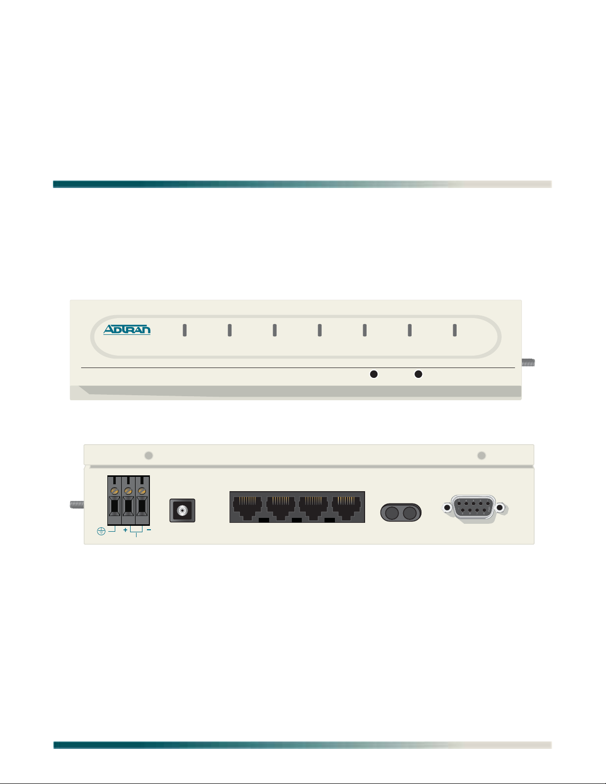
(QDFR) unit. The QDFR (P/N 1181307L7) front panel is illustrated in Figure 1. The QDFR rear
panel is illustrated in Figure 2.
QDFR
1181307L7
OPTICS
DS1 1
DS1 2
DS1 3
DS1 4
CH SELECT LBK
LBK
NEND(Y)
FENG(G)
TEST
TERM(R)
MON(G)
Figure 1. QDFR Front Panel
BATTERY
FIBER
OPTICS
24V-48V
DS1
4
DS1
3
DS1 2DS1
1
TX RX
Complies with 21CFR, SubchapterJ,
Parts 1010 and 1040.
ADTRAN, Huntsville Al. 35814 USA
CRAFT
Figure 2. QDFR Rear Panel
Description
The QDFR is a customer premise fiber optic access unit. The QDFR is designed to provide four
T1 interfaces that can be multiplexed together over a single mode fiber optic cable to a Total
Access 3000 Quad Fiber Central Office (QDFC) Module (P/N 1181308L7).
The QDFR is specifically designed to provide a high degree of resistance to damage typically
caused by Ground Potential Rises (GPRs). This is accomplished by having the network
interface optically isolated from the customer side and the DS-1 interfaces having over 6
kilovolts of isolation with respect to ground. The QDFR is virtually immune to the effects of
GPRs compared to other network interface equipment.
61181307L7-5E 1

Quad Fiber Remote (QDFR) Unit Installation and Maintenance Practice
Features
The QDFR provides the following features:
• Software provisionable via menu access (no onboard switches)
• Front panel indicators for the following:
– Optical port status
– T1 status for all channels
– Loopback status
–Test port operation
• Operation over extended temperature range of –40°C to +65°C
• Optical interface consisting of a single mode transceiver module comprised of a single fiber
transmitter and an SC receptacle
• Optical interface port support for flat SC-type optical connectors
• Single fiber optical interface
• Operating wavelengths:
– 1310 nm for the receiver
– 1550 nm for the transmitter
Compliance
The QDFR is NRTL listed to UL 60950. The QDFR is compliant to IEC-60825 Class 1 and is
also compliant with 21CFR 1040.10 and 1040.11 except for deviations pursuant to Laser
Notice No. 50, dated July 26, 2001. The QDFR is intended for use in restricted access
locations only.
Table 1 provides compliance codes for the QDFR.
Table 1. Compliance Codes
Code Input Output
Power Code (PC) F C
Telecommunication Code (TC) – –
Installation Code (IC) A –
The DS1 interfaces for the QDFR are to be connected to intra-building wiring only.
CAUTION
Per GR-1089-CORE October 2002, Section 9, this system is
designed and intended only for installation in a DC-C (common)
Bonding and Grounding system. It is not intended or designed for
installation in a DC-I (isolated) Bonding and Grounding system.
2 61181307L7-5E

Installation
INSTALLATION
C A U T I O N !
SUBJECT TO ELECTROSTATIC DAMAGE
OR DECREASE IN RELIABILITY.
HANDLING PRECAUTIONS REQUIRED.
After unpacking the QDFR, inspect it for damage. If damage has occurred, file a claim with the
carrier then contact ADTRAN Customer Service. Refer to “Appendix C, Warranty” for further
information. If possible, keep the original shipping container for returning the QDFR for repair
or for verification of shipping damage.
SHIPPING CONTENTS
The contents include the following items:
•QDFR Unit
• Quad Fiber Remote (QDFR) Unit Job Aid (P/N 61181307L7-22)
CAUTION
Electronic modules can be damaged by ESD. When handling modules, wear an antistatic discharge wrist strap to prevent damage to
electronic components. Place modules in antistatic packing material when transporting or storing. When working on modules,
always place them on an approved antistatic mat that is electrically
grounded.
Installing the QDFR
To install the QDFR, perform the following steps:
1. Place the unit in a location where a DC power source is available. This unit operates
within a voltage range of –24 VDC to –48 VDC.
2. Using the hex nut and lock washer supplied with the QDFR, attach a grounding strap to
the grounding lug on the left side of the QDFR chassis. Finger-tighten only.
3. Conned power to the QDFR by connecting the plus (+), minus (–), and ground wires to a
three-position terminal block located at the left of the backplane (Figure 2). The DS1 loop
connections are made through four RJ-48C type connectors. Single-mode fiber is
connected to the SC-type connector located at the right of the backplane.
When the QDFR first powers up, the unit initializes a self test that lasts for approximately 30
seconds. After the self test is completed, the LEDs reflect the current status of the unit.
Front Panel LEDs
The QDFR provides front panel LEDs to display status information for the unit. Table 2 lists
the front panel LEDs and their indications.
61181307L7-5E 3

Quad Fiber Remote (QDFR) Unit Installation and Maintenance Practice
Table 2. Front Panel LEDs
Label Indications Description
OPT
DS1 (1-4)
LBK
NEND/FEND
TERM/MON
z
z
/
{
z
z
z
/
5
{
z
z
z
z
Green
Red
Flashing (Red/Green)
Off
Green
Yellow
Red
Flashing (Red/Green)
Flashing
Off
Green
Yellow
Green
Red
Front Panel Pushbuttons
Signal present
Loss of signal
Errored second
Port Service state set to Out of Service: Unassigned
Good signal present
Near-end or Far-end loopback present
Loss of signal
Errored second
Port selected for loopback switches and test access;
flashing state times out 1 minute after channel
selection is made
No loopback present on selected channel
Far-end loopback present on selected channel
Near-end loopback present on selected channel
Test jack in Monitor mode on selected channel
Test jack enabled for Terminate mode (intrusive
access) on selected channel
The QDFR has two pushbuttons located on the front panel:
• Channel Select (
•Loopback (
To initiate a channel loopback at the QDFR, press
flashing, then press
CH SELECT)
LBK)
CH SELECT until the desired channel LED is
LBK to initiate the loopback.
NOTE
This selection only pertains to the test jack and the pushbuttons.
The user may continue to initiate or terminate any loopback on any
channel via the craft port.
• To initiate a loopback at the QDFC, press the
• To terminate active loopback(s), press the
LBK pushbutton for at least 3 seconds.
LBK switch while any loopback is active.
NOTE
All loopbacks initiated by the QDFR pushbuttons are bilateral.
Data from the port input is sent to the port output, and data from
the network (fiber) is sent back to the fiber.
4 61181307L7-5E
Loop Connections
T
LOOP CONNECTIONS
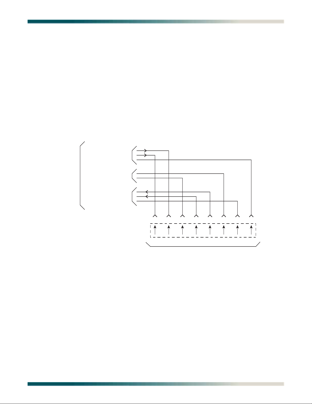
The T1 loop connections are made through four RJ-48C type connectors. For each connector,
transmit tip and ring are on pins 5 and 4, and receive tip and ring are on pins 2 and 1, respectively. The single-mode fiber is connected to the SC connector located on the back panel of the
unit.
OPERATION
The Quad Fiber Remote (QDFR) Unit provides a platform to exchange data between four Tls
and an optical fiber interface. The customer data connection is via the RJ-48C connectors on
the unit. An optical fiber interface is provided for communication with the loop. The Quad
Fiber Remote (QDFR) Unit operates with a QDFC module at the other end of the fiber optic
cable. The figure below illustrates the pin-out configuration for the RJ-48C connectors.
T
Receive from Network
R
o Network
Reserved for Future Use
Transmit to Network
Miniature 8-Position Plug
T1
R1
12345678
R T R1 T1
To Registered Terminal Equipment
Figure 3. RJ-48C Pinout Configuration
Power Interface
The power for the QDFR can be supplied through a –48 VDC supply connected to the back of
the QDFR. The QDFR can be powered from –24 VDC to –48 VDC.
Diagnostics
There are several options available for diagnostics:
• Front panel LEDs (see Table 2 on page 4)
• “Loopback and Test Commands Menu” on page 12
• “Performance History Menu” on page 16
• “Troubleshooting Menu” on page 22
61181307L7-5E 5

Quad Fiber Remote (QDFR) Unit Installation and Maintenance Practice
PROVISIONING
The QDFR provides the ability to change provisioning options. Table 3 lists the valid settings
and defaults for the provisioning options. Provisioning options are set independently for each
of the DS1s.
Table 3. QDFR
Option Settings (Default in BOLD)
Provisioning – Channel Options
DSX-1 Line Buildout 0-133 Feet
DSX-1/DS1 Line Code AMI;
NIU Loopback Disabled
Loopback Timeout None
DS1 TX Level 0 dB
Customer Loss Indicator AIS
Provisioning Menu Defaults
133-266 Feet
266-399 Feet
399-533 Feet
533-655 Feet
B8ZS
Enabled
120 Min
–7.5 dB
–15 dB
Loopback
6 61181307L7-5E

Menu Structure
MENU STRUCTURE
The menu structure for the QDFR is a layered menu tree. Each layer of the menu tree is
displayed as a menu or a screen.
Menu
A menu is a display that provides numbered selections that are used to navigate to related
menus, modify provisioning information, or display information screens. A menu can contain
the following objects:
• Menu Option: A menu option is indicated by a number, which when selected navigates the
display to another menu layer or is used to change the option setting.
• Read-only Field: A read-only field displays information that cannot be changed. The
information displayed in a read-only field can be static or can be automatically updated by
the QDFR.
• Read-write Field: A read-write field displays information that when selected can be
modified.
• Hot Key: A hot key is a key or combination of keys that are assigned to a function. Hot keys
are indicated by the required key(s) and a brief description (i.e., N - Next Channel).
Screen
A screen is a display that usually indicates the end of a menu tree path. A screen can contain
the following objects:
• Read-only Field: A read-only field displays information that cannot be changed. The
information displayed in a read-only field can be static or can be automatically updated by
the QDFR.
• Read-write Field: A read-write field displays information that when selected can be
modified.
• Hot Key: A hot key is a key or combination of keys that are assigned to a function. Hot keys
are indicated by the required key(s) and a brief description (i.e., N - Next Channel).
MENU NAVIGATION
Basic menu navigation is accomplished by selecting the desired option number and then
pressing
ENTER. To return to the previous menu, press the ESC (escape) key.
61181307L7-5E 7
Loading...