


AD-78
(Gas/Electric/Steam)
Installation Manual
WARNING: For your safety the information in this manual must be followed to minimize the risk of fire or explosion or to prevent property damage, personal injury or death.
Do not store or use gasoline or other flammable vapor and liquids in the vicinity of this or any other appliance.
WHAT DO YOU DO IF YOU SMELL GAS
*Do not try to light any appliance.
*Do not touch any electrical switch; do not use any phone in your building.
*Clear the room, building or area of all occupants.
*Immediately call your gas supplier from a neighbor's phone. Follow the gas supplier's instructions.
*If you cannot reach your gas supplier, call the fire department.
Installation and service must be performed by a qualified installer, service agency or the gas supplier.
For replacement parts, contact the distributor from which the dryer was purchased or
American Dryer Corporation
88 Currant Road
Fall River MA 02720-4781
Telephone: (508) 678-9010 / Fax: (508) 678-9447 E-mail: service@amdry.com
122497PSS/tf |
ADC Part No. 113028 |
Retain This Manual In A Safe Place For Future Reference
American Dryer Corporation products embody advanced concepts in engineering, design, and safety. If this product is properly maintained, it will provide many years of safe, efficient, and trouble-free operation.
ONLY properly licensed technicians should service this equipment.
OBSERVE ALL SAFETY PRECAUTIONS displayed on the equipment or specified in the installation/operator's manual included with the dryer.
WARNING: UNDER NO CIRCUMSTANCES should the door switch or the heat circuit devices ever be disabled.
WARNING: The dryer must never be operated with any of the back guards, outer tops, or service panels removed. PERSONAL INJURY or FIRE COULD RESULT.
We have tried to make this manual as complete as possible and hope you will find it useful. ADC reserves the right to make changes from time to time, without notice or obligation, in prices, specifications, colors, and material, and to change or discontinue models.
Important
For your convenience, log the following information:
DATE OF PURCHASE |
|
MODEL NO. |
AD-78
DISTRIBUTORS NAME
Serial Number(s)
Replacement parts can be obtained from your distributor or the ADC factory. When ordering replacement parts from the factory, you can FAX your order to ADC at (508) 678-9447 or telephone your orders directly to the ADC Parts Department at (508) 678-9000. Please specify the dryer model number and serial number in addition to the description and part number, so that your order is processed accurately and promptly.
The illustrations on the following pages may not depict your particular dryer exactly. The illustrations are a composite of the various dryer models. Be sure to check the descriptions of the parts thoroughly before ordering.
“IMPORTANT NOTE TO PURCHASER”
Information must be obtained from your local gas supplier on the instructions to be followed if the user smells gas. These instructions must be posted in a prominent location near the dryer.
IMPORTANT
YOU MUST DISCONNECT and LOCKOUT THE ELECTRIC SUPPLY and THE GAS SUPPLY or THE STEAM SUPPLY BEFORE ANY COVERS or GUARDS ARE REMOVED FROM THE MACHINE TO ALLOW ACCESS FOR CLEANING, ADJUSTING, INSTALLATION, or TESTING OF ANY EQUIPMENT per OSHA (Occupational Safety and Health Administration) STANDARDS.
CAUTION
LABEL ALL WIRES PRIOR TO DISCONNECTION WHEN SERVICING CONTROLS. WIRING ERRORS CAN CAUSE IMPROPER AND DANGEROUS OPERATION.
VERIFY PROPER OPERATION AFTER SERVICING.
CAUTION
DRYER(S) SHOULD NEVER BE LEFT UNATTENDED WHILE IN OPERATION.
WARNING
CHILDREN SHOULD NOT BE ALLOWED TO PLAY ON OR NEAR THE DRYER(S).
CHILDREN SHOULD BE SUPERVISED IF NEAR DRYER(S) IN OPERATION.
WARNING
The dryer must never be operated with any of the back guards, outer tops, or service panels removed. PERSONAL INJURY or FIRE COULD RESULT.

FOR YOUR SAFETY
DO NOT STORE OR USE GASOLINE OR OTHER FLAMMABLE VAPOR AND LIQUIDS IN THE VICINITY OF THIS OR ANY OTHER APPLIANCE.
DO NOT DRY MOP HEADS IN THE DRYER.
DO NOT USE DRYER IN THE PRESENCE OF DRY CLEANING FUMES.
IMPORTANT
PLEASE OBSERVE ALL SAFETY PRECAUTIONS displayed on the equipment and/or specified in the installation/operator's manual included with the dryer.
Dryer(s) must not be installed or stored in an area where it will be exposed to water and/or weather.
The wiring diagram for the dryer is located in the front electrical control box area.
Table of Contents |
|
SECTION I |
|
IMPORTANT INFORMATION ............................................................................... |
3 |
A. Receiving and Handling ............................................................................................................... |
3 |
B. Safety Precautions ....................................................................................................................... |
4 |
SECTION II |
|
SPECIFICATIONS and DIMENSIONS ................................................................. |
6 |
A. Specifications (Gas and Steam Models) ....................................................................................... |
6 |
B. Component Identification ............................................................................................................. |
8 |
SECTION III |
|
INSTALLATION REQUIREMENTS .................................................................... |
10 |
A. Location Requirements .............................................................................................................. |
10 |
B. Unpacking/Setting Up ............................................................................................................... |
11 |
C. Dryer Enclosure requirements .................................................................................................... |
12 |
D. Fresh Air Supply ....................................................................................................................... |
13 |
E. Exhaust Requirements ............................................................................................................... |
15 |
F. Electrical Information ................................................................................................................ |
19 |
G. Gas Information ........................................................................................................................ |
26 |
H. Steam Information ..................................................................................................................... |
30 |
I. Preparation For Operation/Start-up .......................................................................................... |
35 |
J. Preoperational Tests .................................................................................................................. |
36 |
K. Preoperational Instructions ........................................................................................................ |
38 |
L. Shut Down Instructions .............................................................................................................. |
39 |
SECTION IV |
|
SERVICE/PARTS INFORMATION ...................................................................... |
40 |
A. Service ..................................................................................................................................... |
40 |
B. Parts ......................................................................................................................................... |
40 |
SECTION V |
|
WARRANTY INFORMATION .............................................................................. |
41 |
A. Returning Warranty Card(s) ...................................................................................................... |
41 |
B. Parts ......................................................................................................................................... |
41 |
C. Returning Warranty Card(s) ...................................................................................................... |
41 |
SECTION VI |
|
ROUTINE MAINTENANCE .................................................................................. |
43 |
A. Cleaning ................................................................................................................................... |
43 |
B. Adjustments .............................................................................................................................. |
44 |
SECTION VII |
|
TROUBLESHOOTING ............................................................................................ |
45 |
Microprocessor (Computer) Models ................................................................................... |
47 thru 57 |
Timer Models ..................................................................................................................... |
57 thru 64 |
SECTION VIII |
|
REVERSING TIMER SPIN/DWELL ADJUSTMENTS .................................... |
65 |
SECTION IX |
|
DATA LABEL LOCATION/INFORMATION ...................................................... |
66 |
SECTION X |
|
PROCEDURE FOR FUNCTIONAL CHECK OF REPLACEMENT |
|
COMPONENTS ........................................................................................................ |
68 |

SECTION I
IMPORTANT INFORMATION
A. RECEIVING and HANDLING
The dryer is shipped in a protective stretch wrap cover with protective cardboard corners and top cover (or optional box) as a means of preventing damage in transit. Upon delivery, the dryer and/or packaging, and wooden skid should be visually inspected for shipping damage. If any damage whatsoever is noticed, inspect further before delivering carrier leaves.
Dryers damaged in shipment:
1.ALL dryers should be inspected upon receipt and before they are signed for.
2.If there is suspected damage or actual damage, the trucker's receipt should be so noted.
3.If the dryer is damaged beyond repair, it should be refused. Those dryers which were not damaged in a damaged shipment should be accepted, but the number received and the number refused must be noted on the receipt.
4.If you determine that the dryer was damaged after the trucker has left your location, you should call the delivering carrier's freight terminal immediately and file a claim. The freight company considers this concealed damage. This type of freight claim is very difficult to get paid and becomes extremely difficult when more than a day or two passes after the freight was delivered. It is your responsibility to file freight claims. Dryer/parts damaged in transit cannot be claimed under warranty.
5.Freight claims are the responsibility of the consignee, and ALL claims must be filed at the receiving end. ADC assumes no responsibility for freight claims or damages.
6.If you need assistance in handling the situation, please contact the ADC Traffic Manager at (508) 678-9000.
IMPORTANT: The dryer must be transported and handled in an upright position at all times.
3

B. SAFETY PRECAUTIONS
WARNING: For your safety, the information in this manual must be followed to minimize the risk of fire or explosion or to prevent property damage, personal injury, or loss of life.
WARNING: The dryer must never be operated with any of the back guards, outer tops, or service panels removed. PERSONAL INJURY or FIRE COULD RESULT.
1.DO NOT store or use gasoline or other flammable vapors and liquids in the vicinity of this or any other appliance.
2.Purchaser/user should consult the local gas supplier for proper instructions to be followed in the event the user smells gas. The instructions should be posted in a prominent location.
3.WHAT TO DO IF YOU SMELL GAS...
a.DO NOT try to light any appliance.
b.DO NOT touch any electrical switch.
c.DO NOT use any phone in your building.
d.Clear the room, building, or area of ALL occupants.
e.Immediately call your gas supplier from a neighbor's phone. Follow the gas supplier's instructions.
f.If you cannot reach your gas supplier, call the fire department.
4.Installation and service must be performed by a qualified installer, service agency, or gas supplier.
5.Dryer(s) must be exhausted to the outdoors.
6.Although ADC produces a very versatile machine, there are some articles that, due to fabric composition or cleaning method, should not be dried in it.
WARNING: Dry only water-washed fabrics. DO NOT dry articles spotted or washed in dry cleaning solvents, a combustible detergent, or "all purpose" cleaner. EXPLOSION
COULD RESULT.
WARNING: DO NOT dry rags or articles coated or contaminated with gasoline, kerosene, oil, paint, or wax. EXPLOSION COULD RESULT.
WARNING: DO NOT dry mop heads. Contamination by wax or flammable solvent will create a fire hazard.
WARNING: DO NOT use heat for drying articles that contain plastic, foam, sponge rubber, or similarly textured rubberlike materials. Drying in a heated basket (tumbler) may damage plastics or rubber and also may be a fire hazard.
4

7.A program should be established for the inspection and cleaning of lint in the burner area, exhaust duct work, and area around the back of the dryer. The frequency of inspection and cleaning can best
be determined from experience at each location.
WARNING: The collection of lint in the burner area and exhaust duct work can create a potential fire hazard.
8.For personal safety, the dryer must be electrically grounded in accordance with local codes and/or the NATIONAL ELECTRIC CODE ANSI/NFPA NO. 70-LATEST EDITION.
NOTE: Failure to do so will VOID THE WARRANTY.
9.UNDER NO CIRCUMSTANCES should the dryer door switches, lint drawer switch, or heat safety circuit, ever be disabled.
WARNING: PERSONAL INJURY or FIRE COULD RESULT.
10.This dryer is not to be used in the presence of dry cleaning solvents or fumes.
11.Remove articles from the dryer as soon as the drying cycle has been completed.
WARNING: Articles left in the dryer after the drying and cooling cycles have been complete can create a fire hazard.
12. READ and FOLLOW ALL CAUTION and DIRECTION LABELS ATTACHED TO THE DRYER.
WARNING: YOU MUST DISCONNECT and LOCKOUT THE ELECTRIC SUPPLY and THE GAS SUPPLY or THE STEAM SUPPLY BEFORE ANY COVERS or GUARDS ARE REMOVED FROM THE MACHINE TO ALLOW ACCESS FOR CLEANING, ADJUSTING, INSTALLATION, or TESTING OF ANY EQUIPMENT per OSHA (Occupational Safety and Health Administration)
STANDARDS.
5

SECTION II
SPECIFICATIONS/COMPONENT IDENTIFICATION
A. SPECIFICATIONS
BASKET (TUMBLER) DIAMETER |
|
44-1/2" |
|
|
113 cm |
||||
BASKET (TUMBLER) DEPTH |
|
24-7/8" |
|
|
63.2 cm |
||||
BASKET (TUMBLER) MOTOR |
|
1 HP* |
|
|
.746 kw |
||||
DOOR OPENING (DIAMETER) |
|
31-3/8" |
|
|
79.7 cm |
||||
BASKET (TUMBLER) VOLUME |
22.4 cu. ft. |
|
|
.634 cu.m. |
|||||
DRYERS PER 20'/40'' CONTAINER |
|
|
|
10/20 |
|
|
|||
|
|
|
|
|
|
|
|
|
|
DRYERS PER 45'/48' TRUCK |
|
|
|
24/24 |
|
|
|||
|
|
|
|
|
|
|
|
||
|
VOLTAGE AVAILABLE |
|
120 / 208 / 240 / 480v / 1, 3ø / 50/60Hz |
||||||
|
|
|
|
|
|
|
|
|
|
|
APPROX. WEIGHT (UNCRATED) |
|
895 lbs. |
|
|
407 kg |
|||
Gas |
APPROX. WEIGHT (CRATED) |
|
950 lbs. |
|
|
432 kg |
|||
HEAT INPUT |
|
204,000 btu/hr |
|
51,408 kcal/hr |
|||||
|
AIRFLOW |
|
|
1,200 cfm |
|
|
33.98 cmm |
||
|
Inlet Pipe Size |
|
|
3/4"** |
|
|
1.91 cm |
||
Electric |
VOLTAGE AVAILABLE |
|
120 / 208 / 240 / 480v / 1, 3ø / 50/60Hz |
||||||
|
|
|
|
|
|
|
|
|
|
AIRFLOW |
|
|
1,200 cfm |
|
|
33.98 cmm |
|||
|
APPROX. WEIGHT (UNCRATED) |
|
895 lbs. |
|
|
407 kg |
|||
|
APPROX. WEIGHT (CRATED) |
|
950 lbs. |
|
|
432 kg |
|||
|
|
|
|
|
|
|
|
|
|
|
VOLTAGE AVAILABLE |
|
120 / 208 / 240 / 480v / 1, 3ø / 50/60Hz |
||||||
|
|
|
|
|
|
|
|
|
|
|
APPROX. WEIGHT (UNCRATED) |
|
980 lbs |
|
|
445 kg |
|||
|
APPROX. WEIGHT (CRATED) |
|
1,130 lbs. |
|
|
514 kg |
|||
|
AIRFLOW |
|
|
1,200 cfm |
|
|
33.98 cmm |
||
Steam |
COMPRESSED AIR VOLUME |
BOILER HP |
|
|
.02 cmh |
||||
|
|
.75 cfh |
|
|
|||||
|
COMPRESSED AIR CONNECTION |
1/8" F.P.T. |
|
|
.318 cm |
||||
|
STEAM COMSUMPTION |
NORMAL LOAD |
|
|
|
|
|||
|
|
|
|
|
|
|
|||
|
|
|
|
|
|
|
|
|
|
|
238.7 lbs/hr |
108.3 kg/hr |
|
7 |
|
|
|
|
|
|
OPERATING STEAM PRESSURE |
STEAM SUPPLY |
|
STEAM RETURN |
|||||
|
|
|
|
|
|
|
|
|
|
|
125 psi max |
8.6 bar |
1" |
|
2.54 cm |
|
1" |
|
2.54 cm |
|
|
|
|
|
|
|
|
|
|
Shaded areas are stated in metric equivalents.
*For non-reversing models.
**A minimum of 3/4" pipe must be supplied to the gas inlet for each dryer.
IMPORTANT: Steam dryers must be provided with a clean, dry, regulated 80 PSI (+/- 10 PSI) air supply.
NOTE: ADC reserves the right to make changes in specifications at any time, without notice or obligation.
6
Specifications*
ADG-78 (Gas)
ADE-78 (Electric)
*Specifications for the ADS-78 (steam model) were not available at time of printing...for information contact the factory.
NOTE: ADC reserves the right to make changes in specifications at any time, without notice or obligation.
7
B. COMPONENT IDENTIFICATION
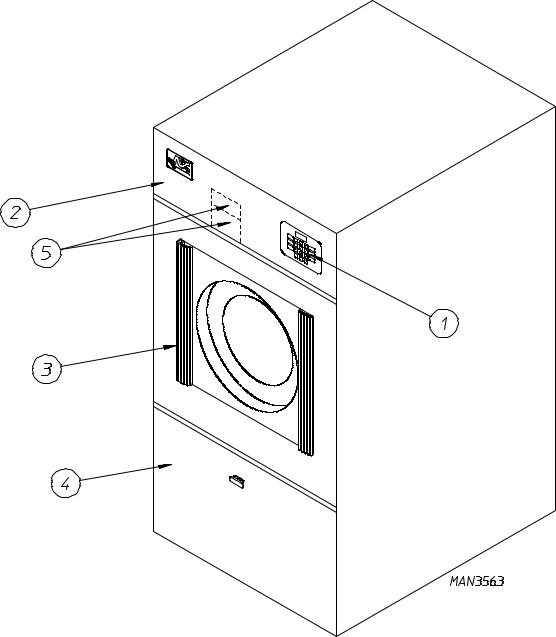
1. Dryer Front View
Illus. No. Description
1Controls
2Control (top access) Door Assembly
3Main Door Assembly
4Lint Compartment Area (lint screen located behind door)
5Data Label and Installation Label (located behind control [service] door)
8
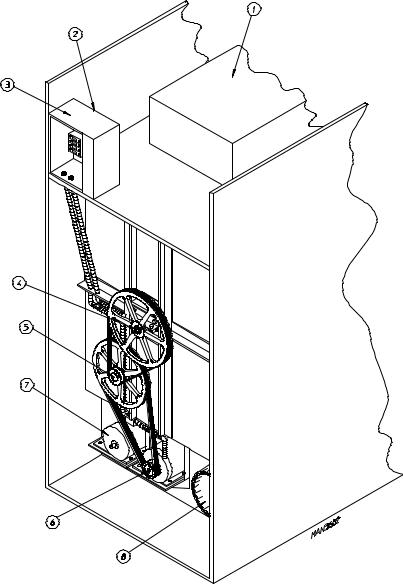
2. Dryer Rear View
Illus. No. Description
1Heating Unit
21/8" Compressed Air Supply Inlet
(behind Electric Service Relay Box for Steam Models ONLY)
3* |
Electric Service Relay Box |
4Tumbler Bearing Mount Assembly
5Idler Bearing Mount Assembly
6Basket (Drive) Motor Assembly (for Reversing Models ONLY)
7Blower Motor Assembly
8Dryer Exhaust
*Electric service connections for Gas Models and Steam Models are made in this box.
9

SECTION III
INSTALLATION PROCEDURES
Installation should be performed by competent technicians in accordance with local and state codes. In the absence of these codes, the installation must conform to applicable American National Standards: National Fuel Gas Code ANSI.Z223.1-LATEST EDITION and/or National Electric Code ANSI/NFPA NO. 70-LATEST EDITION.
A. LOCATION REQUIREMENTS
Before installing the dryer, be sure the location conforms to local codes and ordinances. In the absence of such codes or ordinances the location must conform with the National Fuel Gas Code ANSI.Z223.1-LATEST EDITION.
1.The dryer must be installed on a sound level floor capable of supporting its weight. It is recommended that carpeting be removed from the floor area that the dryer is to rest on.
2.The dryer must not be installed or stored in an area where it will be exposed to water and/or weather.
3.The dryer is for use in noncombustible locations.
4.Provisions for adequate air supply must be provided as noted in this manual (refer to Fresh Air Supply in
Section D).
5.Clearance provisions must be made from combustible construction as noted in this manual (refer to Dryer Enclosure Requirements in Section C).
6.Provisions must be made for adequate clearances for servicing and for operation as noted in this manual (refer to Dryer Enclosure Requirements in Section C).
7.Dryer must be exhausted to the outdoors (refer to Exhaust Requirements in Section E).
8.Dryer must be located in an area where correct exhaust venting can be achieved as noted in the manual (refer to Exhaust Requirements in Section E).
IMPORTANT: Dryer should be located where a minimum amount of exhaust duct will be necessary.
10

B. UNPACKING/SETTING UP
Remove protective shipping material (i.e., plastic wrap, and/or optional shipping box) from dryer.
IMPORTANT: Dryer must be transported and handled in an upright position at ALL times.
The dryer can be moved to its final location while still attached to the skid or with the skid removed. To un-skid the dryer, locate and remove the four (4) bolts securing the base of the dryer to the wooden skid. Two (2) are at the rear base (remove the back panel for access), and two (2) are located in the bottom of the lint chamber. To remove the two (2) bolts located in the lint chamber area, remove the lint door.
To increase bearing life and improve efficiency, the dryer should be tilted slightly to the rear.
The basket (tumbler) is supported during shipping by a wooden block. REMOVE THIS BLOCK BEFORE STARTING THE DRYER.
IMPORTANT: For microprocessor (computer) models, this wooden block must be removed before connecting power to the dryer or irreparable damage to the basket (tumbler) will result.
The lint coops of ALL AD-78 dryers are supported during shipping by a bracket. REMOVE THIS BRACKET BEFORE STARTING THE DRYER.
11

C. DRYER ENCLOSURE REQUIREMENTS
Bulkheads and partitions should be made of noncombustible materials and must be located a minimum of twelve (12) inches (18-inches or more is recommended for ease of installation, maintenance , and service) above the dryer outer top, except along the front of the dryer which may be partially closed in if desired. The clearance between the bulkhead header and the dryer must be a minimum of four (4) inches and must not extend more than four (4) inches to the rear of the front. The bulkhead facing must not be closed in all the way to the top of the dryer. A one (1) inch clearance is required.
NOTE: Allowances must be made for opening the control door.
Dryers may positioned side wall to side wall. However, a 1/16" minimum allowance must be made for opening and closing of the control door and the lint door. It is suggested that the dryer be positioned about two (2) feet away from the nearest obstruction for ease of installation, maintenance, and service (to be measured from the back guard. (Refer to the illustration above for details.)
NOTE: Air considerations are important for proper and efficient operation.
12
IMPORTANT: Even though a minimum of only 12-inches is required, 18-inches or more is suggested. The additional clearance is advantageous for ease of installation and service.
IMPORTANT: When fire sprinkler systems are located above the dryers, a minimum of 18-inches above the dryer console (module) is required. Dryers may be positioned side wall to side wall however, a 1/16" minimum allowance is required between dryers (or wall) for ease of installation and maintenance. Allowances must be made for the opening and closings of the control door and the lint door.
D. FRESH AIR SUPPLY
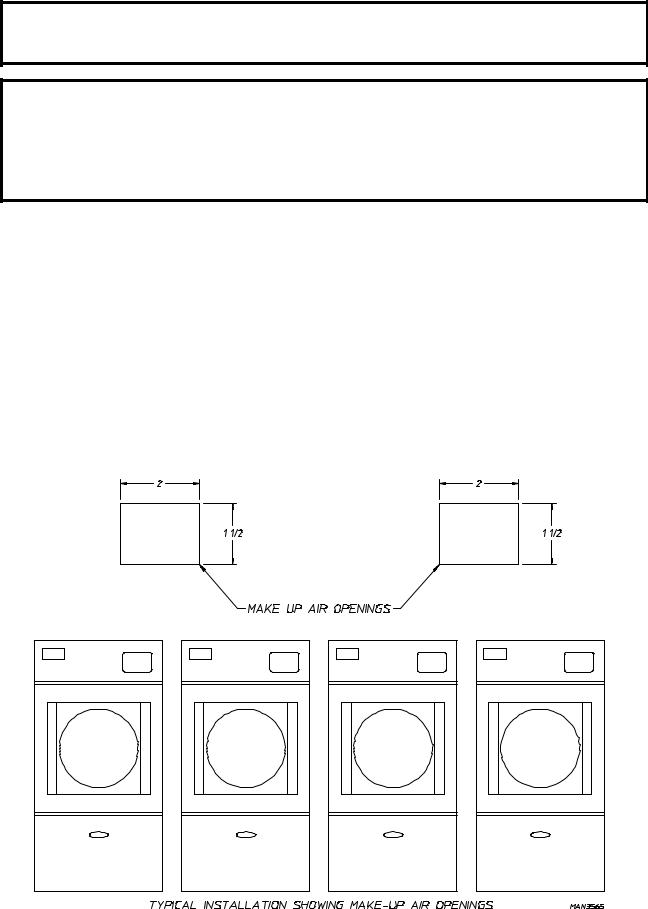
When the dryer is operating, it draws in room air, heats it, passes this air through the basket (tumbler), and exhausts it out of the building. Therefore, the room air must be continually replenished from the outdoors. If the make-up air is inadequate, drying time and drying efficiency will be adversely affected. Ignition problems and sail switch "fluttering" problems may result, as well as premature motor failure from overheating.
Air supply (make-up air) must be given careful consideration to assure proper performance of each dryer. An unrestricted source of air is necessary for each dryer. An air flow of 1,200 cfm (cubic feet per minute) must be supplied to each gas and electric dryer and 1,350 cfm (cubic feet per minute) must be supplied to each steam dryer. As a general rule, an unrestricted air entrance from the outdoors (atmosphere) of a minimum of 1-1/2 square feet is required for each dryer.
13

To compensate for the use of registers or louvers used over the openings, this make-up air must be increased by approximately thirty-three percent (33%). Make-up air openings should not be located in an area directly near where exhaust vents exit the building.
It is not necessary to have a separate make-up air opening for each dryer. Common make-up air openings are acceptable. However, they must be set up in such a manner that the make-up air is distributed equally to ALL the dryers.
EXAMPLE: For a bank of four (4) dryers, two (2) unrestricted openings measuring 2 feet by 1-1/2 feet (6 square feet) is acceptable.
Allowances must be made for remote or constricting passageways or where dryers are located at excessive altitudes or predominantly low pressure areas.
IMPORTANT: Make-up air must be provided from a source free of dry cleaning solvents fumes. Make-up air that is contaminated by dry cleaning solvent fumes will result in irreparable damage the motors and other dryer components.
NOTE: Component failure due to dry cleaning solvent fumes will VOID THE WARRANTY.
14
E. EXHAUST REQUIREMENTS
1.General Exhaust Duct Work Information
Exhaust duct work should be designed and installed by a qualified professional. Improperly sized duct work will create excessive back pressure which results in slow drying, increased use of energy, overheating of the dryer, and shutdown of the burner by the airflow (sail) switches, burner hi-limits, or basket (tumbler) hi-heat thermostats.
CAUTION: DRYER MUST BE EXHAUSTED TO THE OUTDOORS.
CAUTION: IMPROPERLY SIZED OR INSTALLED EXHAUST DUCT WORK CAN CREATE A POTENTIAL FIRE HAZARD.
The duct work should be laid out in such a way that the duct work travels as directly as possible to the outdoors with as few turns as possible. Single or independent dryer venting is recommended.
Horizontal Venting:
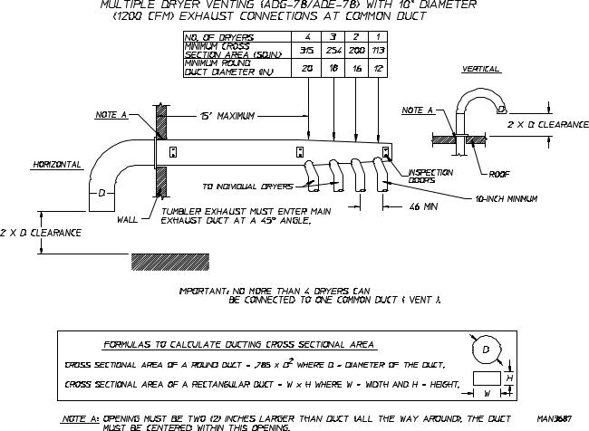
When single drying venting is used the length of duct work from the dryer to the outside exhaust outlet should not exceed fifteen (15) feet. The minimum diameter of this duct work must be at least 10-inches (even though the dryer exhaust duct for gas and electric dryers is only 8-inches). In the case of multiple (common) dryer venting, the distance from the last dryer to the outside exhaust outlet should not exceed (15) feet. The shape of the duct work is not critical so long as the minimum cross-sectional area is provided. It is suggested that the use of 90° turns be avoided; use 30° and/or 45° angles instead. The radius of the elbows should preferably be 1-1/2 times the diameter of the duct. Including basket (tumbler)/dryer elbow connections or elbows used for outside protection from the weather, no more than two (2) elbows should be used in the exhaust duct run. If more than two (2) elbows are used, the cross sectional area of the duct work must be increased. ALL duct work should be smooth inside with no projections from sheet metal screws or other obstructions which will collect lint. When adding ducts, the duct to be added should overlap the duct to which it is to be connected. ALL duct work joints must be taped to prevent moisture and lint from escaping into the building. Inspection door should be installed at strategic points in the exhaust duct work for periodic inspection and clean-out of lint from the duct work.
Vertical Venting:
When single dryer venting is used the length of the duct work from the dryer to the outside exhaust outlet should not exceed twenty (20) feet. The minimum diameter of this duct work must be at least 12inches (even though the dryer exhaust duct for gas and electric units is only 8-inches). In the case of multiple (common) dryer venting, the distance from the last dryer to the outside exhaust outlet should not exceed twenty (20) feet. The shape of the duct work is not so critical so long as the minimum cross sectional area is provided. It is suggested that the use of 90º turns be avoided; use 30º and/or 45º bends instead. The radius of the elbows should preferably be 1-1/2 times the diameter of the duct. ALL duct work should be smooth inside with no projections from sheet metal screws or other obstructions which will collect lint. When adding ducts, the duct to be added should overlap the duct to which it is to be connected. ALL duct work joints must be taped to prevent moisture and lint from escaping into the building. Inspection door should be installed at strategic points in the exhaust duct work for periodic inspection and clean-out of lint from the duct work.
IMPORTANT: Exhaust back pressure measured by a manometer in the exhaust duct should not exceed 0.3 inches of water column.
15
IMPORTANT: Minimum duct work diameter for horizontal venting is 10-inches and for vertical venting the minimum is 12-inches.
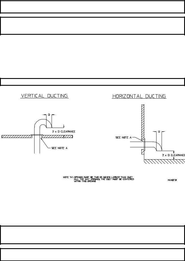
NOTE: Where the exhaust duct work passes through a wall, ceiling, or roof made of combustible materials, the opening must be 2-inches larger (all the way around) than the duct. The duct must be centered within this opening.
a.Outside Duct Work Protection
1)To protect the outside end of horizontal duct work from the weather, a 90° elbow bent downward should be installed where the exhaust exits the building. If the duct work travels vertically up through the roof, it should be protected from the weather by using a 180° turn to point the opening downward. In either case, allow at least twice the diameter of the duct between the duct opening and the nearest obstruction.
IMPORTANT: DO NOT use screens or caps on the outside of opening of exhaust duct work.
2.Single Dryer Venting
Where possible, it is suggested to provide a separate exhaust duct for each dryer. The exhaust duct should be laid out in such a way that the duct work travels as directly as possible to the outdoors with as few turns as possible. It is suggested that the use of 90° turns in the ducting be avoided; use 30° and/or 45° angles instead. The shape of the exhaust duct work is not critical so long as the minimum cross section area is provided.
IMPORTANT: Minimum duct size for a dryer that is vented horizontally is 10-inches for a round duct or an equivalent of 80 square inches. THE DUCT SIZE MUST
NOT BE REDUCED ANYWHERE DOWN STREAM OF THE DRYER.
IMPORTANT: Exhaust back pressure measured by a manometer at each basket (tumbler) exhaust duct area should not exceed 0.3 inches of water column.
16
IMPORTANT: Minimum duct size for a dryer that is vented vertically is 12-inches for a round duct or an equivalent of 120 square inches. THE DUCT SIZE MUST NOT BE
REDUCED ANYWHERE DOWN STREAM OF THE DRYER.
IMPORTANT: For extended duct work runs, the cross section area of the duct work can only be increased to an extent. When the duct work approaches the maximum limits noted in this manual, a professional heating venting air conditioning (HVAC) firm should be consulted for proper venting information.
ALL duct work should be smooth inside with no projections from sheet metal screws or other obstructions which will collect lint. When adding ducts, the duct to be added should overlap the duct to which it is to be connected. ALL duct work joints must be taped to prevent moisture and lint from escaping into the building. Inspection doors should be installed at strategic points in the exhaust duct work for periodic inspection and clean-out of lint from the duct work.
NOTE: Where the exhaust duct passes through a wall, ceiling, or roof made of combustible materials, the opening must be 2-inches larger (all the way around) than the duct. The duct must be centered within this opening.
a.Outside Duct Work Protection
1)To protect the outside end of horizontal duct work from the weather, a 90° elbow bent downward should be installed where the exhaust exits the building. If the duct work travels vertically up through the roof, it should be protected from the weather by using a 180° turn to point the opening downward. In either case, allow at least twice the diameter of the duct between the duct opening and the nearest obstruction.
IMPORTANT: DO NOT use screens or caps on the outside of opening of exhaust duct work.
17
18

F. ELECTRICAL INFORMATION
1.Electrical Requirements
It is your responsibility to have ALL electrical connections made by a properly licensed and competent electrician to assure that the electrical installation is adequate and conforms with local and state regulations or codes. In the absence of such codes, ALL electrical connections, material, and workmanship must conform to the applicable requirements of the National Electrical Code ANSI/NFPA NO.70-LATEST EDITION..
IMPORTANT: Failure to comply with these codes or ordinances, and/or the requirements stipulated in this manual can result in personal injury or component failure.
NOTE: Component failure due to improper installation will VOID THE WARRANTY.
Each dryer should be connected to an independently protected branch circuit. THE DRYER MUST BE
CONNECTED WITH COPPER WIRE ONLY. DO NOT use aluminum wire which could cause a fire hazard. The copper conductor wire/cable must be of proper ampicity and insulation in accordance with electric codes for making ALL service connections.
NOTE: The use of aluminum wire will VOID THE WARRANTY.
IMPORTANT: A separate circuit servicing each dryer must be provided.
19
 Loading...