


AD-310 Service Manual
American Dryer Corporation
88 Currant Road
Fall River, MA 02720-4781
Telephone: (508) 678-9000 / Fax: (508) 678-9447
e-mail: techsupport@amdry.com
123098DMG/abe |
ADC Part No. 450413 |
Retain This Manual In A Safe Place For Future Reference
American Dryer Corporation products embody advanced concepts in engineering, design, and safety. If this product is properly maintained, it will provide many years of safe, efficient, and trouble-free operation.
ONLY qualified technicians should service this equipment.
OBSERVE ALL SAFETY PRECAUTIONS displayed on the equipment or specified in the installation/operator's manual included with the dryer.
The following “FOR YOUR SAFETY” caution must be posted near the dryer in a prominent location.
FOR YOUR SAFETY
Do not store or use gasoline or other flammable vapors or liquids in the vicinity of this or any other appliance.
POUR VOTRE SÉCURITÉ
Ne pas entreposer ni utiliser d’essence ni d’autres vapeurs ou liquides inflammables dans le voisinage de cet appareil ou de yout autre appareil.
We have tried to make this manual as complete as possible and hope you will find it useful. ADC reserves the right to make changes from time to time, without notice or obligation, in prices, specifications, colors, and material, and to change or discontinue models.
Important
For your convenience, log the following information:
DATE OF PURCHASE MODEL NO. AD-310
DISTRIBUTORS NAME
Serial Number(s)
Replacement parts can be obtained from your distributor or the ADC factory. When ordering replacement parts from the factory, you can FAX your order to ADC at (508) 678-9447 or telephone your orders directly to the ADC Parts Department at (508) 678-9000. Please specify the dryer model number and serial number in addition to the description and part number, so that your order is processed accurately and promptly.
The illustrations on the following pages may not depict your particular dryer exactly. The illustrations are a composite of the various dryer models. Be sure to check the descriptions of the parts thoroughly before ordering.
“IMPORTANT NOTE TO PURCHASER”
Information must be obtained from your local gas supplier on the instructions to be followed if the user smells gas. These instructions must be posted in a prominent location near the dryer.
IMPORTANT
YOU MUST DISCONNECT and LOCKOUTTHE ELECTRIC SUPPLYand THE GAS SUPPLY or THE STEAM SUPPLY BEFORE ANY COVERS or GUARDS ARE REMOVEDFROMTHEMACHINETOALLOWACCESS FORCLEANING,ADJUSTING, INSTALLATION, or TESTING OFANY EQUIPMENT per OSHA (Occupational Safety and HealthAdministration) STANDARDS.
“Caution: Label all wires prior to disconnection when servicing controls. Wiring errors can cause improper operation.”
«Attention: Lor des opérations d’entretien des commandes étiqueter tous fils avant de les déconnecter. Toute erreur de câblage peut étre une source de danger et de panne.»
CAUTION
DRYERS SHOULD NEVER BE LEFT UNATTENDEDWHILE IN OPERATION.
WARNING
CHILDREN SHOULD NOT BEALLOWEDTO PLAYON OR NEAR THE DRYER(S). CHILDREN SHOULD BE SUPERVISED IFNEAR DRYERS IN OPERATION.
FOR YOUR SAFETY
DO NOT DRYMOPHEADS IN THE DRYER.
DO NOT USE DRYER IN THE PRESENCE OF DRYCLEANING FUMES.
WARNING
UNDER NO CIRCUMSTANCES should the door switch or the heat circuit devices ever be disabled.
WARNING
The dryer must never be operated with any of the back guards, outer tops, or service panels removed. PERSONALINJURY or FIRE COULD RESULT.
WARNING
DRYER MUST NEVER BE OPERATED WITHOUTTHE LINT FILTER/SCREEN IN PLACE, EVEN IF AN EXTERNAL LINT COLLECTION SYSTEM IS USED.
IMPORTANT
PLEASE OBSERVEALLSAFETYPRECAUTIONS displayed on the equipment and/or specified in the installation and operator's manual included with the dryer.
Dryers must not be installed or stored in an area where it will be exposed to water or weather.
The wiring diagram for the dryer is located in the front left electrical control box area.
Table of Contents |
|
AD-310 REFERENCE GUIDE |
|
Tumbler Section ............................................................................................................................. |
3 |
AD-310 REFERENCE GUIDE |
|
Base Section .................................................................................................................................. |
4 |
INTRODUCTION ............................................................................................................................... |
5 |
AD-310 MACHINE OPERATION SUMMARY ......................................................................... |
5 |
AD-310 OPERATOR CONTROLS/INDICATORS ...................................................................... |
5 |
AD-310 MACHINE OPERATION TROUBLESHOOTING INFORMATION ........................... |
8 |
SECTION I |
|
SAFETY PRECAUTIONS ................................................................................................................ |
16 |
SECTION II |
|
ROUTINE MAINTENANCE ........................................................................................................... |
18 |
A. Cleaning ................................................................................................................................... |
18 |
B. Lubrication ................................................................................................................................ |
20 |
C. Adjustments .............................................................................................................................. |
21 |
SECTION III |
|
SPECIFICATIONS and DIMENSIONS .......................................................................................... |
22 |
A. Specifications (Gas and Steam Models) ..................................................................................... |
22 |
B. Dimensions ............................................................................................................................... |
23 |
SECTION IV |
|
INSTALLATION REQUIREMENTS ............................................................................................. |
27 |
A. Enclosure/Air Supply/Exhaust Requirements .............................................................................. |
27 |
B. Electrical and Gas Requirements ................................................................................................ |
28 |
SECTION V |
|
COMPONENT DESCRIPTION/REPLACEMENT ....................................................................... |
29 |
A. Heat Section ............................................................................................................................. |
29 |
B. Troubleshooting The Direct Spark Ignition (DSI) System ............................................................ |
33 |
C. Natural Gas and L.P. (Liquid Propane) Gas Conversion Instructions .......................................... |
45 |
D. Steam Coil System Operation ................................................................................................... |
47 |
E. Sprinkler System Description ..................................................................................................... |
52 |
F. Tilting System Description .......................................................................................................... |
58 |
G. Air Jet Assembly ........................................................................................................................ |
65 |
H. Blower (Squirrel Cage Fan) Motor Assembly ............................................................................. |
67 |
I. Filter and Regulator Assembly ................................................................................................... |
74 |
J. Door Systems ............................................................................................................................ |
75 |
K. Control and Electrical System .................................................................................................... |
82 |
L. Tumbler (Basket) System ........................................................................................................... |
96 |
SECTION VI |
|
TROUBLESHOOTING .................................................................................................................. |
105 |
SECTION VII |
|
PROCEDURE FOR FUNCTIONAL CHECK OF REPLACEMENT |
|
COMPONENTS .............................................................................................................................. |
113 |

AD-310 Reference Guide
(Tumbler Section)
3
AD-310 Reference Guide
(Base Section)
4
INTRODUCTION
AD-310 MACHINE OPERATIONAL SUMMARY
The model AD-310 incorporates one (1) “EMERGENCY STOP (E-Stop) BUTTON” located centrally on the Right Front Control Door. This "RED" MUSHROOM PUSH-BUTTON is “PUSH TO STOP” the machine and “TURN TO RELEASE” or “PULL TO RELEASE” type control device. This button must be in the released mode to power the machine. The PHASE 5 MICROPROCESSOR CONTROLLER (Computer) display will light when the “EMERGENCY STOP (E-Stop) BUTTON” is in the released mode. To turn “ON” the control voltage, press the green “ON” push-button located on the Right Front Control Door.
The dryer has two (2) electronic controllers:
PHASE 5 MICROPROCESSOR CONTROLLER (Computer) - for drying material
MICRO-1 PLC (Programmable Logic Controller) - for loading, unloading auto doors, and burner status monitoring
The Phase 5 Microprocessor Controller (computer) only response to keypad (touchpad) commands when the tumbler section is level with the loading doors and lint drawer/basket door closed. Likewise, the Micro-1 PLC (Programmable Logic Controller) responses to load or unload selections when the dryer is not drying material.
AD-310 OPERATOR CONTROLS/INDICATORS
The Right Front Control Door incorporates the following operator controls/indicators: EMERGENCY STOP (E-Stop) BUTTON (Push To Stop/Turn or Pull To Release) JOG (Forward/Reverse Push-Buttons)
UNLOAD/DRY / LOAD (Selector Switch)
TILT FUNCTION (Off - On Selector Switch)
HEATER FAULT (Indicator/Reset Push-Button)
CONTROL POWER (Indicator/Control Power On Push-Button)
CONTROL POWER (Off Push-Button)
5

EMERGENCY (E-Stop) STOP BUTTON (Push To Stop/Turn To Release or Pull To Release)
This "red" mushroom push-button, located in the center of the Right Front Control Door almost directly under the Phase 5 Microprocessor Controller (computer) is a “Push To Stop” and “Turn To Release” type pushbutton. This button must be in the released mode to power the machine (enable the machine to run).
JOG (Forward/Reverse Push-Buttons)
These two (2) push-buttons, located towards the left side of the Right Front Control Door, are for either loading or unloading the tumbler. “JOG” functions are only enabled when the tumbler section is in a tilted position.
NOTE: There is a PLC (Programmable Logic Controller) controlled “DWELL TIME” between forward jog or reverse jog selection to prevent plug starting the tumbler drive motor.
LOAD / DRY / UNLOAD (Three [3] Position Selector Switch)
TILT (Off - On) (Two [2] Position Selector Switch)
The “LOAD / DRY / UNLOAD” and “TILT (Off - On)” selector switches work in conjunction with each other. If the “TILT” selector is in the “OFF” position, an “UNLOAD" or “LOAD” selection will open the front horizontal doors, allowing an operator to load or unload the tumbler in the level position.
NOTE: The “JOG” feature will respond in the level position. The Lint Drawer must be closed for the “JOG” feature to operate.
If the “TILT” selector is in the “ON” position, an “UNLOAD” selection will open the front vertical doors and tilt the tumbler section towards the front (Rear Up). Likewise, a “LOAD” selection will the front horizontal doors and tilt the tumbler section towards the rear (Front Up).
The “DRY” selection will bring the tumbler section to a level position and close the front horizontal doors. Once ALL safe conditions are met (i.e., front doors closed, lint drawer closed, machine level), an operator will be able to select a drying cycle on the Phase 5 Microprocessor Controller’s (computer) keypad (touchpad), located on the Right Front Control Door. Refer to the Phase 5 Operator’s manual for details.
HEATER FAULT (Indicator/Reset Button) for GAS MODELS ONLY
During a drying cycle the PLC (Programmable Logic Controller) monitors the status of the Phase 5 Microprocessor Controller’s (computer) “Heat On/Off” signal, the control status of the front and rear gas valves, and the state of both the front and rear burner air flow switches. If a fault is sensed, the "HEATER FAULT" indicator and “END OF CYCLE" indicator will begin to flash at a rate of one (1) per second. Both indicators will flash until the operator presses the “HEATER FAULT" reset push-button. For more details on “HEATER FAULT” refer to the operation section in this manual.
CONTROL POWER (On)
This "GREEN LIGHTED OPERATOR," located on the Right Front Control Door, is for enabling the dryer’s control voltage. This push-button must be “ON” for drying or load/unload function to occur.
6
CONTROL POWER (Off)
This "RED LIGHTED OPERATOR," located on the Right Front Control Door, is for disabling the dryer’s output control voltage. This push-button is mainly for use as a troubleshooting function.
END OF CYCLE / HEATER FAULT INDICATOR / AIR JET
This amber colored indicator located on the front/top of the dryer has two (2) functions:
1.To indicate that a drying cycle has been completed and that the dried material is ready for attention. Once the dryer is attended (i.e., lint drawer is opened, or the “UNLOAD - DRYLOAD” selector is turned to either the “UNLOAD” or “LOAD” position and the vertical doors open) the indicator will go off.
2.To indicate that a “HEATER FAULT” has occurred.
Note that during a “HEATER FAULT” this indicator will flash in conjunction with the “HEATER FAULT" indicator/reset push-button” located on the Right Front Control Door. Refer to the “HEATER FAULT" Indicator/Reset Push-Button explanation on the previous page (page 6), for more information concerning “HEATER FAULTS.”
3.The Air Jet will be activated at the end of the drying cycle when the “END OF CYCLE “light has been energized. The Air Jet will remain active for approximately thirty (30) seconds to remove lint which may have accumulated on the Blower Wheel (squirrel cage).
7
AD-310 MACHINE OPERATION TROUBLESHOOTING INFORMATION
END OF CYCLE/HEATER FAULT INDICATOR
The “END OF CYCLE” light located on the top/front of the dryer, is triggered by the Air Jet Signal of the Phase 5 Microprocessor Controller (computer) to the input of the PLC (Programmable Logic Controller). If this signal is not sensed by the PLC the light will not turn on. The “1-second flashing” is accomplished by a “Flasher Module” located on the Main Control Panel in the Right Front Control Cabinet. Refer to the electrical blueprints included with this machine for detailed signal routing.
The “HEATER FAULT” signal is an output of the PLC (Programmable Logic Controller) to the “END OF CYCLE” light. A “HEATER FAULT” is an indication that a malfunction has occurred in the “Gas Heat Circuit” and needs attention. Refer to the “HEATER FAULT” explanations on page 10 and page 11 for more information on this subject.
If this “END OF CYCLE" light fails to display at the end of every cycle;
1.Check the bulb.
2.Check voltage to the bulb (24 VAC).
3.Refer to the ladder diagram and the schematics provided with this machine for detailed signal information for higher level troubleshooting.
JOG (Forward / Reverse Push-Button)
Forward “JOG” is in the clockwise (CW) direction and Reverse “JOG” is in the counterclockwise (CCW) direction.
There is a seven (7) second dwell (delay) time between a selection of a different rotation direction. This delay is to prevent plug starting the tumbler drive motor.
If the “JOG” function does not operate in the tilted position;
1.Check that the Main Doors are fully opened.
2.Check that the Overload for the Drive Motor is in the “Start” position.
3.Check that the Overload for the Tumbler Motor is in the “Start” position.
4.Check that the Lint Drawer is closed.
5.Refer to the ladder diagram and the schematics provided with this machine for detailed signal information for higher level troubleshooting.
AIR JET
If this selection does not operate;
1. Check the air supply to the dryer (set at 80 PSI).
8
2.Check to see that the Air Jet L.E.D. (light emitting diode) is on at the end of the drying cycle. If the L.E.D. is not on it may be an indication of a failed Phase 5 Microprocessor Controller (computer).
3.If Air Jet L.E.D. is on then check the wiring from the Phase 5 Microprocessor Controller (computer) to the air valve.
4.Bad air valve.
LOAD / DRY / UNLOAD (Selector Switch) and TILT FUNCTION (Off - On Selector Switch)
As mentioned in the machine summary (refer to page 6), the “LOAD / DRY / UNLOAD” selector switch and “TILT Off - On” selector switch work in conjunction with each other.
UNLOAD or LOAD LEVEL...opens the Vertical Doors ONLY
If this selection does not operate;
1.Check that 80 PSI of compressed air is supplied to the machine and that the door solenoid is being actuated. The “Door Open” signal is generated by the PLC (Programmable Logic Controller). Refer to the PLC information included in the ladder diagrams and schematics supplied with the machine.
UNLOAD TILTED
This selection causes the front horizontal doors to open. Once the “Door Open” signal is sensed, the PLC enables the “Rear Up” solenoid to tilt the machine. Once the tumbler section releases the tilt switch, the “JOG” functions become enabled for an operator’s selection.
If the tumbler section does not tilt forward;
1.Verify that a “Door Open” signal is being sensed by the PLC (Programmable Logic Controller).
2.Check that 80 PSI of compressed air is supplied to the machine and that the “Rear Up” solenoid is being actuated by the PLC (Programmable Logic Controller).
Refer to the PLC (Programmable Logic Controller) signal information included in the ladder diagrams and schematics supplied with the machine.
LOAD TILTED
This selection causes the front horizontal doors to open. Once the “Door Open” signal is sensed, the PLC (Programmable Logic Controller). enables the “Front Up” solenoid to tilt the machine. The “JOG” functions then becomes enabled for an operator’s selection.
If the tumbler section does not tilt towards the rear;
1. Verify that a “Door Open” signal is being sensed by the PLC (Programmable Logic Controller).
9

2.Check that 80 PSI of compressed air is supplied to the machine and that the “Front Up” solenoid is being actuated by the PLC (Programmable Logic Controller).
Refer to the PLC (Programmable Logic Controller) signal information included in the ladder diagrams and schematics supplied with the machine.
DRY
This selection prepares the machine for a “Material Drying Command” from the Phase 5 Microprocessor Controller (computer).
NOTE: Before a drying cycle can be selected, the tumbler section must be in the level position and both the Front Horizontal Doors as well as the Lint Drawer must be closed.
The PLC (Programmable Logic Controller) senses that the machine is level by the two (2) level switches located on the left side of the base section. One (1) switch is towards the rear of the machine and the other switch is towards the front of the machine.
The PLC (Programmable Logic Controller) senses that the vertical doors are closed by the two (2) proximity switches located at the top center, of the dryer above the doors. These switches are magnetically actuated by magnets located on the doors.
The PLC (Programmable Logic Controller) senses the Lint Drawer by a push type switch located on the right side of the lint drawer door.
IMPORTANT: THE LINT DRAWER and LINT DRAWER GUARD MUST BE CLOSED BEFORE BRINGING THE MACHINE TO A LEVEL POSITION.
If the tumbler section does not return to a level position;
1.Verify that a “Door Closed” signal is being sensed by the PLC (Programmable Logic Controller).
2.Check that 80 PSI of compressed air is supplied to the machine and that the “Front Down” or “Rear Down” solenoid is being actuated by the PLC (Programmable Logic Controller).
3.Verify that the Lint Drawer and Lint Drawer Guard is in the closed position. This signal can be easily verified since it is a PLC (Programmable Logic Controller) input.
Refer to the PLC (Programmable Logic Controller) signal information included in the ladder diagrams and schematics supplied with the machine.
HEATER FAULT (Indicator/Reset Push-Button) for GAS MODELS ONLY
“HEATER FAULT” refers to a problem in the Gas Heating portion of the machine.
The PLC (Programmable Logic Controller) monitors the Phase 5 Microprocessor Controller’s (computer’s) Heat Off/On signals to the two (2) individual gas valves that supply the two (2) separate burners.
When a “HEATER FAULT” occurs within the first twenty-five (25) seconds of the drying cycle, the dryer will go to a “FILL” message on the Phase 5 Microprocessor Controller’s (computer’s) display and both the “HEATER FAULT" reset push-button and the “END OF CYCLE" light will flash.
1 0

When a “HEATER FAULT” occurs after the first twenty-five (25) seconds of the drying cycle, a “CLEAR/ STOP” will be sent to the Phase 5 Microprocessor Controller (computer), a “FILL” message will be displayed on the Phase 5 Microprocessor Controller’s (computer’s) display, and both the “HEATER FAULT” reset pushbutton and the “END OF CYCLE" light will flash.
NOTE: If the “HEATER FAULT Reset Push-Button” is pressed any time during the PLC (Programmable Logic Controller) controlled cool down cycle, the machine will come to a stop since the machine is being attended to by a qualified operator.
“HEATER FAULT” occurs during the following conditions:
Front and/or rear or both air flow switches are in the closed position at the start of a drying cycle.
IMPORTANT: At the start of a drying cycle, the tumbler will begin to turn and a few seconds thereafter, the “FAN “ signal will be asserted.
IF BOTH AIR FLOW SWITCHES ARE NOT OPEN AT THIS TIME THE
BLOWER WILL NOT START and A “HEATER FAULT” WILL OCCUR.
Both HEATER FAULT Indicators” will flash and the machine will come to a complete halt/stop until the “HEATER FAULT" reset push-button is pressed.
ONE or BOTH BURNERS DO NOT IGNITE
The dryer has two (2) burner boxes. Each burner box has its own Gas Valve, Spark Ignitor/Flame-Probe Assembly, and DSI (Direct Spark Ignition) Module.
DSI (Direct Spark Ignition) Module
When the dryer calls for heat, and ALL dryer safety switches are satisfied, a 24 VAC control signal is supplied to both DSI (Direct Spark Ignition) Modules. The DSI Module L.E.D. (light emitting diode) indicators will light “red” for approximately 1.5-seconds of pre-purge, the L.E.D. indicators will light “green”. Each DSI Module will energize its’respective gas valve and provide an 8-second spark to its’Spark Ignitor/Flame-Probe Assembly. The gas in both burner boxes should ignite. If ignition does not occur in one or both burners after 8-seconds, the flame will not be sensed by the Spark Ignitor/Flame-Probe Assembly and the DSI Module will go into the “LOCK-OUT” mode lighting the L.E.D. (light emitting diode) indicator(s) “red” continuously. THERE ARE NO IGNITION RETRIES BY THE DSI MODULE. Stop the dryer at this point and restart another drying cycle. It may take several restarts to clear the gas supply piping of air.
NOTE: “HEATER FAULT” will occur during the initial set up of the machine, indicating that the burners are not lighting due to air in the gas line.
GAS PRESSURE
The natural gas pressure supplied to the dryer must be between 6-inches and 12-inches of W.C. (water column) pressure. If the supply pressure is above 12-inches water column than an external regulator must be installed to reduce the gas supply pressure to between 6-inches and 12-inches of water column.
1 1
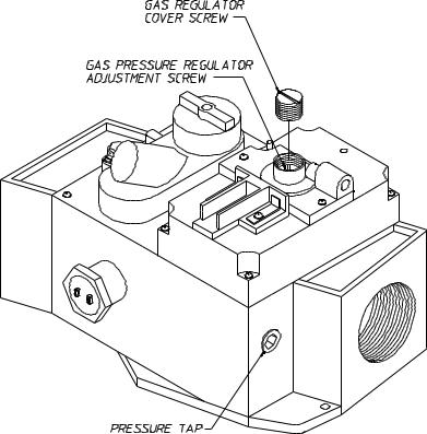
Once the flame has been established in both burner boxes, the natural gas outlet manifold pressure measured at each gas valve pressure tap must be 3-1/2 inches W.C. (water column) pressure. Connect a water tube manometer to the 1/8” F.P.T. gas pressure tap on the downstream side of each gas valve. There is a pressure regulator in both gas valves so the manifold pressure can be adjusted to 3-1/2” water column (W.C.). Unscrew the slotted regulator cover which is located on the top of each gas valve, and turn the regulator adjustment screw located underneath the cover (clockwise [CW] to increase manifold pressure and counterclockwise [CCW] to decrease manifold pressure).
MAN2633
The L.P. (liquid propane) gas pressure measured at each gas valve pressure tap must be 11-inches water column (W.C.) pressure, when the flame is established in both burner boxes. There is no means to adjust this pressure supplied with the dryer so the downstream L.P. pressure regulator must be adjusted to provide the 11inch water column (W.C.) outlet manifold pressure. Connect a water tube manometer to the 1/8” F.P.T. gas pressure tap on the downstream side of each gas valve to measure the manifold pressure.
IMPORTANT INFORMATION
Once the Blower Motor starts, both the FRONT AIR FLOW SWITCH and the REAR AIR FLOW SWITCH must pull in to indicate that there is sufficient air flow through the machine for safe ignition of both the Front Burner and the Rear Burner.
Refer to the system ladder diagram for “HEAT” signal information. There are several safety devices that must be satisfied prior to ignition. Any one of these safety devices can cause NO IGNITION, therefore a “HEAT FAULT”...i.e., FRONT AIR FLOW SWITCH
REAR AIR FLOW SWITCH EXHAUST HI-LIMIT SWITCH
FRONT BURNER INTAKE HI-LIMIT SWITCH
REAR BURNER INTAKE HI-LIMIT SWITCH
DEFECTIVE ELECTRICALHEAT CIRCUIT
1 2

ONE (1) BURNER WILL NOT IGNITE AT THE BEGINNING OF A CYCLE
This condition can be caused by the following:
•DEFECTIVE DSI (Direct Spark Ignition) MODULE
•DEFECTIVE SPARK IGNITOR/FLAME-PROBE ASSEMBLY
•DEFECTIVE GAS VALVE
•INSUFFICIENT GAS PRESSURE
•DEFECTIVE ELECTRICAL HEAT CIRCUIT
Refer to the ladder diagram and the schematics provided with this machine for reference to the above listed information.
ONE (1) BURNER WILL NOT IGNITE DURING A DRYING CYCLE
This condition can be caused by the following:
•DEFECTIVE DSI (Direct Spark Ignition) MODULE
•DEFECTIVE SPARK IGNITOR/FLAME-PROBE ASSEMBLY
•DEFECTIVE GAS VALVE
•DEFECTIVE ELECTRICAL HEAT CIRCUIT
•LOSS OF GAS PRESSURE
Refer to the ladder diagram and the schematics provided with this machine for reference to the above listed information.
CONTROL POWER (Indicator/Control Power On Push-Button)
This “GREEN LIGHTED” push-button is for enabling the 24 VAC control voltage to the control circuits of the machine. This push-button indicator must be “ON” for the system to load or dry material.
Refer to the ladder diagram included with the dryer for the function of this push-button in the 24 VAC control voltage latching control circuit.
CONTROL POWER (Off Push-Button)
This “RED NON-LIGHTED” push-button is for disabling the 24 VAC control voltage to the control circuits of the machine.
Refer to the ladder diagram included with the dryer for the function of this push-button in the 24 VAC control voltage latching control circuit.
SYSTEM LADDER DIAGRAM
The SYSTEM LADDER DIAGRAM is an overview on the electrical connections of the dryer. This diagram is for signal flow information and is a tool to direct an individual in the correct direction for troubleshooting this machine.
1 3
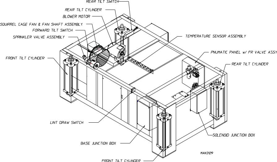
The dryer system is divided into a number of “electrical” sections which are as follows:
1.Right Front Control Panel
The RIGHT FRONT CONTROL PANEL is located in the Right Front Control Cabinet of the dryer. This panel is the heart of the drying system, where ALL control signals interface to or from this panel. The signals that interface to this panel are too many to list here, however, they are ALL identified on TB1 of its’ schematic diagram.
2.Right Base Electrical Enclosure
The RIGHT BASE ELECTRICAL ENCLOSURE is located towards the front of the right base section. An industrial multi-pin connector is used to connect the base section control signals to the tumbler section’s main control panel. This electrical enclosure is labeled CAUTION, HIGH VOLTAGE IS PRESENT IN THIS ENCLOSURE and incorporates the following electrical devices:
•The MAIN ELECTRICAL POWER to the machine
•The ELECTRICAL CONNECTION for the “OPTIONAL” SPRINKLER CIRCUIT POWER
•The THERMAL/MAGNETIC OVERLOAD and REVERSING CONTACTOR for the TUMBLER MOTOR
•The THERMAL/MAGNETIC OVERLOAD and REVERSING CONTACTOR for the BLOWER MOTOR
3.Right Base Interface Junction Box
The RIGHT BASE INTERFACE JUNCTION BOX is located towards the rear of the right base section and is used as a central location to interface the base section electrical components to the TILTING tumbler section. An industrial multi-pin connector is used to connect the base section control signals to the tumbler section’s main control panel. The control signals incorporated in the Right Base Interface Junction Box are:
SOLENOID CONTROL
•Front Up / Front Down
•Rear Up / Rear Down
•Open Front Door
•Supply Air Enable
•Air Jet
LINT DRAWER / GUARD STATUS
TUMBLER TEMPERATURE and HI-LIMIT INFORMATION TUMBLER LEVEL SENSE
•Front Level Switch
•Rear Level Switch
OPTIONAL SPRINKLER CONTROL SIGNALS
1 4

4.Optional Sprinkler Circuit
The OPTIONAL SPRINKLER CIRCUIT main control panel will be located in the left front electrical enclosure. If a SPRINKLER OPTION is included with the dryer, this panel will include an “AUTOMATIC EMERGENCY STOP” feature. This feature requires that the Sprinkler Circuit be functional for the dryer to be powered.
NOTE: There will be a dedicated electrical connection in the Right Electrical Junction Box for the Sprinkler Circuit.
1 5
SECTION I
SAFETY PRECAUTIONS
CAUTION: The dryer should never be left unattended while in operation.
WARNING: For your safety, the information in this manual must be followed to minimize the risk of fire or explosion or to prevent property damage, personal injury, or loss of life.
WARNING: The dryer must never be operated with any of the back guards, outer tops, or service panels removed. PERSONAL INJURY or FIRE COULD RESULT.
1.DO NOT store or use gasoline or other flammable vapors and liquids in the vicinity of this or any other appliance.
2.Purchaser/user should consult the local gas supplier for proper instructions to be followed in the event the user smells gas. The instructions should be posted in a prominent location.
3.WHAT TO DO IF YOU SMELL GAS...
a.DO NOT try to light any appliance.
b.DO NOT touch any electrical switch.
c.DO NOT use any phone in your building.
d.Clear the room, building, or area of ALL occupants.
e.IMMEDIATELY call your gas supplier from a neighbor's phone. Follow the gas supplier's instructions.
f.If you cannot reach your gas supplier, call the fire department.
4.Installation and service must be performed by a qualified installer, service agency, or gas supplier.
5.Dryer(s) must be exhausted to the outdoors.
6.Although ADC produces a very versatile machine, there are some articles that, due to fabric composition or cleaning method, should not be dried in it.
WARNING: Dry only water-washed fabrics. DO NOT dry articles spotted or washed in dry cleaning solvents, a combustible detergent, or "all purpose" cleaner.
EXPLOSION COULD RESULT.
WARNING: DO NOT dry rags or articles coated or contaminated with gasoline, kerosene, oil, paint, or wax.
EXPLOSION COULD RESULT.
1 6
WARNING: DO NOT dry mop heads. Contamination by wax or flammable solvent will create a fire hazard.
WARNING: DO NOT use heat for drying articles that contain plastic, foam, sponge rubber, or similarly textured rubberlike materials. Drying in a heated basket (tumbler) may damage plastics or rubber and also may be a fire hazard.
7.A program should be established for the inspection and cleaning of lint in the burner area, exhaust duct work, and area around the back of the dryer. The frequency of inspection and cleaning can best be determined from experience at each location.
WARNING: The collection of lint in the burner area and exhaust duct work can create a potential fire hazard.
8.For personal safety, the dryer must be electrically grounded in accordance with local codes and/or the NATIONAL ELECTRIC CODE ANSI/NFPA NO. 70-LATEST EDITION.
NOTE: Failure to do so will VOID THE WARRANTY.
9.UNDER NO CIRCUMSTANCES should the dryer door switches, lint drawer switch, or heat safety circuit, ever be disabled.
WARNING: PERSONAL INJURY or FIRE COULD RESULT.
10.This dryer is not to be used in the presence of dry cleaning solvents or fumes.
11.Remove articles from the dryer as soon as the drying cycle has been completed.
WARNING: Articles left in the dryer after the drying and cooling cycles have been completed can create a fire hazard.
12. READ and FOLLOW ALL CAUTION and DIRECTION LABELS ATTACHED TO THE DRYER.
IMPORTANT: Label ALL wires prior to disconnection when servicing the microprocessor controller (computer) and the ignition module. WIRING ERRORS CAN CAUSE
IMPROPER and DANGEROUS OPERATION.
IMPORTANT: YOU MUST DISCONNECT and LOCKOUT THE ELECTRIC SUPPLY and THE GAS SUPPLY or THE STEAM SUPPLY BEFOREANY COVERS or GUARDS ARE REMOVED FROM THE MACHINE TO ALLOW ACCESS FOR CLEANING, ADJUSTING, INSTALLATION, or TESTING OFANY EQUIPMENT per OSHA (Occupational Safety and Health Administration)
STANDARDS.
1 7

SECTION II
ROUTINE MAINTENANCE
A. CLEANING
A schedule should be established for periodic inspection, cleaning, and removal of lint from various areas of the dryer, as well as throughout the duct work system. The frequency of cleaning can best be determined from experience at each location. Maximum operating efficiency is dependent upon proper air circulation. The accumulation of lint can restrict this air flow. If the guidelines in this section are met, an ADC dryer will provide many years of efficient, trouble-free, and - most importantly - safe operation.
WARNING: LINT FROM MOST FABRICS IS HIGHLY COMBUSTIBLE. THE ACCUMULATION OF LINT CAN CREATE APOTENTIAL FIRE HAZARD.
WARNING: KEEP DRYER AREA CLEAR AND FREE FROM COMBUSTIBLE MATERIALS, GASOLINE, and OTHER FLAMMABLE VAPORS and LIQUIDS.
NOTE: REMOVE POWER FROM THE MACHINE BEFORE PERFORMING ANY MAINTENANCE IN THE MACHINE.
NOTE: Suggested time intervals shown are for average usage which is considered six (6) to eight (8) operational (running) hours per day.
SUGGESTED CLEANING SCHEDULE
EVERY THIRD or FOURTH LOAD
Clean the lint screen. A clogged lint screen will cause poor dryer performance. The lint screen is located in the lint drawer in the base of the dryer. Pull out the lint drawer, brush the lint off the lint screen, and remove the lint. Inspect the lint screen and replace if torn.
NOTE: The frequency of cleaning the lint screens can best be determined from experience at each location.
WEEKLY
Open the hinged panels on each side of the tumbler section and remove any lint accumulation from the tumbler drive motor, drive shafts, gear reducer, drive belts, drive wheels, and drive shaft bearings.
Slide the lint basket all the way out of the dryer and clean any lint accumulation off of the temperature sensor bracket, which is located above the lint basket.
WARNING: TO AVOID THE HAZARD OF ELECTRICAL SHOCK, DISCONTINUE ELECTRICALSUPPLYTO THE DRYER.
1 8

MONTHLY
Empty the compressed air filter bowl.
Clean any lint accumulation from the gas valve and burner area at the top of the dryer, the fan (impellor/ blower) motor, and the fan (impellor) bearings located in the dryer base.
EVERY 6 MONTHS
STEAM MODELS - clean the steam coil fins. We suggest using compressed air and a vacuum cleaner with brush attachment.
NOTE: When cleaning steam coil fins, be careful not to bend the fins. If fins are bent, straighten by using a fin comb, which is available from any local air conditioning supply house.
Inspect and remove any lint accumulation in customer furnished exhaust duct work system and from the dryers internal exhaust ducting.
NOTE: THE ACCUMULATION OF LINT IN THE EXHAUST DUCT WORK CAN CREATEAPOTENTIALFIRE HAZARD.
NOTE: DO NOT OBSTRUCT THE FLOW OF COMBUSTION and VENTILATION AIR. CHECK CUSTOMER FURNISHED BACK DRAFT DAMPERS IN THE EXHAUST DUCT WORK. INSPECT and REMOVE ANY LINT ACCUMULATION WHICH CAN CAUSE THE DAMPER TO BIND or STICK.
NOTE: When cleaning the dryer cabinet(s), avoid using harsh abrasives. A product intended for the cleaning of appliances is recommended.
Clean off any lint accumulation on top of the temperature probe and the hi-limit switch located above the lint basket.
1 9
B. LUBRICATION
MONTHLY
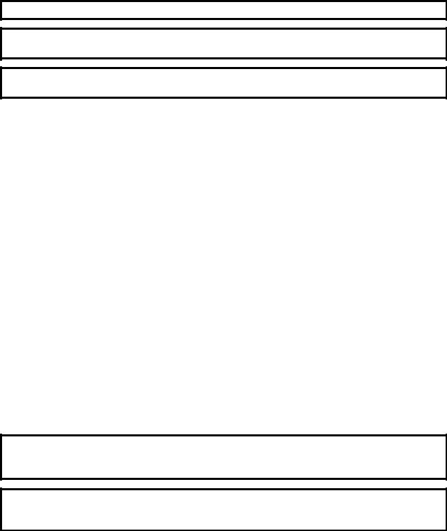
Check compressed air filter bowl for water. Empty by pressing the rubber petcock to the side. Additionally, check lubricator bowl for oil. If empty, remove the fill plug and add oil. (Use petroleum based 10/150 SSU misting oil.) Replace the fill plug.
NOTE: LUBRICATOR SHOULD BE SET AT 1 DROP PER CYCLE.
NOTE: REGULATOR PRESSURE IS TO BE SETAT 80 PSI.
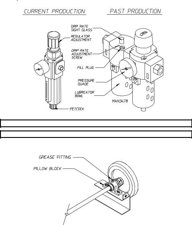
Apply high temperature grease to the four (4) 1-1/2" diameter tumbler drive shaft pillow block bearings and the two (2) 1-3/8" diameter blower shaft pillow block bearings. (Use Shell Alvania #3 grease or equivalent.)
MAN3203
Apply grease (use Shell Alvania #3 grease or equivalent) to the tilting hinges (on 1-Way Tilt Models Only).
2 0
EVERY 6 MONTHS
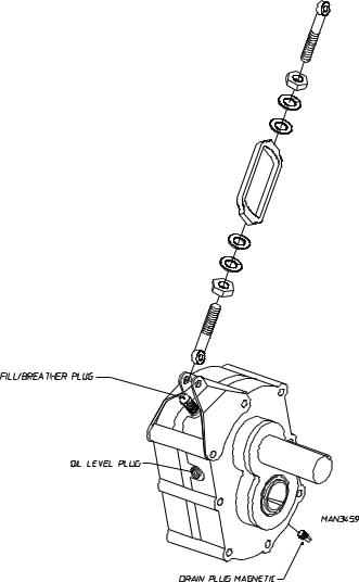
Change gear oil in the tumbler shaft gear reducer.
1.Remove the drain plug (located at the bottom rear of the reducer).
2.After oil is completely drained replace the drain plug.
3.Remove the vent plug and pour in 1.4 liters of Mobil Oil DTE HH5G (I.S.O. viscosity grade 460), SAE 90, or equivalent.
C. ADJUSTMENTS
7 DAYS AFTER INSTALLATION and EVERY 6 MONTHS THEREAFTER
Inspect bolts, nuts, screws, (bearing set screws), nonpermanent gas connections (i.e., unions, shut-off valves, orifices), and grounding connections. Fan (impellor) V-belts, along with the motor and drive belts should be examined and replaced if necessary. Tighten loose V-belts when necessary. Complete operational check of controls and valves. Complete operational check of ALL safety devices (i.e., door switches, lint drawer switch, sail switch, burner and hi-limit thermostats).
2 1

SECTION III
SPECIFICATIONS and DIMENSIONS
A. SPECIFICATIONS (Gas and Steam Models)
MAXIMUM CAPACITY (DRY WEIGHT) |
310 lbs. |
141 kg |
|||||
BASKET (TUMBLER) DIAMETER |
62-1/2" |
158.75 cm |
|||||
BASKET (TUMBLER) DEPTH |
|
60" |
152.4 cm |
||||
BASKET (TUMBLER) VOLUME |
106.5 cu. ft. |
3.02 cu.m. |
|||||
DRIVE MOTOR |
|
5 HP |
3.73 kw |
||||
BLOWER MOTOR (GAS/STEAM) |
15 HP/25 HP |
11.2 kw/18.7 kw |
|||||
DOOR OPENING |
|
36-3/4" WIDE x 43" HIGH |
93.3 cm x 109.2 cm |
||||
DOOR SILL HEIGHT - LEVEL |
36-1/2" |
92.71 cm |
|||||
COMPRESSED AIR |
|
80 PSI |
5.63 kg/cu.m. |
||||
COMPRESSED AIR CONNECTION |
1/8" F.P.T. |
.318 cm |
|||||
Gas* |
VOLTAGE AVAILABLE |
208-460v / 3ø / 3, 4w / 50/60 Hz |
|||||
HEAT INPUT |
|
1,125,000 btu/hr |
283,500 kcal/hr |
||||
APPROX. WEIGHT (UNCRATED) |
5,100 lbs. |
2,313 kg |
|||||
AIRFLOW |
|
6,500 cfm |
184 cmm |
||||
|
Inlet Pipe Size |
1-1/2" |
3.81 cm |
||||
|
VOLTAGE AVAILABLE |
208-460v / 3ø / 3, 4w / 50/60 Hz |
|||||
Steam* |
APPROX. WEIGHT (UNCRATED) |
5,600 lbs. |
2,540 kg |
||||
AIRFLOW |
|
8,500 cfm |
241 cmm |
||||
STEAM COMSUMPTION |
BOILER HP |
|
|
||||
NORMAL LOAD |
|
|
|||||
|
|
|
|
||||
|
|
|
|
|
|
|
|
1,153 lbs/hr |
524 kg/hr |
|
35 |
|
|
||
|
OPERATING STEAM PRESSURE |
STEAM SUPPLY |
STEAM RETURN |
||||
|
125 psi max |
8.79 kg/sq cm |
2" M.P.T. |
|
5.08 cm |
2" M.P.T. |
5.08 cm |
Shaded areas are stated in metric equivalents.
*Dryer must be provided with a clean, dry, regulated 80 PSI (+/- 10 psi) air supply (equivalent volume - 11 cfh [0.3 cmh]).
NOTE: ADC reserves the right to make changes in specifications at any time, without notice or obligation.
2 2
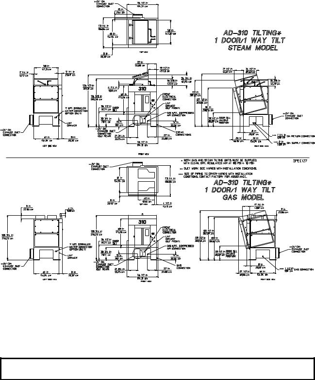
B. DIMENSIONS
NOTE: ADC reserves the right to make changes in specifications at any time, without notice or obligation.
2 3
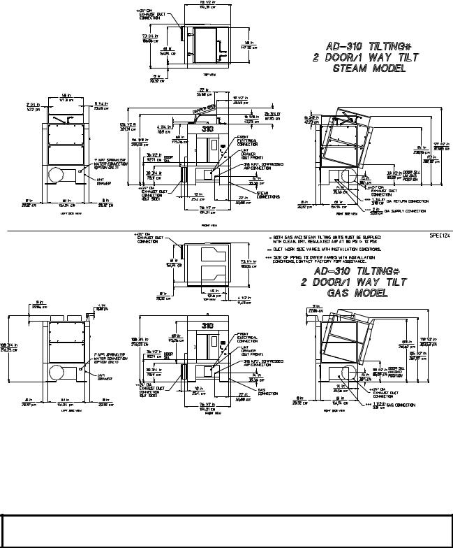
NOTE: ADC reserves the right to make changes in specifications at any time, without notice or
obligation.
2 4
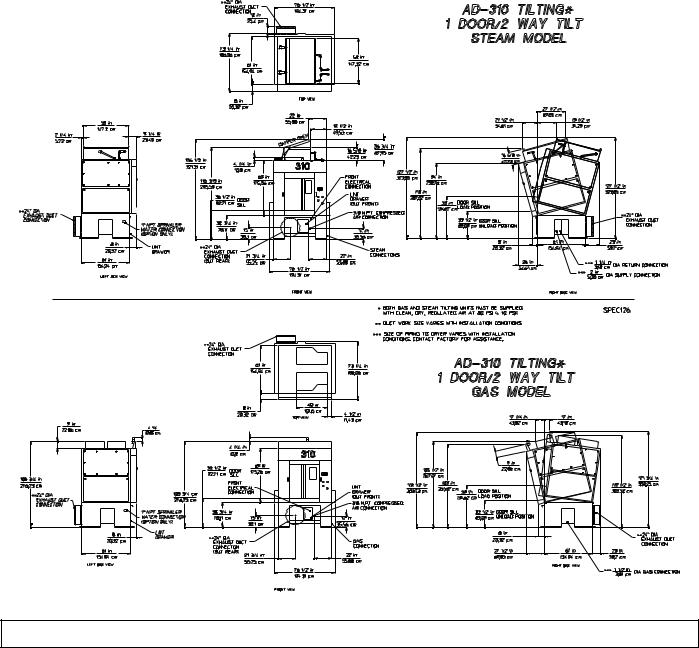
5 2
NOTE: ADC reserves the right to make changes in specifications at any time, without notice or obligation.
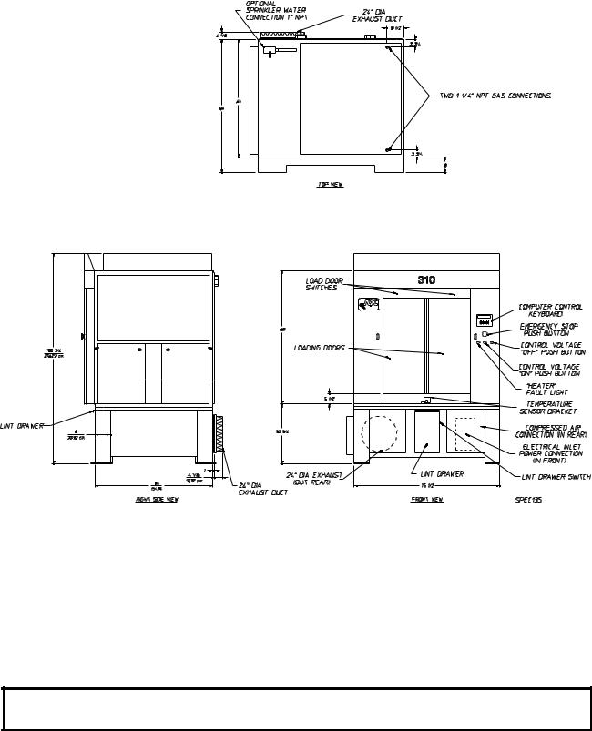
ADG-310 (Gas)
Non-Tilt
NOTE: ADC reserves the right to make changes in specifications at any time, without notice or obligation.
2 6
 Loading...