


 Loading...
Adam Equipment
CBD SERIES
(P.N. 6242, Revision A7, June 2007)
Software revision: 1.4-1.16
© Adam Equipment Company 2007

CONTENTS
1.0 |
INTRODUCTION....................................................................................................... |
2 |
|
2.0 |
TECHNICAL SPECIFICATIONS ............................................................................... |
3 |
|
2.1 |
SPECIFICATIONS FOR THE LOCAL SCALE....................................................... |
3 |
|
2.2 |
SPECIFICATIONS FOR THE REMOTE SCALE ................................................... |
3 |
|
2.3 |
COMMON SPECIFICATIONS ............................................................................... |
4 |
|
3.0 |
INSTALLATION......................................................................................................... |
5 |
|
3.1 |
LOCATING THE SCALES..................................................................................... |
5 |
|
3.2 |
SETTING UP THE SCALES.................................................................................. |
5 |
|
REMOTE SCALE SET UP ............................................................................................... |
7 |
||
4.0 |
KEY DESCRIPTIONS ............................................................................................... |
8 |
|
5.0 |
DISPLAYS ................................................................................................................ |
9 |
|
5.1 |
WEIGHT WINDOW ............................................................................................... |
9 |
|
5.2 |
UNIT WEIGHT WINDOW .................................................................................... |
10 |
|
5.3 |
COUNT WINDOW ............................................................................................... |
10 |
|
6.0 |
OPERATION........................................................................................................... |
11 |
|
6.1 |
ZEROING AND TARING THE DISPLAY............................................................. |
12 |
|
6.2 |
MEMORY FUNCTIONS ...................................................................................... |
14 |
|
6.2.1 Manual accumulation......................................................................................... |
14 |
||
6.2.2 |
Automatic accumulated total ........................................................................ |
14 |
|
6.3 |
PARTS COUNTING ............................................................................................ |
15 |
|
6.3.1 Weighing a sample to determine the Unit Weight......................................... |
15 |
||
6.3.2 Entering a known Unit Weight ...................................................................... |
16 |
||
6.3.3 Automatic update of unit weight ................................................................... |
16 |
||
6.3.4 Count pre-set or check-weighing.................................................................. |
17 |
||
6.4 |
PLU (Product Look Up) ...................................................................................... |
18 |
|
6.4.1 |
STORING PLU’S MANUALLY..................................................................... |
18 |
|
6.4.2 |
ENTERING DESCRIPTION MANUALLY ..................................................... |
20 |
|
6.4.3 |
RECALLING PLU’S MANUALLY.................................................................. |
21 |
|
7.0 |
PARAMETERS ....................................................................................................... |
22 |
|
7.1 |
USER PARAMETERS......................................................................................... |
22 |
|
8.0 |
BATTERY OPERATION ......................................................................................... |
24 |
|
9.0 |
RS-232 OUTPUT .................................................................................................... |
25 |
|
9.1 |
INPUT COMMANDS FORMAT ........................................................................... |
26 |
|
9.2 |
STORING DATA VIA RS232............................................................................... |
27 |
|
9.3 |
PLU ENTRY USING RS-232 INTERFACE.......................................................... |
27 |
|
10.0 |
CALIBRATION ........................................................................................................ |
28 |
|
11.0 |
ERROR CODES ..................................................................................................... |
29 |
|
12.0 |
TECHNICAL PARAMETERS .................................................................................. |
30 |
|
13.0 REPLACEMENT PARTS AND ACCESSORIES ..................................................... |
32 |
||
14.0 |
SERVICE INFORMATION ...................................................................................... |
32 |
|
© Adam Equipment Company 2007
1.0INTRODUCTION
•The CBD series offers a range of an accurate, fast and versatile counting scales that can use one additional external platform (Remote scale) for weighing or counting of heavier items.
•These counting scales have the ability to use many stored information (PLU).
•The scale can be operated using either pounds only, kilograms only or can be switched between pounds and kilograms.
•All have stainless steel weighing platform on a Steel base assembly.
•All the keypads are sealed, colour coded membrane switches and the displays are large easy to read liquid crystal type displays (LCD). The LCD’s are supplied with a backlight.
•All units include automatic zero tracking, audible alarm for pre-set weights, automatic tare, pre-set tare and an accumulation facility that allows the count to be stored and recalled as accumulated total.
•The scales have an expanded bi-directional RS-232 interface for communicating with a PC or printer.
© Adam Equipment Company 2007

2.0 TECHNICAL SPECIFICATIONS
2.1SPECIFICATIONS FOR THE LOCAL SCALE
Model # |
CBD 3 |
CBD 6 |
CBD 15 |
CBD 30 |
Maximum |
3 kg / |
6 kg / |
15 kg / |
30 kg / |
Capacity |
6 lb |
12 lb |
35 lb |
65 lb |
Readability |
0.0001 kg / |
0.0002 kg / |
0.0005 kg / |
0.001 kg / |
|
0.0002 lb |
0.0005 lb |
0.001 lb |
0.002 lb |
Tare Range |
-3 kg / |
-6 kg / |
-10 kg / |
-30 kg / |
|
-6 lb |
-12 lb |
-35 lb |
-65 lb |
Repeatability |
0.0001 kg / |
0.0002 kg / |
0.0005 kg / |
0.001 kg / |
(Std Dev) |
0.0002 lb |
0.0005 lb |
0.001 lb |
0.002 lb |
Linearity ± |
0.0002 kg / |
0.0004 kg / |
0.001 kg / |
0.002 kg / |
|
0.0005 lb |
0.001 lb |
0.002 lb |
0.004 lb |
Units of |
|
kg, lb |
|
|
Measure |
|
|
|
|
2.2SPECIFICATIONS FOR THE REMOTE SCALE
Excitation voltage |
5 VDC |
Signal range |
0-20 mV |
|
(allows 3 mV/ V LC with 5 mV zero offset) |
Zero range |
0-5 mV |
Sensitivity |
0.01 µV / internal ADC count or better |
Internal ADC counts |
500,000 maximum at 10 mV input |
Load |
87 ohm minimum, 4 X 350 ohm load cells |
Connection |
4 wire connection to load cells plus shield |
Maximum cable length |
6 meters |
Termination |
9 pin D-subminiature plug on scale |
© Adam Equipment Company 2007

2.3COMMON SPECIFICATIONS
Interface |
Bi-directional RS-232 Interface |
|
|
Stabilisation Time |
2 Seconds |
|
|
Operating Temperature |
0°C - 40°C |
|
|
Power supply |
9 VDC 800 mA from external power supply |
|
|
Calibration |
Automatic external |
|
|
Display |
3 x 6 digits LCD digital display |
|
|
Housing |
Indicator ABS Plastic, |
|
Stainless Steel platform |
|
|
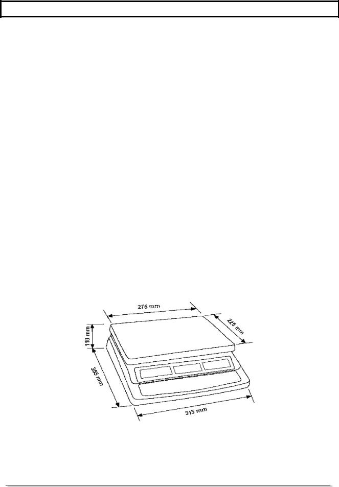
Pan size |
225 x 275 mm |
|
|
Overall dimensions |
315 x 355 x 110 mm |
|
|
Net weight |
4.1 kg |
|
|
Applications |
Counting Scale |
|
|
Functions |
Weighing, parts counting, accumulating memory, preset |
|
count with alarm, up to 100 PLUs with description, unit & |
|
tare weight |
|
|
Other Features and |
Accuracy enhancement for parts counting, internal |
Specs |
rechargeable battery (~70 hours operation) |
|
|
© Adam Equipment Company 2007
3.0INSTALLATION
3.1LOCATING THE SCALES
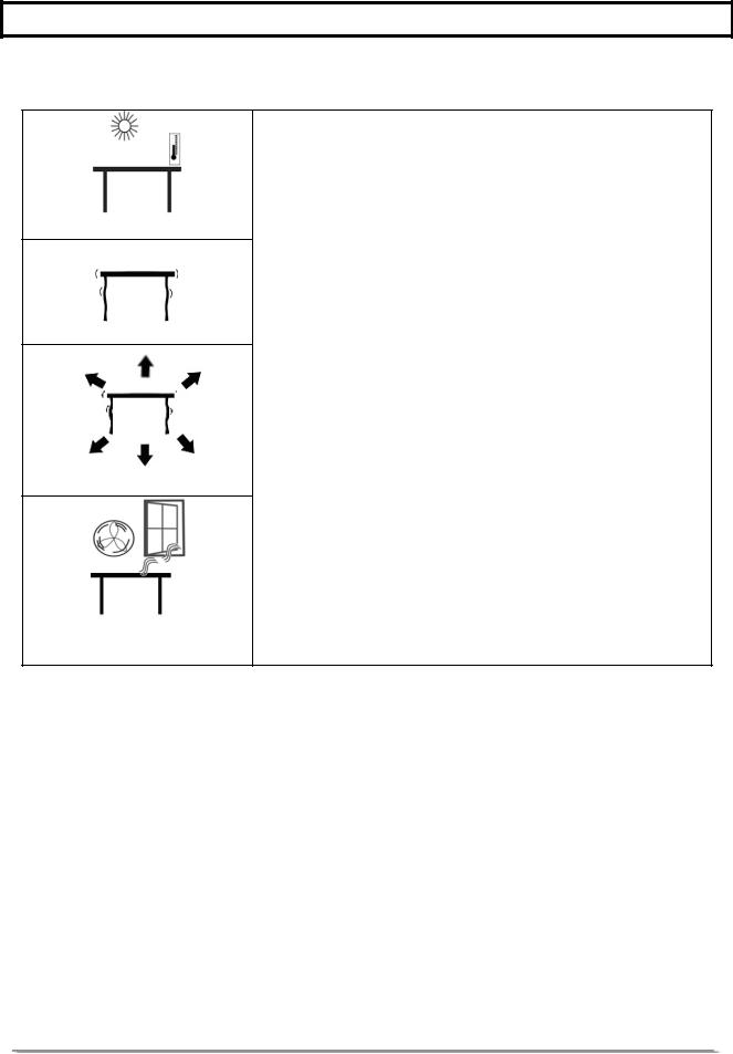
•The scales should not be placed in a location that will reduce the accuracy.
•Avoid extremes of temperature. Do not place in direct sunlight or near air conditioning vents.
•Avoid unsuitable tables. The table or floor must be rigid and not vibrate.
•Avoid unstable power sources. Do not use near large users of electricity such as welding equipment or large motors.
•Do not place near vibrating machinery.
•Avoid high humidity that might cause condensation. Avoid direct contact with water. Do not spray or immerse the scales in water.
•Avoid air movement such as from fans or opening doors. Do not place near open windows or air-conditioning vents.
•Keep the scales clean. Do not stack material on the scales when they are not in use.
3.2SETTING UP THE SCALES
SETTING UP THE LOCAL SCALE
•The CBD Series comes with a stainless steel platform packed separately.
•Place the platform in the locating holes on the top cover.
•Do not press with excessive force as this could damage the load cell inside.
•Level the scale by adjusting the four feet. The scale should be adjusted such that the bubble in the spirit level is in the centre of
©Adam Equipment Company 2007

the level and the scale is supported by all four feet.
•Attach the power supply cable to the connector on the right side of the scale base. Plug in the power supply module. The power switch is located at the right side of the scale base.
•The scale will show the model no in the “Weight” display window (CBD 15where 15 denotes the maximum capacity of the scale in Kg) and the current hardware and software revision numbers in the “Unit Weight” display window .
(For example “1.4-1 .07”: The first number “1.4” is the hardware revision number of the main circuit board and the next one “1 .07” is the software revision number).
•Next a self-test is followed. At the end of the self-test, it will display “0” in all three displays, if the zero condition has been achieved.
SETTING UP THE REMOTE SCALE
•The CBD Series can be connected to any size of load cell type weighing base via the Remote scale port on the right side of the scale case. Ensure you have the correct base for the scale as each is matched for calibration.
•Place the remote scale platform in the position where it is to be used. Level the scale by adjusting the four feet. If fitted with a spirit level then it should be adjusted such that the bubble is in the centre.
•Press [Local/Rem] and test weighing performance.
© Adam Equipment Company 2007

REMOTE SCALE CONNECTION
The cable for the load cell goes to a 9 pin D-subminiature plug connector with the following connections:
Pin numbers |
Connection |
Pins 1,2 |
- Excitation (0 V) |
Pins 4,5 |
+ Excitation (+5 V) |
Pin 7 |
+ Signal |
Pin 8 |
- Signal |
(The sense wires connections of a six wire load cell are not used but can be connected to the respective Excitation pins).
REMOTE SCALE SET UP
The remote scale should set for a realistic resolution with respect to the input provided by the load cell/s.
If a single 2 mV / V load cell is fitted and more than 60% of the load cell is used for full capacity then the high output of >6 mV span makes it possible to set a high resolution.
If this criterion is met then the remote scale can be set to a high resolution with a maximum of 1:30,000, i.e. 300 kg x 0.01 kg.
It will also be possible to sample on the remote scale with the same accuracy as the Local.
Where more than one load cell is fitted or the total load cell capacity is not utilised then a reduced resolution should be selected in the remote scale technical set up. For example, if a system uses four 2 mV / V 1000 kg load cells for a scale of 1000 kg capacity then the span output at full scale will be only 2.5 mV.
In this situation the resolution should be reduced to give a good number of ADC counts per displayed division. ie. Set to 1:5000 or 1000 kg x 0.2 kg.
Setting a high resolution without providing a good input to the remote scale ADC will not give better accuracy and may make the scale difficult to meet performance specification.
For best performance ensure a minimum of 0.1 µV / d.
© Adam Equipment Company 2007

4.0 KEY DESCRIPTIONS
[0-9, •]
These keys are used to manually enter a value for tare weights, unit weight and sample size. A secondary function is to enter alpha-numeric characters for PLU descriptions etc.
[CE]
Pressing this key clears the unit weight or an erroneous entry. It also clears the memory accumulation when the total is displayed.
[M+]
This key is used to add the current count to the accumulator. It also recalls the memory when pressed with no load on the scale. Up to 99 values or full capacity of the weight display can be added. Also prints the displayed values when Auto print is switched off.
[Smpl]
This is used to enter the number of items of a sample.
[PLU]
To store and recall the Product Look Up sample information.
[U. Wt./Units]
This key is used to enter the weight of a sample manually. It will also change the weighing units when other units are enabled.
[PST]
To set the upper limit for the number of items counted. When this upper limit is exceeded the scale will sound the beeper. A secondary function is to use it for the backlight control setting.
[Print]
It is used to print the weighing data.
[Local Rem]
© Adam Equipment Company 2007
This key is used to select the local or remote scale.
[Tare/Zero]
This key has a combined Zero and Tare function.
If the net weight is below ±2% of maximum then it acts as a Zero key. This sets the zero point for all subsequent weighing by setting the display to zero. It also tares the scale by storing the current weight in the memory as a tare value, subtracting the tare value from the total weight and displaying the results as a net weight.
5.0 DISPLAYS
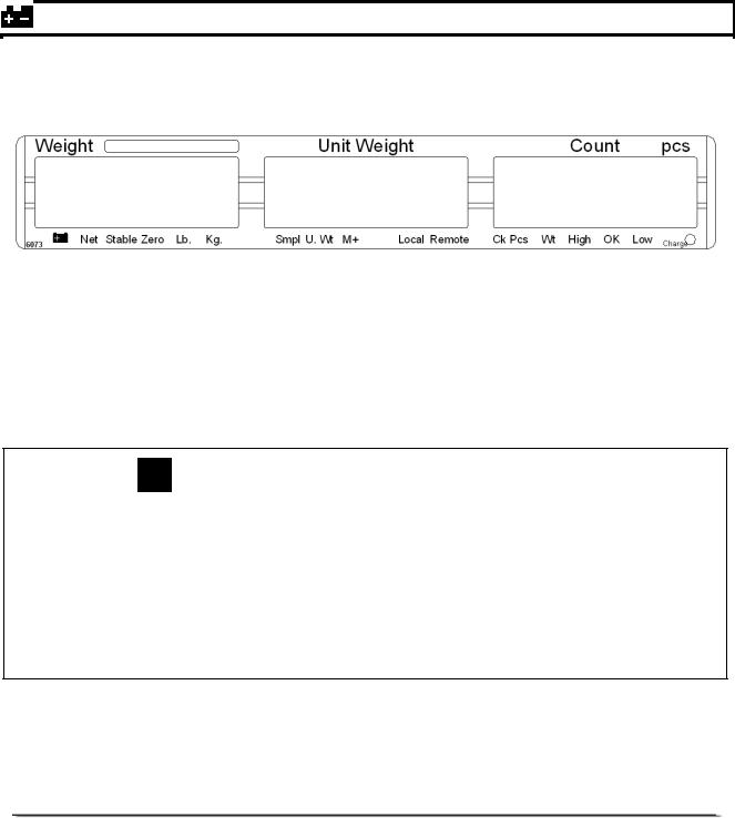
The scales have three display windows- Weight, Unit Weight and Count.
5.1WEIGHT WINDOW
This consists of a 6 digit display to indicate the weight on the scale.
An arrow above the symbols will indicate the following:
Low battery,
Net Weight Display, "Net"
Stability indicator, “Stable”
Zero indicator, “Zero”
Unit in use indicator, “Lb” or “Kg”
© Adam Equipment Company 2007
5.2UNIT WEIGHT WINDOW
•This display will show the unit weight of a sample. This value is either entered by the user manually or computed by the scale. The unit of measure is either gram on all scales with kilogram selected as weighing unit or in pounds.
•When the scale has determined that there is insufficient number of samples to accurately determine the count, an arrow will be shown above "Smpl".
•When the unit weight is not large enough to determine an accurate count, the arrow will show at "U.Wt".
•When a value has been entered into the memory, the arrow above "M+" will be on.
•In both the cases the scale continues to operate and the indicators are to alert the user of a potential problem.
5.3COUNT WINDOW
•This display will show the number of items on the scale or the value of the accumulated count. See the OPERATION section.
• An arrow above the symbols will indicate the following:
Checkweighing is active during counting, "Ck Pcs"
Checkweighing is active during weighing, “Ck Wt”
Checkweighing is active, result is above the High Limit, “High”
Checkweighing is active, result is between the Low and High
Limit, “OK”
Checkweighing is active, result is below the Low Limit, “Low”
•Just under the “Count” display is an LED to indicate the status of the battery charging. When the scale is plugged into the main power the internal battery will be charged. If the LED is green, the battery has a full charge. If it is red, the battery requires further charging and yellow indicates the battery is being charged.
©Adam Equipment Company 2007
Loading...