


GFK
© Adam Equipment Company 2011
Adam Equipment
GBK and GFK Series
(
P.N. 9679, Revision C1, February 2011)
Software Rev.
V1.17 GK-H scales for Europe
V2.25 EC Approved scale
V3.32 GK scale for Europe
V4.07 GK-H scale for USA
V5.32 GK scales for USA
© Adam Equipment Company 2011
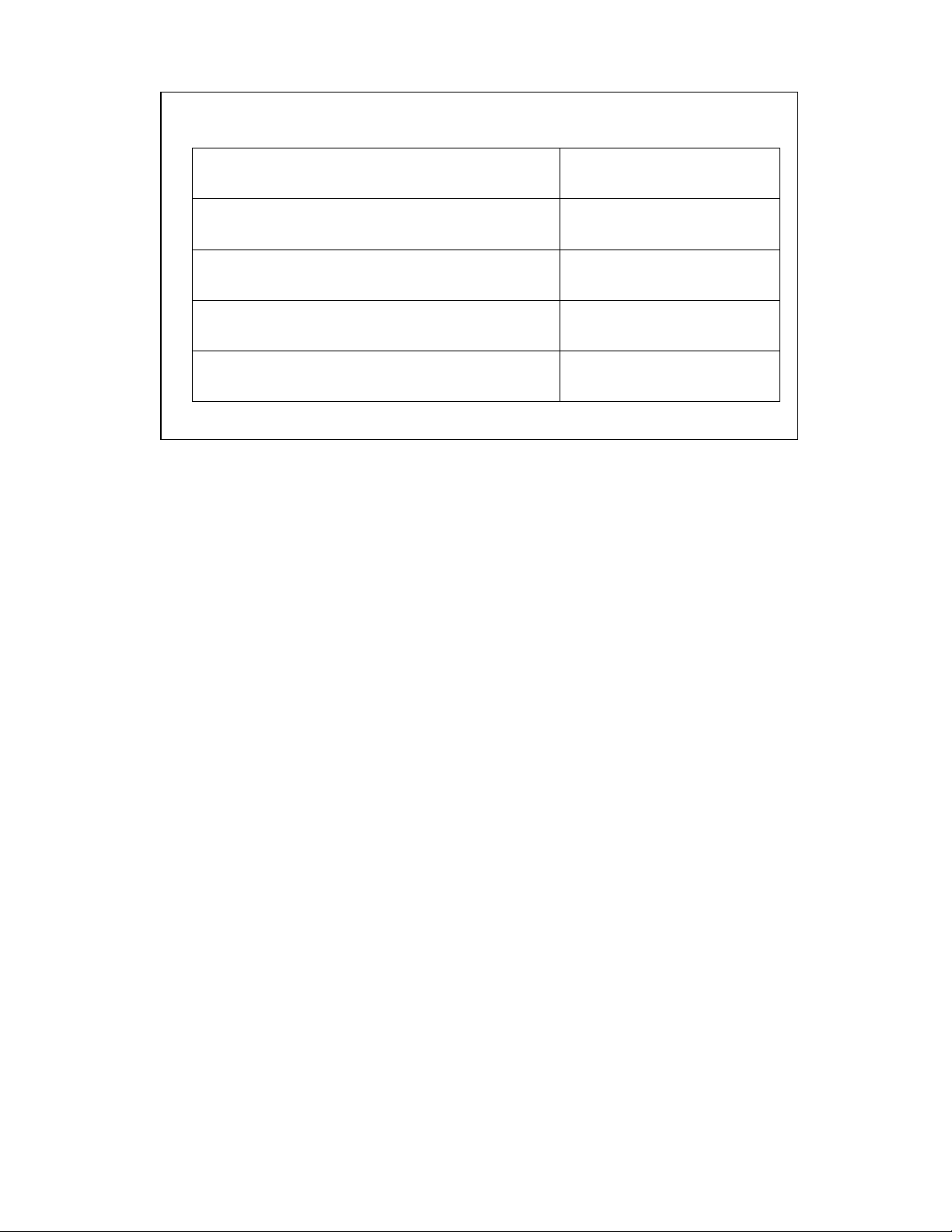
Easy Reference:
Model name of the scale:
Serial number of the unit:
Software revision number
(Displayed when power is first turned on):
Date of Purchase:
Name of the supplier and place:

1 | page
© Adam Equipment Company 2011
CONTENTS
1.
INTRODUCTION..................................................................................... 3
2.
SPECIFICATIONS .................................................................................. 4
3.
INSTALLATION...................................................................................... 9
3.1. UNPACKING.........................................................................................................9
3.2. LOCATING............................................................................................................9
3.3 SETTING UP THE SCALES ...............................................................................10
4.
KEYPAD ............................................................................................... 11
5.
DISPLAY............................................................................................... 13
5.1. SYMBOLS AND INDICATORS...........................................................................13
6.
CALIBRATION COUNTER FOR APPROVED SCALES...................... 14
7.
BATTERY ............................................................................................. 16
8.
BACKLIGHT ......................................................................................... 16
9.
AUTO POWER OFF.............................................................................. 16
10.
OPERATION...................................................................................... 17
10.1. ZEROING.........................................................................................................17
10.2. TARING...........................................................................................................17
10.2.1 MANUAL TARE...........................................................................................17
10.2.2 PRESET TARE (NOT AVAILABLE ON APPROVED SCALES).................18
10.3. WEIGHING ......................................................................................................19
10.4. PARTS COUNTING.........................................................................................19
10.5. CHECK-WEIGHING ........................................................................................22
10.5.1 SETTING UP WHILE WEIGHING................................................................23
10.5.2 SETTING UP WHILE PARTS COUNTING OR % WEIGHING ....................24
10.6. LIMITS STORING AND RECALLING .............................................................24
10.7. PERCENT WEIGHING ....................................................................................26
10.8. ANIMAL (DYNAMIC) WEIGHING ...................................................................29
10.8.1 ANIMAL WEIGHING PROCEDURE............................................................30
10.9. ACCUMULATED TOTAL................................................................................31
10.9.1 MANUAL ACCUMULATION........................................................................31
10.9.2 AUTOMATIC ACCUMULATION..................................................................33
11.
RS-232 SPECIFICATION................................................................... 34
11.1. INPUT COMMANDS FORMAT .......................................................................39
12.
CALIBRATION................................................................................... 40
13.
PARAMETER SETTINGS.................................................................. 41
13.1. CHECK WEIGHING PARAMETERS...............................................................41
13.2. RS-232 PARAMETERS...................................................................................44
13.3. SCALE PARAMETERS...................................................................................46
13.4. PERCENT WEIGHING AND ANIMAL WEIGHING .........................................48
14.
ERROR MESSAGES ......................................................................... 49
15.
SERVICE PARAMETERS.................................................................. 51
15.1. ACCESS TO PARAMETERS..........................................................................51
15.2. USING “1000” TO ENTER THE SERVICE PARAMETERS ...........................52
16.
REPLACEMENT PARTS AND ACCESSORIES................................ 57
17.
SERVICE INFORMATION.................................................................. 58
18.
WARRANTY INFORMATION............................................................. 59
19.
APPENDIX......................................................................................... 60

2 | page
© Adam Equipment Company 2011

3 | page
© Adam Equipment Company 2011
1. INTRODUCTION
• The GBK/GFK scales provides an accurate, fast and versatile general
purpose weighing scales with parts counting, percent weighing and
check-weighing functions.
• The GBK/GFK has LEDs to indicate when a weight is below the low limit,
between the limits or above the high limit next to the display. These
can work in conjunction with an audible alarm for check weighing as
well as LCD showing LO, OK and HI.
• The GBK/GFK is supplied with a RS-232 bi-directional interface and real
time clock (RTC).
• The GBK/GFK has a sealed keypad with colour coded membrane
switches and a large easy to read liquid crystal type display (LCD)
supplied with a backlight.
• Includes automatic zero tracking, semi-automatic tare and
accumulation facility that allows the weight to be stored and recalled as
an accumulated total.
• OIML Approved models, GBK/GFK-M, do not allow pounds units, have
calibration controlled by jumpers or passcodes and other limitations as
noted in the manual.
4
| P a g e © Adam Equipment Company 2011
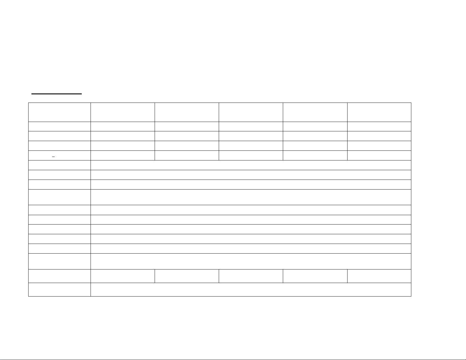
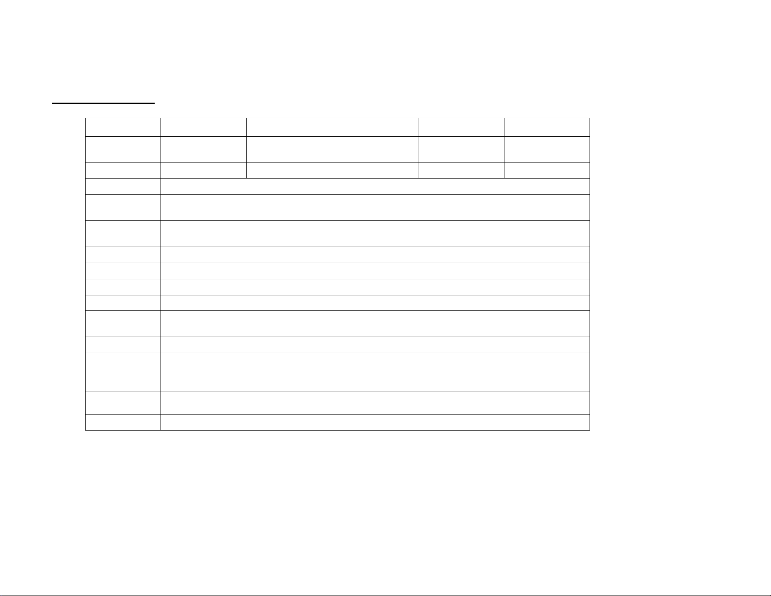
2. SPECIFICATIONS
GBK Models
Model #
GBK 8 /
GBK 16a
GBK 16/
GBK 35a
GBK 32 /
GBK 70a
GBK 60 /
GBK 130a
GBK 120 /
GBK 260a
Maximum Capacity 8kg/16lb 16kg/35lb 32kg/70lb 60kg/130lb 120kg/260lb
Readability 0.1g/0.0002lb 0.5g/0.001lb 1g/0.002lb 2g/0.005lb 5g/0.01lb
Repeatability (Std Dev) 0.2g/0.0004lb 1g/0.002lb 2g/0.004lb 4g/0.01lb 10g/0.02lb
Linearity + 0.3g/0.0006lb 1g/0.002lb 2g/0.004lb 4g/0.01lb
10g/0.02lb
Units of Measure Grams & Kilograms, XXXa also to have Pounds, Ounces, & Pound/Ounces
Stabilization Time 2-3 Secs
Operating Temperature -10°C to +40°C / +14°F to +104°F
Power Supply 230VAC 50/60Hz. in Europe, Asia and South Africa.
12vDC 800mA UL/CSA adapter for USA
Calibration External
Calibration Mass User Selectable
Display Backlit Green display 25mm with capacity tracker
Balance Housing Cast aluminum base, Pantone cool grey painted base, stainless steel grade 304 Top pan, ABS Cool grey indicator housing
Pan Size
300mm x 400mm / 11.8” x 15.5”
Overal Dimensions
(w x d x h)
300mm x 620mm x 860mm / 11.8” x 24.4” x 33.8”
Net Weight 7.6kg / 16.8 Lb 7.6kg / 16.8 Lb 7.6kg / 16.8 Lb 7.6kg / 16.8 Lb 7.6kg / 16.8 Lb
Features Weighing/Counting/Checkweighing with LED lights/Percentage/Hold function/RS232
5
| P a g e © Adam Equipment Company 2011
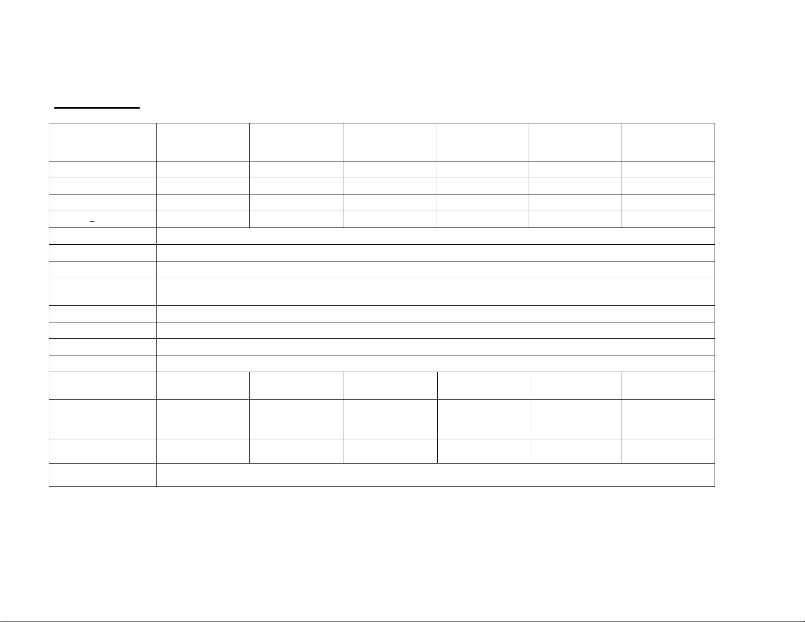
GFK Models
Model #
GFK 75 /
GFK 165a
GFK 150 /
GFK 330a
GFK 300 /
GFK 660a
GFK 600 /
GFK 1320a
GFK 75H /
GFK165aH
GFK 150H /
GFK330aH
Maximum Capacity
75kg / 165lb 150kg / 330lb 300kg / 660lb 600kg / 1320lb 75kg / 165lb 150kg / 330lb
Readability
5g / 0.01lb 10g / 0.02lb 20g / 0.05lb 50g / 0.1lb 1g / 0.002lb 2g / 0.005lb
Repeatability (Std Dev)
5g / 0.01lb 10g / 0.02lb 20g / 0.05lb 50g / 0.1lb 2g / 0.004lb 4g / 0.01lb
Linearity +
10g / 0.02lb 20g / 0.04lb 40g / 0.1lb 100g / 0.2lb 3g / 0.006lb 6g / 0.015lb
Units of Measure Grams & Kilograms, XXXa also to have Pounds, Ounces, & Pound/Ounces
Stabilization Time 2-3 Secs
Operating Temperature -10°C to +40°C / +14°F to +104°F
Power Supply 230VAC 50/60Hz. in Europe, Asia and South Africa.
12vDC 800mA UL/CSA adapter for USA
Calibration External
Calibration Mass User Selectable
Display Backlit Green display 25mm with capacity tracker
Balance Housing Cast aluminum base, Pantone cool grey painted base, stainless steel grade 304 Top pan, ABS Cool grey indicator housing
Pan Size 400mm x 500mm
15.7” x 19.7”
400mm x 500mm
15.7” x 19.7”
400mm x 500mm
15.7” x 19.7”
600mm x 800mm
23.6” x 31.5”
400mm x 500mm
15.7” x 19.7”
400mm x 500mm
15.7” x 19.7”
Overal Dimensions
(w x d x h)
400 mm x 620 mm x
860 mm
15.7” x 24.4” x 33.8”
400 mm x 620 mm x
860 mm
15.7” x 24.4” x 33.8”
400 mm x 620 mm x
860 mm
15.7” x 24.4” x 33.8”
600 mm x 940 mm x
900 mm
23.6” x 37” x 35.4”
400 mm x 620 mm x
860 mm
15.7” x 24.4” x 33.8”
400 mm x 620 mm x
860 mm
15.7” x 24.4” x 33.8”
Net Weight 12.5kg / 27.6 Lb 12.5kg / 27.6 Lb 12.5kg / 27.6 Lb 25.5 kg / 56.2 Lb 12.5kg / 27.6 Lb 12.5kg / 27.6 Lb
Features Weighing/Counting/Checkweighing with LED lights/Percentage/Hold function/RS232
6
| P a g e © Adam Equipment Company 2011
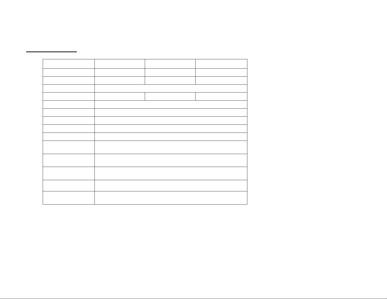
GBK-M Models
Model #
GBK 6M GBK 15M GBK 30M GBK 60M GBK 150M
Maximum
Capacity
6kg 15kg 30kg 60kg 150kg
Readability 0.002kg 0.005kg 0.01kg 0.02kg 0.05kg
Units of Measure Kilograms only
Stabilization
Time
2-3 Secs
Operating
Temperature
-10°C to +40°C / +14°F to +104°F
Power Supply
230VAC 50/60Hz.
Calibration
External
Calibration Mass
User Selectable
Display
Backlit Green display 25mm with capacity tracker
Balance Housing
Cast Aluminum base, Pantone cool grey painted base, stainless steel grade 304 Top pan, ABS Cool grey indicator
housing
Pan Size 300mm x 400mm / 11.8” x 15.7”
Overal
Dimensions
(w x d x h)
300mm x 620mm x 860mm / 11.8” x 24.4” x 33.8”
Net Weight
7.6kg / 16.8 Lb
Features
Weighing/Counting/Checkweighing with LED lights/Percentage/Hold function/RS232
7
| P a g e © Adam Equipment Company 2011
GFK-M Models
Model #
GFK 60M GFK 150M GFK 300M
Maximum Capacity 60kg 150kg 300kg
Readability 0.02kg 0.05kg 0.1kg
Units of Measure Kilograms only
Stabilization Time 2-3 Secs 2-3 Secs 2-3 Secs
Operating Temperature
-10°C to +40°C / +14°F to +104°F
Power Supply
230VAC 50/60Hz.
Calibration
External
Calibration Mass
User Selectable
Display
Backlit Green display 25mm with capacity tracker
Balance Housing
Cast Aluminum base, Pantone cool grey painted base, stainless steel grade 304
Top pan, ABS Cool grey indicator housing
Pan Size
400 mm x 500 mm
15.7” x 19.7”
Overal Dimensions
(w x d x h)
400 mm x 620 mm x 860 mm
15.7” x 24.4” x 33.8”
Net Weight
13kg / 28 Lb
Features
Weighing/Counting/Checkweighing with LED lights/Percentage/Hold
function/RS232

8
| P a g e © Adam Equipment Company 2011
9
| P a g e © Adam Equipment Company 2011
3. INSTALLATION
3.1. UNPACKING
The GBK/GFK scales have already been adjusted to work with a platform and have
been configured for this application. The platform and indicator have been
calibrated as a pair and must be used together .
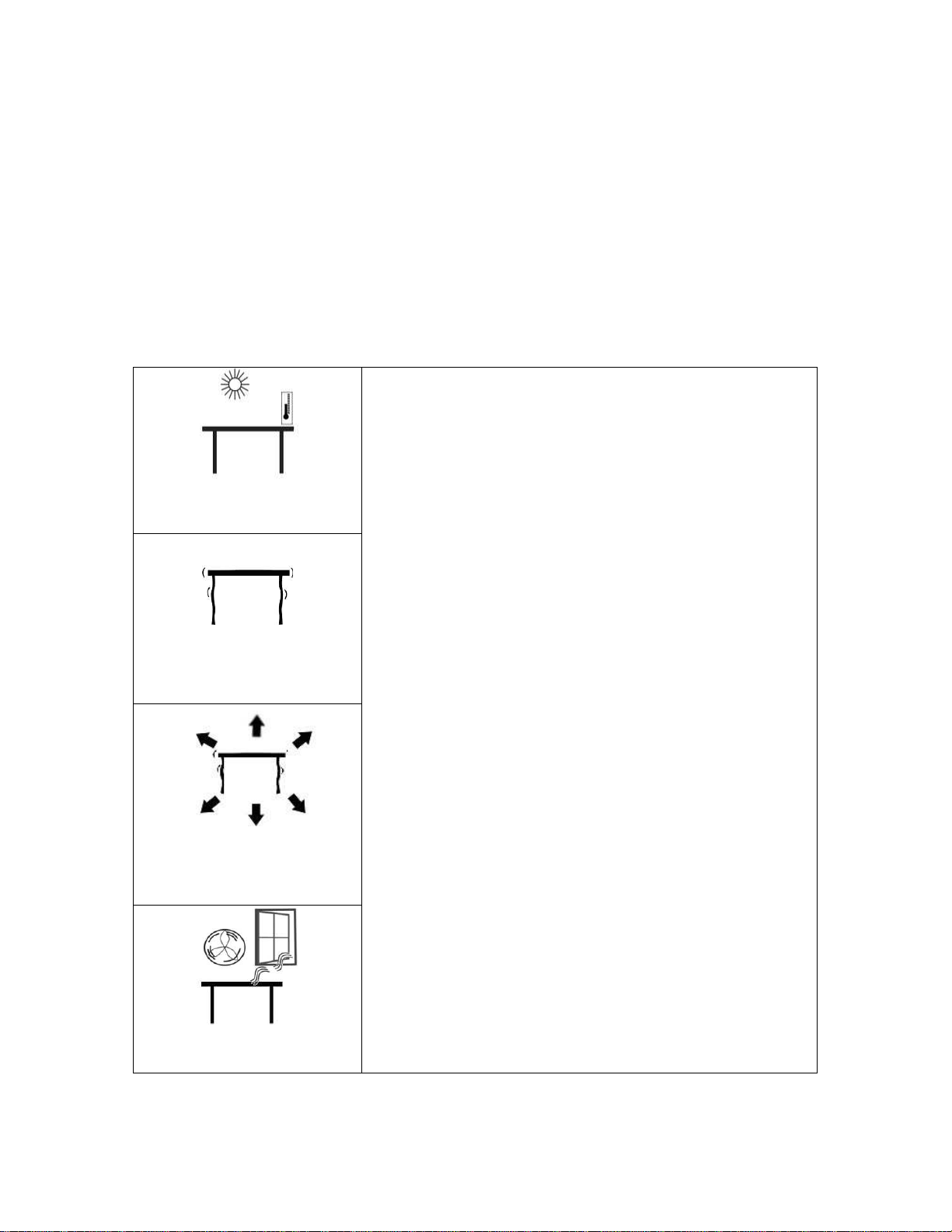
3.2. LOCATING
• The scales should not be placed in a location that will
reduce the accuracy.
• Avoid extremes of temperature. Do not place in direct
sunlight or near air conditioning vents.
• Avoid unsuitable tables. The table or floor must be rigid
and not vibrate.
• Avoid unstable power sources. Do not use near large
users of electricity such as welding equipment or large
motors.
• Do not place near vibrating machinery.
• Avoid high humidity that might cause condensation.
Avoid direct contact with water. Do not spray or
immerse the scales in water.
• Avoid air movement such as from fans or opening doors.
Do not place near open windows or air-conditioning
vents.
•
Keep the scales clean. Do not stack material on the
scales when they are not in use.

10
| P a g e © Adam Equipment Company 2011
3.3 SETTING UP THE SCALES
• The pillar is attached to the base using a bracket that must be attached
to the base frame first using the 4 bolts supplied. The pillar is secured
to the bracket using 2 sets of screws. The cable from the base to the
indicator module is run through the tube and taken out through the
plastic support at the top. Excess cable can be stored within the tube.
• The GBK/GFK Series comes with a stainless steel platform packed
separately. Place the platform in the base.
• Level the scale by adjusting the four feet. If the scale rocks re-adjust the
feet.
• Attach the indicator module to the pillar by sliding it over the bracket
with the flanges engaged in the groves on the base. Attach the cable
from the base to the connector on the rear of the indicator.
• Attach the power to the indicator. Press the [On/Off] key. The software
revision number will be displayed followed by a self-test showing all
digits before the zero is displayed along with the unit of weight that was
selected last.
• If the scale is an approved version, GBK/GFK..M, and the Calibration
Counter has been enabled (see section 6) the current values will be
displayed. These values should match the values marked on the scale
at the time of verification, if it has been verified.
11
| P a g e © Adam Equipment Company 2011
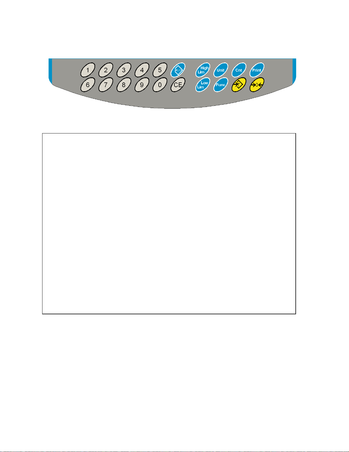
4. KEYPAD
KEYS PRIMARY FUNCTION SECONDARY FUNCTION
[Zero] Sets the zero point for all subsequent
weighing. The display shows zero.
Escape from any setting menus
[Tare] It tares the scale and stores the current
weight in memory as a tare value, subtracts
the tare value from the weight and shows
the results. This is the net weight.
Accept the set values
[Unit] This is used to select the weighing units
from a preset list of available units.
Allows the weight, unit weight, and
count to be seen when parts
counting or to change from weight
to % in percent weighing

12
| P a g e © Adam Equipment Company 2011
[Low
Limit]
&
[High
Limit]
It sets the limits for check weighing and
allows setting of either the low limit or the
high limit or both.
None
[
Lim] It stores and recalls any of 10 preset limits
None
[Func] This is used to select percent weighing, RS-
232 parameters, Operation of the bar
graph, RTC settings, User ID and Scale ID.
None
[Count]
Enter Parts Counting
None.
[Print] It is used to print the results to a PC or
printer using the RS-232 interface. It also
adds the value to the accumulation memory
if the accumulation function is not
automatic.
None
[1] to [0]
and [CE]
Allow entering numerical values where
required, setting of limits, tare value, time
and date for example.
13
| P a g e © Adam Equipment Company 2011
5. DISPLAY
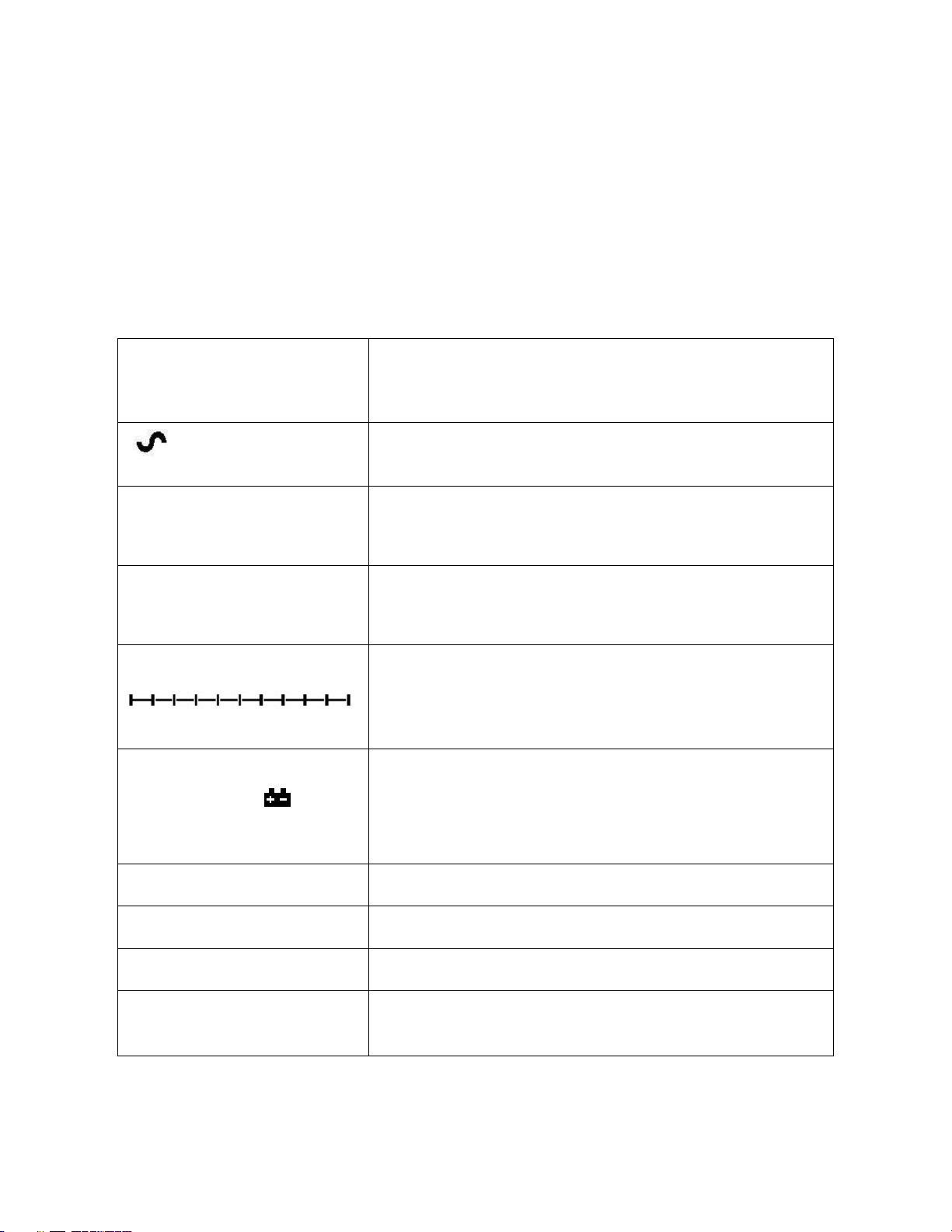
5.1. SYMBOLS AND INDICATORS
The LCD has unique symbols to indicate the following:
0
The display is at Zero
The scale is Stable
Net
Net weight- The scale has been tared
kg / lb
Symbols shown for the units
Capacity Tracker- A bar graph indicating the proportion of the
scale capacity being used by the weight on the platform
bAt LO or
Low battery
%
The scale is in Percent weighing mode
pcs
The scale is in Parts counting mode
HI, OK, LO
The scale is in Check weighing mode
:
The colons “:” are used to separate pounds from ounces and
for the real time clock.
14
| P a g e © Adam Equipment Company 2011
Next to the LCD are a number of LED’s that show when the weight is below, within
or over the limits during check weighing.
Weight LED LCD
below the low limit Amber LO
Within the limits Green OK
Above the high limit Red HI
NOTE: The LED’s can be set by the user to off, bar, spot or segment mode. See “F3
LED” in section 13.1
The LED can be set to display as a bar, increasing from Low to OK to High, a single
spot increasing from Low, OK to High, or as a single bar that changes colour as the
weight progresses from Low to OK to High.
6. CALIBRATION COUNTER FOR APPROVED SCALES
The approved (GBK/GFK-M Model) scales have the ability to control access to the
calibration or metrology parameters using a passcode to limit access. The
requirements for doing this stipulate the code should be apparent and recorded in a
suitable location on the scale.
In this way if the record of the Calibration or Parameter counters do not agree with
recorded settings the responsible person inspecting the scale can take appropriate
action.

15
| P a g e © Adam Equipment Company 2011
The Counters are incremented any time the calibration section or the Factory
parameters section have been modified.
At power on, the display will show the current software revision number followed
by the message of the Calibration Count “[AL[nt” then a number i.e. “123”. The
number from the counter memory. Then the Parameter Counter message of
“PAr[nt” and probably a different number, i.e. “234”. The counters cannot be
reset to 0, they will increment until the display can no longer hold the values. (1 to
999999). It is expected we will never have more than 1 million calibrations in the
life of the machine.
Each display is held for 1-2 seconds.
The scale will then continue to do the display test and go to normal weighing.
If during the time the counting displays are shown, the user presses the [Tare] key,
the user will be given a message to enter the passcode necessary to calibrate the
scale, “P - - - - “ Enter the code “P0000” to Enter calibration or “P1000” to enter
the parameters, followed by pressing the [Tare] key.
The Calibration access will allow user calibration (See section 15.1) and the
parameter code will allow access to the following parameters. (see section 15.2).
“F4 Int” Initial Zero Range
“F5 rEZ” Re-Zero range
“F6 SCS” Successive Tare Enable
“F7 Cnt” Display ADC counts
“F8 Zem” Zero Mode
“F9 Lvd” Low voltage detection

16
| P a g e © Adam Equipment Company 2011
7. BATTERY
• The scales can be operated from the rechargeable battery, if desired.
The GBK/GFK scales have up to 70 hours battery life before needing to
be recharged if the backlight is disabled and the battery is fully charged.
• When the battery needs charging a symbol on the display will turn on.
The battery should be charged when the symbol is on. The scale will still
operate for a period of time after which it will automatically switch off
to protect the battery.
• To charge the battery, simply plug into the mains power supply. The
scale does not need to be turned on.
• The battery should be charged for 12 hours for full capacity.
• To the right of the display is a LED to indicate the status of battery
charging. When the scale is plugged into the mains power the internal
battery will be charged. If the LED is green the battery is being charged.
If it is red it is nearly discharged and yellow indicates the battery is
increasing the charge level. Continue to charge overnight for a
complete re-charge.
8. BACKLIGHT
The backlight for the LCD can be set by the user to always off, always on or
automatic (on only when the scale is in use or a key is pressed). See setting of the
parameter “S2 bL” in section 13.3.
9. AUTO POWER OFF
The auto power off can be set by the user to disable the feature or to a pre-set time
interval. See setting of the parameter “S3 AoF “ in section 13.3.
17
| P a g e © Adam Equipment Company 2011
10. OPERATION
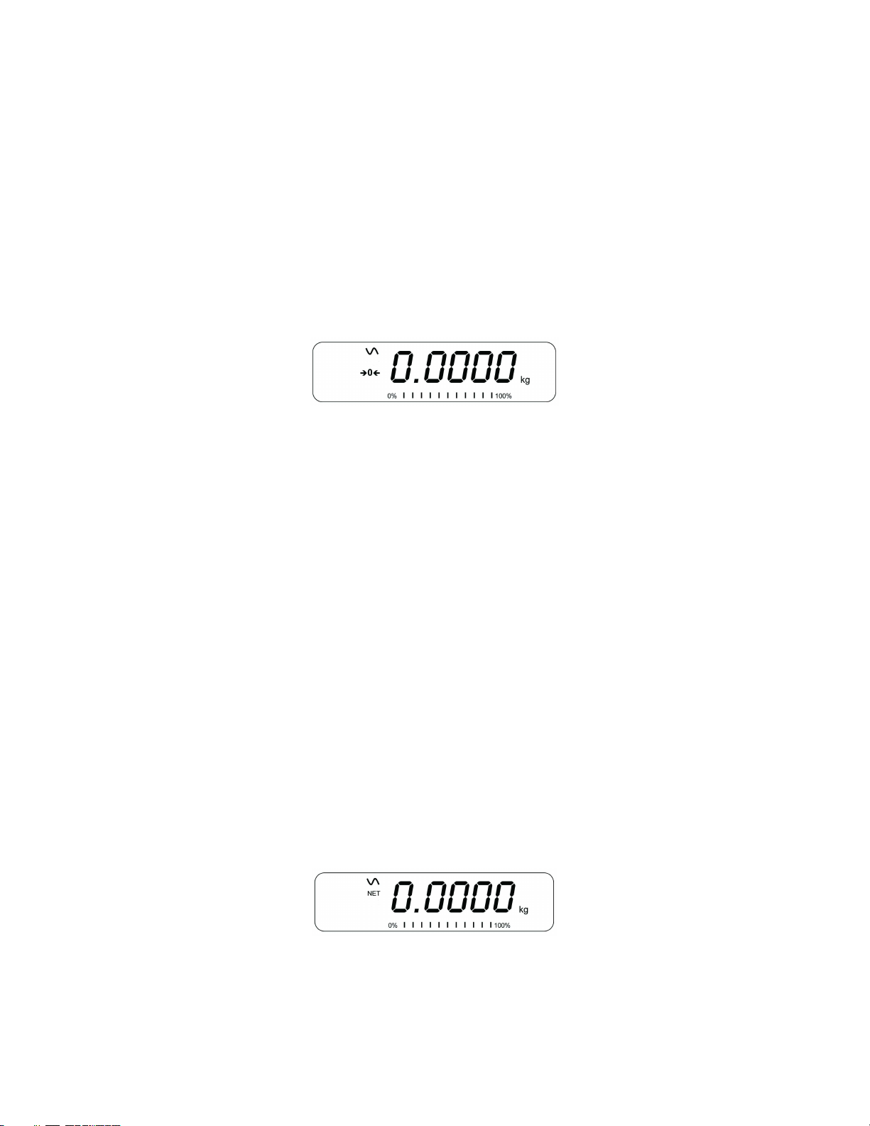
10.1. ZEROING
• You can press the [Zero] key at any time to set the zero point from
which all other weighing and counting is measured. This will usually be
necessary when the platform is empty. When the zero point is obtained
the display will show the zero indicator.
• The scale has an automatic re-zeroing function to account for minor
drifting or accumulation of material on the platform. However you may
need to press [Zero] to re-zero the scale if small amount of weight is
still shown when the platform is empty.
10.2. TARING
10.2.1 MANUAL TARE
• Zero the scale by pressing [Zero]. The zero indicator will be on. Place a
container on the platform and its weight will be displayed.
• Press [Tare] when the reading is stable. The weight that was displayed
is stored as the tare value and it is subtracted from the display, leaving
zero on the display. The stable and Net indicator will be on.
• As a product is added only the weight of the product will be shown. The
scale could be tared a second time if another type of product was to be
18
| P a g e © Adam Equipment Company 2011
added to the first one. Again only the weight that is added after taring
will be displayed.
NOTE:
When the container is removed a negative value will be shown. If the scale was
tared just before removing the container, this value is the gross weight of the
container plus all products which were removed. The zero indicator will also be on
as the platform is back to the same condition it was when [Zero] was pressed last.
Press [Tare] or [Zero] to remove the tare value and display zero. The Net indicator
will disappear.
10.2.2 PRESET TARE (NOT AVAILABLE ON APPROVED SCALES)
When the scale is at zero with no weight on the platform it is possible to enter a
preset tare.
• Zero the scale by pressing [Zero]. The zero indicator will be on.
• Enter a value using the numeric keys.
• Press [Tare] to tare the scale. The value that was entered is stored as
the tare value and it is subtracted from the display, leaving a negative
number on the display.
19
| P a g e © Adam Equipment Company 2011
10.3. WEIGHING
To determine the weight of a sample, first tare an empty container if used,
then place the sample in the container. The display will show the weight and
the unit of weight currently in use.
To change the weighing unit press the [Unit] key. The only alternative
weighing unit is pounds. This can be enabled by the user in the parameters
section. See section 13.3.
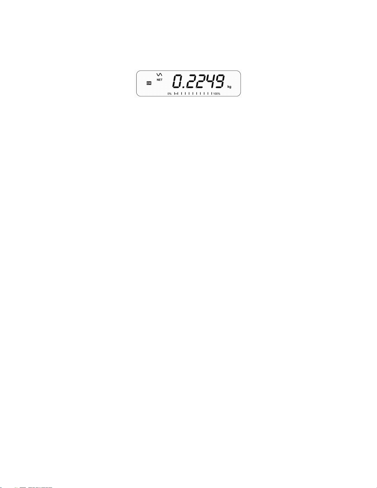
10.4. PARTS COUNTING
The scale can be used to count parts based on the average weight of a sample
weighed. When more parts are added the total number of parts are displayed.
• If a container is to be used, place this container on the platform before
entering parts counting and press [Tare].
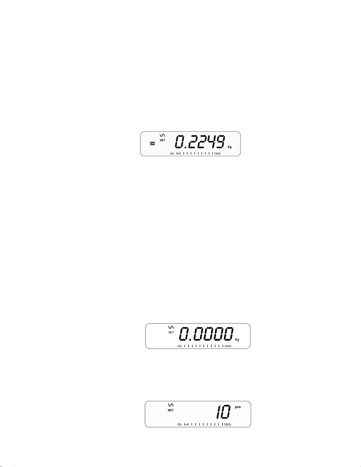
• Press [Cnt] to enter the Parts Counting mode. The display will show the
last sample size used. For example, “10 Pcs”.
 Loading...