


 Loading...
Aspire M3600/M5600
AcerPower M461/S461
Service Guide
Service guide files and updates are available on the AIPG/CSD web; for more information, please refer to http://csd.acer.com.tw
PRINTED IN TAIWAN

Revision History
Please refer to the table below for the updates made on Aspire M3600/M5600 and AcerPower M461/S461 service guide.
Date |
Chapter |
Updates |
|
|
|
|
|
|
|
|
|
4

Copyright
Copyright © 2006 by Acer Incorporated. All rights reserved. No part of this publication may be reproduced, transmitted, transcribed, stored in a retrieval system, or translated into any language or computer language, in any form or by any means, electronic, mechanical, magnetic, optical, chemical, manual or otherwise, without the prior written permission of Acer Incorporated.
Disclaimer
The information in this guide is subject to change without notice.
Acer Incorporated makes no representations or warranties, either expressed or implied, with respect to the contents hereof and specifically disclaims any warranties of merchantability or fitness for any particular purpose. Any Acer Incorporated software described in this manual is sold or licensed "as is". Should the programs prove defective following their purchase, the buyer (and not Acer Incorporated, its distributor, or its dealer) assumes the entire cost of all necessary servicing, repair, and any incidental or consequential damages resulting from any defect in the software.
Acer is a registered trademark of Acer Corporation. Intel is a registered trademark of Intel Corporation.
Pentium 4 and Celeron are trademarks of Intel Corporation.
Other brand and product names are trademarks and/or registered trademarks of their respective holders.
5

Conventions
The following conventions are used in this manual:
SCREEN |
Denotes actual messages that appear |
MESSAGES |
on screen. |
|
|
NOTE |
Gives bits and pieces of additional |
|
information related to the current |
|
topic. |
|
|
WARNING |
Alerts you to any damage that might |
|
result from doing or not doing specific |
|
actions. |
|
|
CAUTION |
Gives precautionary measures to |
|
avoid possible hardware or software |
|
problems. |
|
|
IMPORTANT |
Reminds you to do specific actions |
|
relevant to the accomplishment of |
|
procedures. |
|
|
6

Preface
Before using this information and the product it supports, please read the following general information.
1.This Service Guide provides you with all technical information relating to the BASIC CONFIGURATION decided for Acer's "global" product offering. To better fit local market requirements and enhance product competitiveness, your regional office MAY have decided to extend the functionality of a machine (e.g. add-on card, modem, or extra memory capability). These LOCALIZED FEATURES will NOT be covered in this generic service guide. In such cases, please contact your regional offices or the responsible personnel/channel to provide you with further technical details.
2.Please note WHEN ORDERING FRU PARTS, that you should check the most up-to-date information available on your regional web or channel. If, for whatever reason, a part number change is made, it will not be noted in the printed Service Guide. For ACER-AUTHORIZED SERVICE PROVIDERS, your Acer office may have a DIFFERENT part number code to those given in the FRU list of this printed Service Guide. You MUST use the list provided by your regional Acer office to order FRU parts for repair and service of customer machines.
7

8

Chapter 1 System Specifications 1
Features 1
Mainboard Placement 4 Block Diagram 6
Aspire M3600/M5600 Front Panel 7
Aspire M3600/M5600 Rear Panel 9 AcerPower M461 Front Panel 10 AcerPower M461 Rear Panel 11 System Peripherals 12
Acer eRecovery 14
Acer disc-to-disc recovery 16
Hardware Specifications and Configurations 17
Power Management Function (ACPI support function) 22
Chapter 2System Utilities 23
About the Setup Utility 23
Product Information 25
Standard CMOS Features 26
Advanced BIOS Features 28
Advanced Chipset Features 31
Integrated Peripherals 33
Power Management Setup 36
PnP/PCI Configurations 38
PC Health Status 39
Frequency Control 40
Chapter 3 Machine Disassembly and Replacement 42
General Information 43
Disassembly Procedure 44
Chapter 4Troubleshooting 57
Chapter 5 Jumper and Connector Information 58
Main Board Placement 58
Jumper Setting 60
Chapter 6 FRU (Field Replaceable Unit) List 67
Exploded Diagram 68
FRU List 69
1

2

Chapter 1
System Specifications
Features
Processor
Socket Type : Intel Socket T LGA 775 pin
Processor Type : Intel Conroe FSB 800/1066 MHz
Chipset
Intel 946GZ+ICH7DH
PCB
Form Factor : Mirco ATX
Size (Max.) : 244mm x 244mm
Memory
Memory Type : DDRII 1.8V unbuffered SDRAM module support
No. of Channel (Dual/Signal) : Dual channel should be enabled always when plug-in 2 same memory size DDRII memory module
Socket Type : un-buffered 240 pin DIMM socket DIMM Slot : 2
Graphics
Onboard graphic solution: Intel 946GZ(Intel GMA X3000) integrated graphics device solution Dual View function support(by Intel ADD2/ADD2+)
One D-sub VGA port on rear
PCI
One PCI Express x16 slot
One PCI Express x1 slot
Two PCI 2.3 Slots
FDD
Slot Quantity : 1
Support 1.44MB 3.5” Devices
SATA
4 pin SATA IDE connector Transfer rate support:
1.5GB/s and 3.0 GB/s
Storage type support : HDD/CD-ROM/DVD-ROM/DVD-RW/DVD+RW/DVD Dual/DVD SuperMultiPlus
Chapter 1 |
1 |

Audio
Audio Type : HD Codec
Audio Channel : 7.1 channel
Audio Controller /Codec : Realtek ALC888
Support SPDIF out
Audio Connectors/Headers:
Rear 6 jack follow HD audio definition
Microphone In
Headphone Out
S/PDIF out header
Support front panel audio header
Add HD de-pop CKT
AUX-In
LAN
Type : Intel 82573L (Vidalia) PCI-E Giga LAN
Supports 10/100/1000MB Ethernet environment
IEEE 1394
IEEE 1394 Controller : TI TSB43AB23PDTG4
IEEE 1394 Port : One rear 6pin IEEE 1394 port
One header on board
USB
Controller : Intel ICH7DH USB Type : 2.0/1.1 Connectors Quantity: 8
Real Panel : 4
Onboard header: 2 ports for front daughter board, 2 ports for card reader+IR Standard Intel FPIO pin definition
BIOS
BIOS Type : Phoenix-Award BIOS 4MB Flash BIOS
Award PnP BIOS compatible with SM BIOS 2.3 ACPI, SMBIOS 2.3, Green and Boot Block.
Provides DMI 2.0, WFM 2.0, WOL, and SM Bus for system management.
2 |
Chapter 1 |
I/O Connector
Controller : Super I/O ITE 8718
Rear I/O Connector
1 PS/2 Keyboard Port, 1 PS/2 Mouse Port
1 Parallel Port, 1 Serial Port
1 D-sub VGA Port
1 LAN Port
4 USB Ports
7.1 channel phone jack
1 6 pin 1394 port
Onboard Connector
1 CPU socket
2 Memory slots
1 PCI Express x16 slot
1 PCI Express x1 slot
2 PCI slots
1 FDD connector
1 IDE slot
4 SATA2 IDE connectors
3 2*5 pin Intel FPIO sepcification USB pin connectors.
1 2*5 pin Intel FPIO spec. microphone in/headphone out connector 1 2*5 pin serial port connector
1 CD-IN 4pin connector (CD-ROM Audio Input) 1 S/PDIF out 4pin jumper
1 4pin CPU Fan connector
1 3pin system fan connector with 3pin system fan co-lay 1 24pin ATX interface PS3/PS2 SPS connector
1 2*7 pin front panel IO header one 2pin OBR header
1 onboard buzzer
1 1394 header
Color management for on board connecter
Power Supply
PSP Type : 250W
Chapter 1 |
3 |

Mainboard Placement
No. |
Name |
Description |
|
|
|
1 |
CPU Socket |
LGA775 socket for Intel CoreTM2 Duo/Pentium D/Pentium |
|
|
4/Celeron D CPUs |
|
|
|
2 |
CPU_FAN1 |
CPU cooling fan connector |
|
|
|
3 |
DIMM1~2 |
DDR2 240 pin SDRAM slots |
|
|
|
4 |
FDD1 |
Floppy diskette drive connector |
|
|
|
5 |
ATX1 |
Standard 24pin ATX power connector |
|
|
|
6 |
IDE1 |
Primary IDE channel |
|
|
|
7 |
BIOS_WP |
BIOS flash protect jumper |
|
|
|
8 |
SATA1~4 |
Serial ATA connectors |
|
|
|
9 |
JP2 |
Jumper |
|
|
|
10 |
JP1 |
Jumper |
|
|
|
11 |
PANEL1 |
Front panel switch/LED header |
|
|
|
12 |
CLR_CMOS1 |
Clear CMOS jumper |
|
|
|
13 |
USB3~4 |
Front panel USB headers |
|
|
|
14 |
1394A1 |
Onboard 1394a header |
|
|
|
15 |
COM2 |
Onboard Serial port header |
|
|
|
16 |
SPDIF |
SPDIF out header |
|
|
|
17 |
AUDIO2 |
Front Panel Audio header |
|
|
|
4 |
Chapter 1 |

No. |
Name |
Description |
|
|
|
18 |
CD_IN1 |
Analog audio input connector |
|
|
|
19 |
PCI1~2 |
32 bit add-on card slot |
|
|
|
20 |
PCIEX1 |
PCI Express x1 slot |
|
|
|
21 |
PCIEX16 |
PCI Express x16 slot |
|
|
|
22 |
SYS_FAN1 |
System fan connector |
|
|
|
23 |
R_USB |
Front Panel USB header |
|
|
|
24 |
ATX12V1 |
Auxiliary 4pin power connector |
|
|
|
Chapter 1 |
5 |
Block Diagram
DEVICE |
IDSEL |
INT# |
REQ# |
GNT# |
|
|
PCI1 |
17 |
C/D/E/F |
PREQ-0 |
PGNT-0 |
|
INTEL |
|
|
|
|
|
|
|
PCI2 |
18 |
D/E/F/G |
PREQ-1 |
PGNT-1 |
|
P4 Processor |
|
|
|
|
|
|
|
1394 |
19 |
E |
PREQ-2 |
PGNT-2 |
|
PSC, Tejas - |
|
|
|
|
|
|
|
|
|
|
|
|
||
|
|
|
|
|
|
LGA 775 pin |
|
|
|
|
|
|
|
|
|
|
|
|
|
|
Analong Display
RAMDAC: 400MHz
Resolutions Up To 2048x1536@75Hz
BW : 4.1GB/s @ FSB : 533MHz & Freq : 133MHz
BW : 6.4GB/s @ FSB : 800MHz & Freq : 200MHz
|
|
|
|
INTEL |
|
VGA (G only) |
|
946GZ |
|
|
|
|
|
|
|
|
|
|
FC-BGA |
|
PCIEx16 |
|
|
|
|
|
|
|
|
BW : 10.7GB/s @ DDR2 :533/667MHz
DDIMM1: DDR Socket 184P
DDIMM2 : DDR Socket 184P
|
|
|
|
|
|
|
|
|
|
|
|
|
|
|
|
USB V2.0 |
|
|
USB1 |
|
|
USB2 |
|
USB3 |
|
|
USB4 |
|
|
USBLAN |
|
|
|
||
|
2 ports |
|
|
2 ports |
|
2 ports |
|
|
2 ports |
|
|
8 ports |
|
|
|
||
|
|
|
|
|
|
|
|
|
|
|
|
|
|
Up to Ultra ATA/100 |
|||
|
|
|
|
|
|
|
|
|
IDE1 40pin |
|
Two IDE Channel |
||||||
Mic In |
|
|
|
Audio Codec |
|
|
AC' 97 & Lan I/F |
||||||||||
Line Out |
|
|
|
|
|
||||||||||||
|
|
|
|
ALC888 |
|
|
|
|
|
|
|
|
|
||||
Line In |
|
|
|
|
|
|
|
|
|
|
|
|
|
||||
|
|
|
|
|
|
|
|
|
|
|
|
|
|
|
|
||
CEN/BAS |
|
|
|
|
|
|
|
|
|
|
|
|
intel |
|
|||
|
|
|
|
|
|
|
|
|
|
|
|
FWH |
|
||||
SURRON |
|
|
|
|
|
|
|
|
|
|
|
|
|
||||
|
|
|
SATA1 7Pin |
|
|
|
|
|
|
32pin PLCC |
|
||||||
SID SURRON |
|
|
|
SATA2 7pin |
|
|
|
|
|
|
|
|
|
|
|||
|
|
|
|
|
|
|
|
|
|
|
|
|
|||||
|
|
|
|
|
SATA3 7Pin |
BW : 150MB/s |
|
|
|
|
|
||||||
|
|
|
|
|
SATA4 7pin |
|
|
|
|
|
|
|
|
|
|
||
|
BW : 2GB/s (Support Lsoch) |
|
|
|
|
|
|
|
|
||||
|
|
|
|
|
|
PCIEX1 |
|
|
|
|
|
|
|
|
|
|
|
|
|
|
|
|
|
|
|
|
|
INTEL |
|
|
|
|
PCIEx1 LAN |
|
|
|
USBLAN |
||||
|
|
|
|
|
|
|
RJ45 |
||||||
ICH7DH |
|
BW : 133MB/s @Freq : 33MHz |
82573L |
|
|
|
|||||||
|
|
|
|
|
|
|
|||||||
|
|
|
|
|
|
|
|
|
|||||
609pin EBGA |
|
|
|
|
|
|
|
|
|
||||
|
|
|
|
PCI1 Slot 120pin @ AD17 |
|
|
|||||||
|
|
|
|
|
|
|
|||||||
|
|
|
|
|
|
|
|
|
|
|
|||
|
|
|
|
|
|
|
PCI2 Slot 120pin @ AD18 |
|
|||||
LPC bus |
|
|
|
|
|
|
|
|
|
|
|
||
|
|
|
|
|
|
|
|
|
|
|
|||
|
|
|
|
|
|
|
|
|
|
|
|
|
|
|
|
|
|
VIA |
|
|
|
|
|
|
|
|
|
|
|
|
|
6307/8 |
|
|
|
|
|
|
|
|
|
|
ITE 8718 |
|
|
|
|
|
|
|
|
|
|
|
|
|
Super I/O |
|
|
|
|
|
|
|
|
|
|
|
|
|
128pin PQFP |
|
|
|
|
|
|
|
|
|
|
|
|
|
|
|
|
|
|
|
|
|
|
|
|
|
|
PCB : 244 x 244 mm ; 4 layers
of
6 |
Chapter 1 |
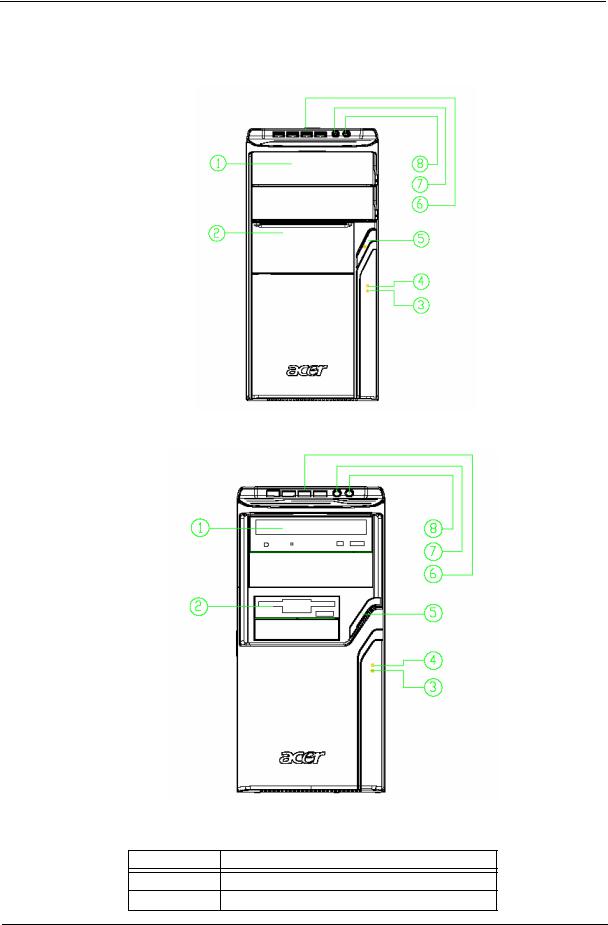
Aspire M3600/M5600 Front Panel
The computer’s front panel consists of the following:
Label |
Description |
1Optical drive
2Slide door/ Floppy disk drive
Chapter 1 |
7 |

Label |
Description |
|
|
3 |
LAN LED |
4 |
HDD LED |
|
|
5 |
Power Button |
|
|
6 |
USB ports |
|
|
7 |
MIC phone |
|
|
8 |
Speaker out |
|
|
8 |
Chapter 1 |
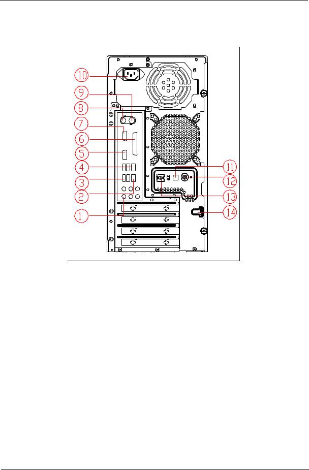
Aspire M3600/M5600 Rear Panel
No. |
Description |
No. |
Description |
|
|
|
|
1 |
6 audio jacks |
2 |
LAN port |
|
|
|
|
3 |
USB ports |
4 |
1394 port |
|
|
|
|
5 |
CRT/LCD port |
6 |
Parallel port |
|
|
|
|
7 |
HDMI port |
8 |
PS/2 keyboard connector |
|
|
|
|
9 |
PS/2 mouse connector |
10 |
Power cord port |
|
|
|
|
11 |
SPDIF bracket |
12 |
SPDIF port |
|
|
|
|
13 |
Recovery switch holder |
14 |
Lock handle |
|
|
|
|
Chapter 1 |
9 |
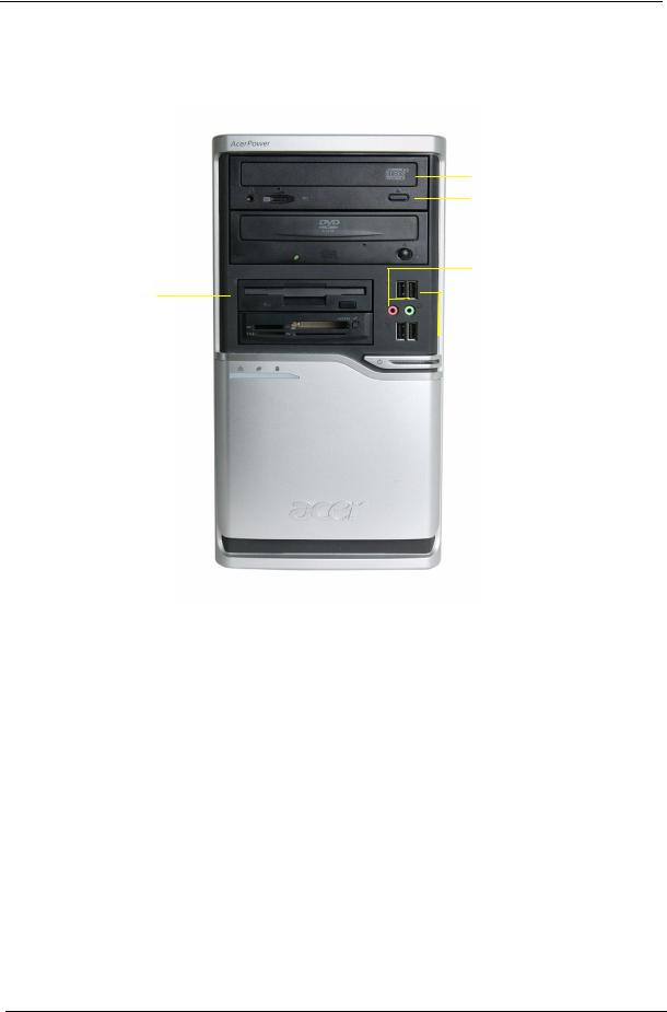
AcerPower M461 Front Panel
5
4
3
8


 2 7
2 7

6 |
|
|
|
1 |
|
|
|
||
|
|
|
|
Label |
Description |
|
|
1 |
Power-Button |
|
|
2 |
USB ports |
|
|
3 |
Microphone-in & Speaker-out/Line-out Port |
|
|
4 |
Optical drive eject button |
|
|
5 |
Optical drive |
|
|
6 |
Indicators |
|
|
7 |
Card reader |
|
|
8 |
HDD |
|
|
10 |
Chapter 1 |

AcerPower M461 Rear Panel
No. |
Description |
No. |
Description |
|
|
|
|
1 |
Power cord socket |
2 |
Voltage selector switch |
|
|
|
|
3 |
Fan aperture |
4 |
PS/2 keyboard connector |
|
|
|
|
5 |
PS/2 mouse connector |
6 |
Serial port |
|
|
|
|
7 |
Printer connector |
8 |
Monitor connector |
|
|
|
|
9 |
USB 2.0 ports |
10 |
RJ-45 Ethernet connector |
|
|
|
|
11 |
Microphone jack |
12 |
Line-out Jack |
|
|
|
|
13 |
Line-in jack |
14 |
Extension card slots |
|
|
|
|
Chapter 1 |
11 |

System Peripherals
The Aspire S Series computer consist of the system itself, and system peripherals, like a
mouse, keyboard and a set of speakers (optional). This section provides a brief description of the basic system peripherals.
Mouse (PS/2 or USB, manufacturing option)
The included mouse is a standard two-button wheel mouse. Connect the mouse to the PS/2 mouse port or USB port on the back panel of the system.
Keyboard (PS/2 or USB, manufacturing option)
Connect the keyboard to the PS/2 keyboard port or USB port on the back panel of the system.
12 |
Chapter 1 |
Speakers
For systems bundled with speakers, before powering on the system, connect the speaker cable to the audio out (external speaker) port on the back panel of the system.
For more detailed information about the speakers, please refer to the included operating instructions. NOTE: speakers are optional and the appearance might be different depending on the actual product.
Chapter 1 |
13 |

Acer eRecovery
Acer eRecovery is a tool to quickly backup and restore the system. Users can create and save a backup of the current system configuration to hard drive, CD, or DVD.
Acer eRecovery consists of the following functions:
1.Create backup
2.Restore from backup
3.Create factory default image CD
4.Re-install bundled software without CD
5.Change Acer eRecovery password
Create backup
Users can create and save backup images to hard drive, CD, or DVD.
1.Boot to Windows XP
2.Press <Alt>+<F10> to open the Acer eRecovery utility.
3.Enter the password to proceed. The default password is six zeros.
4.In the Acer eRecovery window, select Recovery settings and click Next
5.In the Recovery settings window, select Backup snapshot image and click Next.
6.Select the backup method.
Use Backup to HDD to store the backup disc image on drive D:.
Backup to optical device to store the backup disc image on CD or DVD (only available on systems that include an optical disc burner).
7. After choosing the backup method, click Next. Follow the instruction on screen to complete the process.
Restore from backup
Users can restore backup previously created (as stated in the Create backup section) from hard drive, CD, or DVD.
1.Boot to Windows XP.
2.Press <Alt>+<F10> to open the Acer eRecovery utility.
3.Enter the password to proceed. The default password is six zeros.
4.In the Acer eRecovery window, select Recovery actions and click Next.
5.Select the desired restore action and follow the onscreen instructions to complete the restore process.
Create factory default image CD
When the System CD and Recovery CD are not available, you can create them by using this feature.
1.Boot to Windows XP.
2.Press <Alt>+<F10> to open the Acer eRecovery utility.
3.Enter the password to proceed. The default password is six zeros.
4.In the Acer eRecovery window, select Recovery settings and click Next.
5.In the Recovery settings window, select Burn image to disc and click Next.
6.In the Burn image to disc window, select 01. Factory default image and click Next.
14 |
Chapter 1 |

7.Follow the instructions on screen to complete the process.
Re-install bundled software without CD
Acer eRecovery stores pre-loaded software internally for easy driver and application re-installation.
1.Boot to Windows XP.
2.Press <Alt>+<F10> to open the Acer eRecovery utility.
3.Enter the password to proceed. The default password is six zeros.
4.In the Acer eRecovery window, select Recovery actions and click Next.
5.In the Recovery settings window, select Reinstall applications/drivers and click Next.
6.Select the desired driver/application and follow the instructions on screen to re-install.
At first launch, Acer eRecovery prepares all the needed software and may take few seconds to bring up the software content window.
Change Password
Acer eRecovery and Acer disc-to-disc recovery are protected by a password that can be changed by the user. Follow the steps below to change the password in Acer eRecovery.
1.Boot to Windows XP.
2.Press <Alt>+<F10> to open the Acer eRecovery utility.
3.Enter the password to proceed. The default password is six zeros.
4.In the Acer eRecovery window, select Recovery settings and click Next.
5.In the Recovery settings window, select Password: Change Acer eRecovery password and click Next.
6.Follow the instructions on screen to complete the process.
Chapter 1 |
15 |

Acer disc-to-disc recovery
Restore without a Recovery CD
This recovery process helps you restore the C: drive with the original software content that is installed when you purchase your notebook. Follow the steps below to rebuild your C: drive. (Your C: drive will be reformatted and all data will be erased.) It is important to back up all data files before you use this option.
1.Restart the system.
2.While the Acer logo is showing, press <Alt>+<F10> at the same time to enter the recovery process.
3.The message "The system has password protection. Please enter 000000:" is displayed.
4.Enter six zeros and continue.
5.The Acer Recovery main page appears.
6.Use the arrow keys to scroll through the items (operating system versions) and press <Enter> to select.
Multilingual operating system installation
Follow the instructions to choose the operating system and language you prefer when you first power-on the system.
1.Turn on the system.
2.Acer's multilingual operating system selection menu will pop-up automatically.
3.Use the arrow keys to scroll to the language version you want. Press <Enter> to confirm your selection.
4.The operating system and language you choose now will be the only option for future recovery operations.
5.The system will install the operating system and language you choose.
16 |
Chapter 1 |

Hardware Specifications and Configurations
Processor
Item |
Specification |
|
|
Type |
Intel Prescott 775/Conroe |
Socket |
Socket T LGA 775 pin |
|
|
Speed |
System bus total up to 20.8GB/s |
|
|
FSB |
800/1600 MHz |
|
|
BIOS |
|
|
|
Item |
Specification |
|
|
BIOS code programmer |
Award |
|
|
BIOS version |
v6.0 |
|
|
BIOS ROM type |
Flash ROM |
|
|
BIOS ROM size |
4MB |
|
|
BIOS ROM package |
32-pin DIP package |
|
|
Support protocol |
ACPI 2.0, APM 1.2, SMBIOS 2.3, WFM support, ASD 1.03, |
|
PXE boot ROM, PCI 2.3 |
|
|
Boot from CD-ROM feature |
Yes |
|
|
Support to LS-120 FDD drive |
Yes |
|
|
Support to BIOS boot block feature |
Yes |
|
|
NOTE: The BIOS can be overwritten/upgraded by using the flash utility.
BIOS Hotkey List
|
Hotkey |
|
Function |
Description |
|
|
|
|
|
|
|
Delete |
Enter BIOS Setup Utility |
Press while the system is booting to |
|
||
|
|
|
|
enter BIOS Setup Utility. |
|
|
|
|
|
|
|
Main Board Major Chips |
|
|
|
|
|
|
|
|
|
|
|
|
Item |
|
|
Controller |
|
|
|
|
|
|
|
|
NorthBridge |
|
Intel 946GZ |
|
|
|
|
|
|
|
|
|
SourthBridge |
|
Intel ICH7DH |
|
|
|
|
|
|
|
|
|
AGP controller |
|
Intel 946GZ |
|
|
|
|
|
|
|
|
|
Super I/O controller |
|
ITE8718 |
|
|
|
|
|
|
|
|
|
Audio controller |
|
ALC888 |
|
|
|
|
|
|
|
|
|
LAN controller |
|
Intel 82573L |
|
|
|
|
|
|
|
|
|
HDD controller |
|
ICH7DH |
|
|
|
|
|
|
|
|
|
Keyboard controller |
|
ITE8718 |
|
|
|
|
|
|
|
|
Chapter 1 |
17 |

System Memory
Item |
Specification |
|
|
Memory slot number |
2 slot |
|
|
Support memory size per socket |
256MB to 1GB |
|
|
Support maximum memory size |
2GB |
|
|
Support memory type |
DDR2 SDRAM |
|
|
Support memory interface |
DDR2 667/533 |
|
|
Support memory voltage |
1.8V |
|
|
Support memory module package |
240-pin DIMM |
|
|
Support to parity check feature |
Yes |
|
|
Support to Error Correction Code (ECC) |
ECC checking with double-bit detect and single-bit |
feature |
correct |
Memory module combinations |
You can install memory modules in any combination as |
|
long as they match the specifications. |
|
|
NOTE: Dual channel should be enabled always when plug-in 2 same memory size DDRII memory module.
Cache Memory
|
Item |
Specification |
|
|
|
First-Level Cache Configurations |
|
|
Cache function control |
Enable/Disable by BIOS Setup |
|
|
|
|
Second-Level Cache Configurations |
|
|
|
|
|
L2 Cache RAM type |
PBSRAM |
|
|
|
|
L2 |
Cache RAM size |
up to 1MB per core(exclusive) |
|
|
|
L2 |
Cache RAM speed |
One-half the processor core clock frequency |
|
|
|
L2 |
Cache function control |
Enable/Disable by BIOS Setup |
|
|
|
L2 |
Cache scheme |
Fixed in write-back |
|
|
|
Video Interface
Item |
Specification |
|
|
Video controller |
Intel ICH7DH |
|
|
Video controller resident bus |
PCIE |
|
|
Video Interface |
x16 |
|
|
AGP Slot |
1 |
|
|
Audio Interface |
|
|
|
Item |
Specification |
|
|
Audio controller |
ICH7DH |
|
|
Audio controller Type |
AC’97, ALC888 |
|
|
Audio Channel |
7.1ch |
|
|
Audio function control |
Enable/disable by BIOS Setup |
|
|
18 |
Chapter 1 |

Audio Interface
Item |
Specification |
|
|
Mono or stereo |
Stereo |
|
|
Resolution |
support up to 24 bit |
|
|
Compatibility |
Sound Blaster Pro/16 compatible |
|
Mixed digital and analog high performance chip |
|
Enhanced stereo full duplex operation |
|
High performance audio accelerator and AC’97 support |
|
Full native DOS games compatibility |
|
Virtual FM enhances audio experience through real-time FM-to- |
|
Wavetable conversion |
|
MPU-401(UART mode) interface for wavetable synthesizers and |
|
MIDI devices |
|
Integrated dual game port |
|
Meets AC’97and WHQL specifications |
|
|
Music synthesizer |
Yes, internal FM synthesizer |
|
|
Sampling rate |
DACs: 44.1k/48k/96k/192k Hz |
|
ADCs: 44.1k/48k/96k Hz |
|
|
MPU-401 UART support |
Yes |
|
|
Microphone jack |
Supported |
|
|
Headphone jack |
Supported |
|
|
IDE Interface |
|
|
|
Item |
Specification |
|
|
IDE controller |
Intel ICH7DH |
|
|
IDE controller resident bus |
PCI bus |
|
|
Number of IDE channel |
1 |
|
|
Support IDE interface |
E-IDE (up to PIO mode-4 and Ultra DMA 33/66/100/133), ANSIS |
|
ATA rev.3.0 ATAPI |
|
|
Support bootable CD-ROM |
Yes |
|
|
Floppy disk drive Interface |
|
|
|
Item |
Specification |
|
|
Floppy disk drive controller |
ITE8718 |
|
|
Floppy disk drive controller resident |
LPC bus |
bus |
|
|
|
Support FDD format |
should support 1.44MB/3mode 3.5” Devices |
|
|
Chapter 1 |
19 |

Parallel Port
Item |
Specification |
|
|
Parallel port controller |
ITE8718 |
Parallel port controller resident bus |
ISA bus |
|
|
Number of parallel ports |
1 |
|
|
Support ECP/EPP |
Bi-directional SPP / ECP / EPP V1.7&V1.9 |
|
|
Connector type |
25-pin D-type female connector |
|
|
Parallel port function control |
Enable/disable by BIOS Setup |
|
|
Serial Port |
|
|
|
Item |
Specification |
|
|
Serial port controller |
ITE8718 |
|
|
Serial port controller resident bus |
ISA bus |
|
|
Number of serial port |
2 |
|
|
16550 UART support |
Yes |
|
|
Connector type |
9-pin D-type female connector |
|
|
Features |
Support IrDA1.0/ASKIR protocols, smart card reader protocols |
|
|
USB Port |
|
|
|
Item |
Specification |
|
|
Universal HCI |
USB 2.0 |
|
|
USB Class |
Support legacy keyboard for legacy mode |
|
|
USB Number |
support up to 8 ports |
|
|
Environmental Requirements
Item |
|
|
|
Specifications |
|
|
|
|
|
|
|
|
|
|
|
Temperature |
|
|
|
|
|
|
|
|
|
|
|
|
|
|
|
Operating |
|
+5°C ~ +35°C |
|
|
|
|
|
|
|
|
|
|
|
|
|
Non-operating |
|
-20 ~ +60°C (Storage package) |
|
|
|||
|
|
|
|
|
|
|
|
Humidity |
|
|
|
|
|
|
|
|
|
|
|
|
|
|
|
Operating |
|
15% to 80% RH |
|
|
|
|
|
|
|
|
|
|
|
|
|
Non-operating |
|
10% to 90% RH |
|
|
|
|
|
|
|
|
|
|
|
|
|
Vibration |
|
|
|
|
|
|
|
|
|
|
|
|
|
|
|
Operating (unpacked) |
|
5 ~ 500 Hz:2.20g RMS random, 10 minutes per axis in all 3 axes |
|||||
|
|
5 ~500 Hz: 1.09g RMS random, 1 hour per axis in all 3 axes |
|||||
|
|
|
|
|
|
|
|
Power Management |
|
|
|
|
|
|
|
|
|
|
|
|
|
|
|
|
S1 |
S3 |
|
S4 |
S5 |
|
|
Devices |
(Suspend to |
|
(Suspend to |
|
|||
(Idle) |
|
(Shut Down) |
|
||||
|
RAM) |
|
DIsk) |
|
|||
|
|
|
|
|
|
||
|
|
|
|
|
|
|
|
Power Button |
Enabled |
Enabled |
|
Enabled |
Disabled |
|
|
|
|
|
|
|
|
|
|
20 |
Chapter 1 |

Power Management
|
S1 |
S3 |
S4 |
S5 |
|
Devices |
(Suspend to |
(Suspend to |
|||
(Idle) |
(Shut Down) |
||||
|
RAM) |
DIsk) |
|||
|
|
|
|||
|
|
|
|
|
|
USB Keyboard |
Enabled |
Enabled |
Disabled |
N/A |
|
|
|
|
|
|
|
LAN |
Disabled |
Disabled |
Disabled |
Disabled |
|
|
|
|
|
|
|
RTC |
Disabled |
Enabled |
Disabled |
Disabled |
|
|
|
|
|
|
|
Modem (Ring) |
Disabled |
Disabled |
Disabled |
N/A |
|
|
|
|
|
|
Chapter 1 |
21 |

Power Management Function (ACPI support function)
Device Standby Mode
Independent power management timer for hard disk drive devices (0-15 minutes, time step=1 minute).
Hard disk drive goes into Standby mode (for ATA standard interface). Disable V-sync to control the VESA DPMS monitor.
Resume method: device activated (Keyboard for DOS, keyboard & mouse for Windows). Resume recovery time: 3-5 sec.
Global Standby Mode
Global power management timer (2-120 minutes, time step=10 minute). Hard disk drive goes into Standby mode (for ATA standard interface). Disable H-sync and V-sync signals to control the VESA DPMS monitor.
Resume method: Return to original state by pushing external switch button, modem ring in, keyboard and mouse for APM mode.
Resume recovery time: 7-10 sec.
Suspend Mode
Independent power management timer (2-120 minutes, time step=10 minutes) or pushing external switch button.
CPU goes into SMM.
CPU asserts STPCLK# and goes into the Stop Grant State. LED on the panel turns amber colour.
Hard disk drive goes into SLEEP mode (for ATA standard interface). Disable H-sync and V-sync signals to control the VESA DPMS monitor. Ultra I/O and VGA chip go into power saving mode.
Resume method: Return to original state by pushing external switch button, modem ring in, keyboard and mouse for APM mode.
Return to original state by pushing external switch button, modem ring in and USB keyboard for ACPI mode.
ACPI
ACPI specification 1.0b.
S0, S1, S3 and S5 sleep state support.
On board device power management support.
On board device configuration support.
22 |
Chapter 1 |
Loading...