


Acer
Veriton M265 Service Guide
PRINTED IN TAIWAN
I
Revision History
Please refer to the table below for the updates made on Veriton M265 Service Guide
Date |
Chapter |
Updates |
|
|
|
|
|
|
|
|
|
II
Copyright
Copyright © 2010 by Acer Incorporated. All rights reserved. No part of this publication may be reproduced, transmitted, transcribed, stored in a retrieval system, or anslated into any language or computer language, in any form or by any means, electronic, mechanical, magnetic, optical, chemical, manual or otherwise, without the prior written permission of Acer Incorporated.
Disclaimer
The information in this guide is subject to change without notice.
Acer Incorporated makes no representations or warranties, either expressed or implied, with respect to the contents hereof and specifically disclaims any warranties of merchantability or fitness for any particular purpose. Any Acer Incorporated software described in this manual is sold or licensed "as is". Should the programs prove defective following their purchase, the buyer (and not Acer Incorporated, its distributor, or its dealer) assumes the entire cost of all necessary servicing, repair, and any incidental or consequential damages resulting from any defect in the software.
Acer is a registered trademark of Acer Corporation. Intel is a registered trademark of Intel Corporation.
Pentium 4 and Celeron are trademarks of Intel Corporation.
Other brand and product names are trademarks and/or registered trademarks of their respective holders.
III
Conventions
The following conventions are used in this manual:
SCREEN ESSAGES |
Denotes actual messages that appear on screen. |
|
|
NOTE |
Gives bits and pieces of additional information |
|
related to the current topic. |
WARNING |
Alerts you to any damage that might result from |
|
doing or not doing specific actions. |
CAUTION |
Gives precautionary measures to avoid possible |
|
hardware or software problems. |
IMPORTANT |
Remind you to do specific actions relevant to the |
|
accomplishment of procedures. |
IV
Preface
Before using this information and the product it supports, please read the following general information.
1.This Service Guide provides you with all technical information relating to the BASIC CONFIGURATION decided for Acer's "global" product offering. To better fit local market requirements and enhance product competitiveness, your regional office MAY have decided to extend the functionality of a machine (e.g. add-on card, modem, or extra memory capability). These LOCALIZED FEATURES will NOT be covered in this generic service guide. In such cases, please contact your regional offices or the responsible personnel/channel to provide you with further technical details.
2.Please note WHEN ORDERING FRU PARTS, that you should check the most up-to-date information available on your regional web or channel. If, for whatever reason, a part number change is made, it will not be noted in the printed Service Guide. For ACER-AUTHORIZED SERVICE PROVIDERS, your Acer office may have a DIFFERENT part number code to those given in the FRU list of this printed Service Guide. You MUST use the list provided by your regional Acer office to order FRU parts for repair and service of customer machines.
V
Chapter 1 System Specifications 1
F e a t u r e s … … … … … … … … … … … … … … … … … … … … … … … … … … … … … … … … … … … . . . 1 M a i n b o a r d P l a c e m e n t … … … … … … … … … … … … … … … … … … … … … … … … 7 B l o c k D i a g r a m … … … … … … … . . … … … … … … … … … … … . … … … … … … … … 8 V e r i t o n M 2 6 5 F r o n t P a n e l … … … … … … … … … … … … … … … . . … … . … … … . . 9 Ve r i t o n M 2 6 5 R e a r P a n e l … … … … … … … . . … … … … … … … … … … … . … … … … … … … … 1 0 H a r d w a r e S p e c i f i c a t i o n s a n d C o n f i g u r a t i o n s … … … … … … … . … … . … … . . 1 1 P o w e r M a n a g e m e n t F u n c t i o n ( A C P I s u p p o r t f u n c t i o n ) … … … … … … … … … … . . … . . . 1 6
Chapter 2 System Utilities 17
S e t u p U t i l i t y M e n u s … … … … … … … … … … … … … … … … … … … … … … … … … … … … . . 1 8 P r o d u c t I n f o r m a t i o n … … … … … … … … … … … … … … … … … … … … … … … … … … … . . 2 0 St a n d a r d C M O S F e a t u r e s … … … … … … … … … … … … . … … … … … … … … … … … … … … 2 1 A d v a n c e d B I O S F e a t u r e s … … … … … … … … … … … … … … … . . … … … … … … … … 2 2 A d v a n c e d C h i p s e t S e t u p … … … … … … … … … … … … … … … . . … … … … … … … … 2 4 I n t e g r a t e d P e r i p h e r a l s … … … … … … … … … … . . . … … … … … … … … … … … … … … … … . . 2 5 P o w e r M a n a g e m e n t … … … … … … … … … … … … … … … … … … … … … … … … . … … … . … 2 7 P n P / P C I C o n f i g u r a t i o n … … … … … … … … … … … … … … … … … … … … … … … . . . 2 9 P C H e a l t h S t a t u s … … … … … … … … … … … … … … … … … … … … … … … . . . … … . … … … 3 0 F r e q u e n c y C o n t r o l … … … … … . . … … … … … … … … … … . … … … … … . … … … … 3 1 L o a d O p t i m i z e d D e f a u l t s … … … … … . . … … … … … … … … … … . … … . … … . … … … 3 2 S e t S u p e r v i s o r P a s s w o r d … … … … … . . … … … … … … … … … … . … … … … … … … … . 3 3 S e t U s e r P a s s w o r d … … … … … . . … … … … … … … … … … . … … … … . … … … … … . … 3 4 S a v e & E x i t S e t u p … … … … … … … … … … … … … … … … … … … . … … … … … … . … 3 5 E x i t W i t h o u t S a v i n g … … … … … … … … … … … … … … … … … … … . … … . . … … . … 3 6
Chapter 3 Machine Disassembly and Replacement 37
G e n e r a l I n f o r m a t i o n … … … … … … … … … … … … … … … … … … … … … . 3 8 D i s a s s e m b l y P r o c e d u r e … … … … … … … … … … … … … … … … … … … … 3 9 V e r i t o n M 2 6 5 D i s a s s e m b l y P r o c e d u r e … … … … … . … . . … … 4 0
Chapter 4 Troubleshooting 54
Chapter 5 Jumper and Connector Information 55
J u m p e r S e t t i n g … … … … … … … … … … … … … … … … … … … . . … … … … … … . . 4 7
Chapter 6 FRU (Field Replaceable Unit) List 64
E x p l o d e d D i a g r a m … … … … … … … … … … … … … … … … … … … … … … . 6 5
V e r i t o n M 2 6 5 F R U L i s t … … … … … … … … … … … … … … … … … … … . 6 7
VI

System Specifications
Features
Operating System
Microsoft Windows Vista Business
Microsoft Windows Vista Ultimate
Microsoft Windows Vista Home Premium
Microsoft Windows Vista Home Basic
Microsoft Windows Vista Starter
Microsoft Windows XP Home/Professional
Microsoft Windows Vista Home Basic SP2
Microsoft Windows Vista Home Premium SP2
Microsoft Windows Vista Business SP2
Microsoft Windows Vista (64 bit) SP2
Microsoft Windows XP Professional SP3
Linpus Linux
Microsoft Windows 7 Professional 32-bit
Microsoft Windows 7 Home Premium 32-bit
Microsoft Windows 7 Home Basic 32-bit
Microsoft Windows 7 Professional 64-bit
Processor
Socket Type: Intel® Socket T LGA 775 pin
Processor Type:
Intel Celeron(Conore L) /Pentium Dual Core / Core 2 Duo / Core2
Quad CPUs FSB 800/1066/1333 MHz CPUs
1

Chipset
North Bridge: Intel G31
South Bridge: Intel ICH 7DH
PCB
Form Factor: Micro ATX
Dimension/Layer: 244mm x244mm
Memory
Memory Type: DDR II 800
Support single channel 64 bit mode with maximum memory size up to
4GB
Support un-buffered DIMM 2 only
DIMM Slot: 2
Memory Max: 512MB / 1GB / 2GB DDR2 memory technologies
Capacity: Up to 1 GB per DIMM with maximum memory size up to 4 GB
PCI
PCI Express Slot Type: x16
PCI Express x16 Slot Quantity: 1
Support ADD2/MEC card
PCI Express Slot Type: x1
PCI Express x1 Slot Quantity: 1
PCI Slot
PCI Slot Quantity: 2
FDD
Slot Quantity: 1
Design Criteria:
Should support 1.44MB/3 mode 3.5” Devices
2

IDE
Slot Type: 40pin PATA IDE slot
Slot Quantity: 1
Transfer rate support:
PIO Mode: 0/1/2/3/4
ATA mode: 33/66/100/133
Storage Type support:
HDD/CD-ROM/CD-RW/DVD-ROM/DVD-RW/DVD+RW/DVD Dual/DVD SuperMultiPlus/HD DVD/BlueRay DVD
SATA
Slot Type: SATA slot
Slot Quantity: 4
Storage Type support:
HDD/CD-ROM/CD-RW/DVD-ROM/DVD-RW/DVD+RW/DVD Dual/DVD Super Multi Plus / Blue-Ray ODD
Audio
Chip : HD audio codec ALC888S HD codec 7.1
On board HD internal speaker header for Veriton SKU
Connectors support:
Rear 6 jack follow HD audio definition, example as below
Audio jacks color coding: should meet Microsoft Windows Logo Program Device Requirements: Audio-0002
1 S/PDIF-out header (1*4)
1 front panel audio header (2*5)
1 internal speaker header (2*4)
Add HD de-pop CKT (the attachment is the reference, please
3

propose your solution)
S/N ratio: 90 dB at rear output jack
BIOS should meet MS Pin Configuration Guidelines for High Definition Audio Devices
LAN
Gigabit Ethernet . RTL8111B
Port: 1 x RJ45 rear port for Gigabit Ethernet
Design Criteria:
Should be worked under 10/100/1000Mbs environment
Reserved disable function on BIOS side. Default is enabled
USB
Controller: Intel ICH7DH
Ports Quantity: 8
4 back panel ports
On-board: 2 2*5 headers
2 ports for front daughter board
4 ports for rear I/O
2 ports for internal card reader.
Connector Pin: standard Intel FPIO pin definition
Data transfer rate support:
USB 2.0/1.1
1394
Controller: VIA 6308P 1394 controller (For Aspire M5630/M3630,Veriton S460)
Connector Quantity: 2
1 rear 6pin IEEE1394 port
4
1 2x5pin onboard jumper
BIOS
BIOS Type: Phoenix Award or AMI Kernel with Acer skin
4Mb Flash BIOS
Note:
Boot ROM should be included (PXE function should be built in with default and RPL function is optional by service BIOS)
Compliant with latest ASF 2.0 spec
Compliant with latest SMT 2.0 spec
Compliant with latest Intel Virtualization Technology spec
I/O Connector
Controller: Super I/O ITE 8718FX (F stepping or after; must full support Intel platform) Rear I/O Connector
1 Parallel port,
1 serial port
1 D-Sub VGA port
1 RJ45 LAN port
4 USB ports
7.1 channel phone jack ( 6 audio jacks)
1 6-pin 1394 port
On-board connectors
1 LGA 775 CPU socket
2 DDR2 memory sockets
1 PCI Express x16 slot
1 PCI Express x 1 slot
2 PCI slots
5

1 FDD slot
4 SATA2 connectors
5 pin Intel FPIO specification USB pin connectors (follow Intel FPIO standard Specification)
5 pin Intel FPIO spec. Microphone In/ Headphone Out pin connectors
1 serial port 2*5 pin connector (2nd serial port)
1 HD audio digital header
4 pin CPU Fan connector
3 pin System FAN connector with linear circuit
4 pin + 4pin ATX interface PS3/PS2 SPS connector
7 pin front panel IO header
1394 header
Jumper for clear CMOS
Color management for on board connecters (please refer to Acer spec)
Header for CIR & IR blaster function (Check ITE Solution)
Power Supply
PSP Type: 250W/300W
6

Main board Placement
7
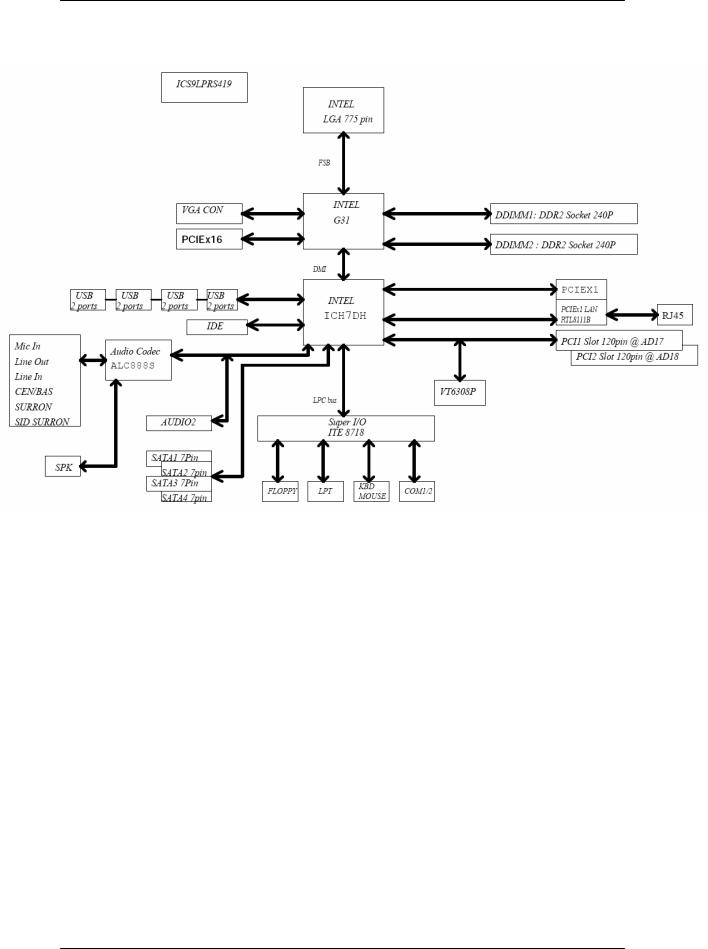
Block Diagram
8
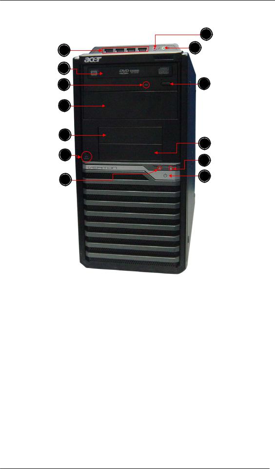
Veriton M265 Front Panel
Label |
Description |
1 |
USB ports |
|
|
2 |
Master optical drive |
|
|
3 |
ODD activity indicator |
|
|
4 |
Slave bay door(Slave ODD) |
|
|
5 |
Master FDD bay(Optional by SKU FDD>Card Reader>Internal Speaker) |
|
|
6 |
Recover jack |
|
|
7 |
LAN activity indicator |
|
|
8 |
Power button |
|
|
9 |
HDD activity indicator |
|
|
10 |
Slave bay(Optional by SKU Card Reader>Internal Speaker) |
|
|
11 |
Optical drive button |
|
|
12 |
Headphone/Speaker-out/line-out jack |
|
|
13 |
Microphone-in jack |
|
|
9
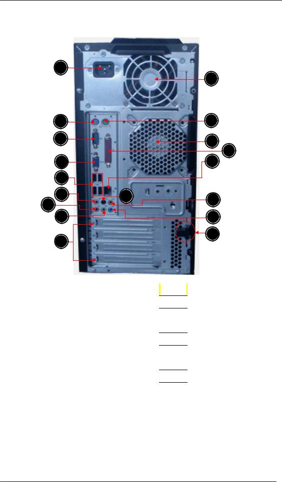
Veriton M265 Rear Panel
1
17
2 |
|
16 |
3 |
|
15 |
|
|
|
|
|
14 |
4 |
|
13 |
5 |
|
|
6 |
8 |
12 |
7 |
|
|
|
|
|
8 |
|
11 |
|
|
10 |
9
Label |
Description |
Label |
|
Description |
1 |
Power connector |
10 |
|
Lock Handle |
|
|
|
|
|
2 |
PS2 keyboard port |
11 |
|
Line-in jack |
|
|
|
|
|
3 |
Serial port |
12 |
|
Center speaker/subwoofer jack |
|
|
|
|
|
4 |
VGA port |
13 |
|
RJ45 LAN connector |
|
|
|
|
|
5 |
USB 2.0 ports |
14 |
|
Parallel port |
|
|
|
|
|
6 |
Side Surround jack |
15 |
|
System Fan |
|
|
|
|
|
7 |
Microphone/speaker-out/line-in jack |
16 |
|
PS2 mouse port |
|
|
|
|
|
8 |
Line-out jack |
17 |
|
Fan aperture |
|
|
|
|
|
9 |
Expansion slot (Graphics card and TV tuner card and Mode card etc.) |
|||
|
|
|
|
|
10

Hardware Specifications and Configurations
Processor
Item |
Specification |
Type |
Intel Celeron(Conore L) /Pentium Dual Core / Core 2 Duo |
|
/ Core2 Quad CPUs |
Socket |
LGA 775 pin |
FSB |
800/1066 /1333 MHz |
Minimum operating |
0 MHz (If Stop CPU Clock in Sleep State in BIOS Setup is |
speed |
set to Enabled.) |
BIOS |
|
Item |
|
Specification |
BIOS code programmer |
Phoenix Award or AMI Kernel with Acer skin |
|
|
|
|
BIOS version |
V6.0 |
|
BIOS ROM type |
SPI Flash |
|
BIOS ROM size |
4 Mb |
|
|
|
|
Support protocol |
PXE 2.1 DMI V.2.0(s)or 2.1 SMBIOS 2.5 |
|
|
ACPI v3.0b |
|
Device Boot Support |
- |
1st priority: SATA HDD |
|
- 2nd priority: CD-ROM |
|
|
- |
3rd priority: FDD |
|
- |
4th priority: LAN |
|
- 5th priority: USB device |
|
Support to LS-120 drive |
YES |
|
|
|
|
Support to BIOS boot block feature |
YES |
|
|
|
|
11

BIOS Hotkey List
Hotkey |
Function |
Description |
Del |
Enter BIOS Setup Utility |
Press while the system is booting to enter |
|
|
BIOS Setup Utility. |
|
|
|
Main Board Major Chips
Item |
Specification |
North Bridge |
Intel G31 |
South Bridge |
Intel ICH 7DH |
APG controller |
Intel G31 |
Super I/O controller |
ITE 8718FX |
Audio controller |
Realtek HD audio codec ALC888S HD codec 7.1 (co-lay |
|
with ALC888S) |
LAN controller |
RTL8111B |
HDD controller |
ITE 8718FX |
Keyboard controller |
ITE 8718FX |
Memory Combinations |
|
Slot |
Memory |
Total Memory |
Slot 1 |
512MB, 1GB, 2GB |
512MB~2GB |
Slot 2 |
512MB, 1GB, 2GB |
512MB~2GB |
Maximum System Memory Supported |
512MB~4GB |
|
|
|
|
12

System Memory
Item |
Specification |
Memory slot number |
2 slot |
Support Memory size per socket |
512MB/1GB/2GB |
Support memory type |
DDR2 |
Support memory interface |
DDR2 800MHz |
Support memory voltage |
1.8V |
Support memory module package |
240-pin DDR2 |
Support to parity check feature |
Yes |
|
|
Support to error correction code (ECC) feature |
No |
Memory module combinations |
You can install memory modules |
|
in any combination as long as |
|
they match the above |
|
specifications. |
Audio Interface |
|
Item |
Specification |
|
Audio controller |
Intel ICH 7DH |
|
Audio controller type |
ALC888S |
|
Audio channel |
codec 7.1 |
|
Audio function control |
Enable/disable by BIOS Setup |
|
Mono or stereo |
Stereo |
|
Compatibility |
Sound Blaster Pro/16 compatible Mixed digital and analog |
|
|
high performance chip Enhanced stereo full duplex |
|
|
operation High performance audio accelerator and AC’97 |
|
|
support Full native DOS games compatibility Virtual FM |
|
|
enhances audio experience through real-time |
|
|
FM-to-Wavetable conversionMPU-401 (UART mode) |
|
|
interface for Wavetable synthesizers and MIDI devices |
|
|
Integrated dual game port Meets AC’97and WHQL |
|
|
specifications |
|
|
|
|
Music synthesizer |
Yes, internal FM synthesizer |
|
Sampling rate |
48 KHz (max.) |
|
MPU-401 UART support |
Yes |
|
Microphone jack |
Supported |
|
Headphone jack |
Supported |
|
|
|
|
|
13 |
|

SATA Interface
Item |
Specification |
SATA controller |
Intel ICH 7DH |
SATA controller resident bus |
PCI bus |
Number of SATA channel |
SATA X 4 |
Support bootable CD-ROM |
YES |
Floppy disk drive Interface
Item
Floppy disk drive controller
Floppy disk drive controller resident bus
Support FDD format
Specification
ITE 8718FX ISA bus
360KB, 720KB, 1.2MB, 1.44MB, 2.88MB
Serial Port
Item |
Specification |
Serial port controller |
ITE 8718FX |
Serial port controller resident bus |
ISA bus |
|
|
Number of serial port |
2 |
16550 UART support |
Yes |
Connector type |
9-pin D-type female connector |
|
|
Optional serial port I/O address (via BIOS |
COM1: 2F8h, 3E8h, 2E8h |
setup) |
COM2: 3E8h, 3F8h, 2F8h |
Optional serial port IRQ (via BIOS setup) |
COM1: IRQ 3, and 4 |
|
COM2: IRQ 4, and 3 |
USB Port |
|
Item |
Specification |
Universal HCI |
USB 2.0 |
USB Class |
Support legacy keyboard for legacy mode |
|
|
USB Connectors Quantity |
4 back panel ports |
|
2 ports for front daughter board |
|
2 ports for 3.5’’ card reader module |
14
Environmental Requirements
Item
Temperature
Operating
Non-operating
Humidity
Operating
Non-operating
Vibration
Operating (unpacked)
Specification
+5°C ~ +35°C
-20 ~ +60°C (Storage package)
15% to 80% RH
10% to 90% RH
5 ~ 500 Hz: 2.20g RMS random, 10 minutes per axis in all 3 axes
5 ~500 Hz: 1.09g RMS random, 1 hour per axis in all 3 axes
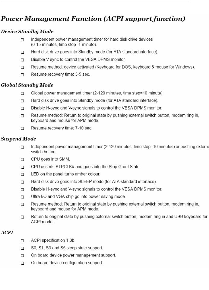
Power Management
Devices |
S1 |
S3 |
S4 |
S5 |
|
|
|
|
|
Power Button |
V |
V |
V |
V |
|
|
|
|
|
USB Keyboard/Mouse |
V |
V |
N/A |
N/A |
|
|
|
|
|
PME |
Disabled |
Disabled |
Disabled |
Disabled |
|
|
|
|
|
RCT |
Disabled |
Disabled |
Disabled |
Disabled |
|
|
|
|
|
WOR |
Disabled |
Disabled |
Disabled |
Disabled |
|
|
|
|
|
Devices wake up from S3 should be less than
Devices wake up from S5 should be less than 10 seconds
15
16

System Utilities
The manufacturer or the dealer already configures most systems. There is no need to run Setup when starting the computer unless you get a Run Setup message.
The Setup program loads configuration values into the battery-backed nonvolatile memory called CMOS RAM.
This memory area is not part of the system RAM.
NOTE: If you repeatedly receive Run Setup messages, the battery may be bad/flat. In this case, the system cannot retain configuration values in CMOS.
Before you run Setup, make sure that you have saved all open files. The system reboots immediately after you exit Setup.
17
Setup Utility Menus
Power on the computer and the system will start POST (Power On Self Test) process. When the message of “Press DEL to enter SETUP” appears on the screen, press the key of [Delete] to enter the setup menu.
NOTE: If the message disappears before you respond and you still wish to enter Setup, restart the system by turning it OFF and On. You may also restart the system by simultaneously pressing [Ctrl+ Alt+ Delete].
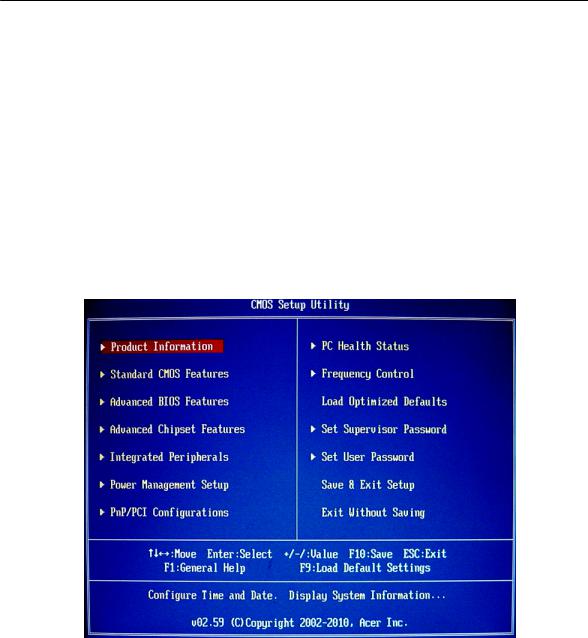
The Setup Utility main menu then appears:
The items in the main menu are explained below:
|
Parameter |
Description |
|
|
Production Information |
This page shows the relevant information of the main board |
|
|
|
|
|
|
Standard CMOS Features |
This setup page includes all the items in standard compatible BIOS |
|
|
|
|
|
|
Advance BIOS Features |
This setup page includes all the items of Award special enhanced features |
|
|
|
|
|
|
Advance Chipset |
This setup page includes all advanced chipset features |
|
|
Features |
|
|
|
|
|
|
|
Integrated Peripherals |
This setup page includes all onboard peripherals |
|
|
|
|
|
|
|
|
|
|
|
18 |
|

Power Management |
This setup page includes all the items of Green function features |
Setup |
|
|
|
PnP/PCI Configuration |
This setup page includes all configurations of PCI & PnP ISA resources |
|
|
PC Health Status |
This setup page is the System auto detect Temperature, voltage, and fan speed |
|
|
Frequency Control |
This setup page is the System Frequency setup |
|
|
Load Optimized Defaults |
Load Optimized Settings Default Settings indicates the value of the system |
|
parameters which the system would be in best performance configuration |
|
|
Set Supervisor Password |
Change, set or disable password. It allows you to limit access to the system |
|
and Setup, or just to Setup |
|
|
Set User Password |
Change, set or disable password. It allows you to limit access to the System |
|
|
Save & Exit Setup |
Save CMOS value settings to CMOS and exit setup |
|
|
Exit Without Saving |
Abandon all CMOS value changes and exit setup |
|
|
19
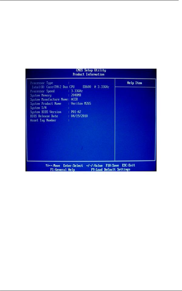
Product Information
The screen below appears if you select Product Information from the main menu: The Product Information menu contains general data about the system, such as the product name, serial number, BIOS version, etc. This information is necessary for troubleshooting (maybe required when asking for technical support).
The following table describes the parameters found in this menu:
Parameter |
Description |
Processor Type |
Type of CPU installed on the system. |
|
|
Processor Speed |
Speed of the CPU installed on the system. |
|
|
System Memory |
Total size of system memory installed on the system. |
|
|
Product Name |
Product name of the system |
|
|
System Serial Number |
Serial number of the system. |
|
|
System BIOS Version |
Version number of the BIOS setup utility. |
|
|
BIOS Release Date |
Date when the BIOS setup utility was released |
|
|
Asset Tag Number |
Asset tag number of this system. |
|
|
20
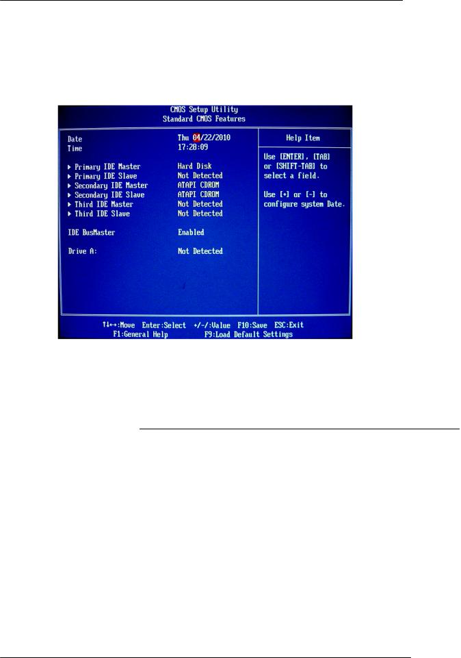
Standard CMOS Features
Select standard CMOS features from the main menu to configure some basic parameters in your system the following screen shows the standard CMOS features menu:
The following table describes the parameters found in this menu.
Parameter |
Description |
Options |
System Date |
Set the date following the weekday-month-day-year format. |
|
|
|
|
System Time |
Set the system time following the hour-minute-second format. |
|
|
|
|
Primary IDE Master/Slave |
Allows you to configure the hard disk drive connected to the master port of |
|
|
IDE channel. To enter the IDE Master or Slave setup, press [Enter]. The IDE |
|
Secondary IDE Master/Slave |
||
|
CD-ROM is always automatically detected. |
|
Third IDE Master/Slave |
|
|
|
|
|
IDE BusMaster |
When enabled, BIOS uses PCI bus-mastering for |
Enabled |
|
reading/writing to IDE drives. |
Disabled |
|
|
|
Drive A |
The category identifies the types of floppy disk drive A |
Disabled |
|
that has been installed in the computer.. |
720 KB 3.5 inch |
|
|
1.44 MB 3.5 inch |
|
|
2.88 MB 3.5 inch |
|
|
Not Detected |
|
|
|
21
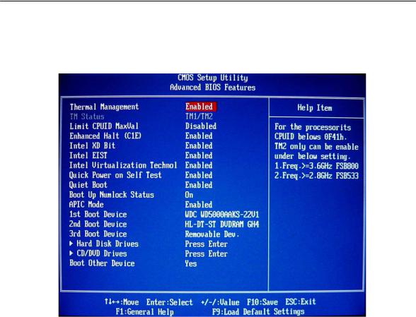
Advanced BIOS Features
The following screen shows the Advanced Setup:
The following table describes the parameters found in this menu.
|
Parameter |
Description |
Options |
||
|
Thermal Management |
For the Processor its CPUID bellows 0F41h.TM2 only can be |
Enabled |
||
|
|
enable under below setting. |
Disabled |
||
|
|
1. |
Freq.>=3.66GHz FSB800 |
|
|
|
|
2. |
Freq.>=2.86GHz FSB533 |
|
|
|
|
|
|
||
|
Enhanced Halt (C1E) |
This should be enabled in order to enable or disable “Enhanced |
Enabled |
||
|
|
Halt sate. |
Disabled |
||
|
|
|
|
||
|
Intel XD Bit |
When enabled, the processor disables code execution when a |
Enabled |
||
|
|
worm attempts to insert a code in the buffer preventing damage |
Disabled |
||
|
|
and worm propagation. |
|
|
|
|
|
|
|
||
|
Intel EIST |
When enabled, this feature allows the OS to reduce power |
Enabled |
||
|
|
consumption. |
Disabled |
||
|
|
When disabled, the system operates at maximum CPU speed. |
|
|
|
|
|
|
|
||
|
Intel Virtualization |
Enables or disables the Virtualization Technology (VT) |
Enabled |
||
|
Technology |
availability. If enabled, a virtual machine manager (VMM) can |
Disabled |
||
|
|
utilize the additional hardware virtualization capabilities provided |
|
|
|
|
|
by this technology. |
|
|
|
|
|
Note: A full reset is required to change the setting. |
|
|
|
|
|
|
|
|
|
|
|
|
|
|
|
|
|
|
|
22 |
|

Quick Power On Self |
This feature allows the system to skip certain tests while booting. |
Enabled |
Test |
When this function is enabled, it will decrease the time needed to |
Disabled |
|
boot the system, which means to quick power on self test |
|
|
function |
|
|
|
|
Quiet Boot |
When enabled, the BIOS splash screen displays during startup. |
Enabled |
|
When disabled, the diagnostic screen displays during startup. |
Disabled |
|
|
|
Boot Up NumLock |
Sets the NumLock status when the system is powered on. |
On |
Status |
Setting to On will turn on the NumLock key when the system is |
Off |
|
powered on. Setting to Off will allows users to use the arrow keys |
|
|
on the numeric keypad. |
|
|
|
|
APCI Mode |
This item allows you to enable or disable the APIC (Advanced |
Enabled |
|
Programmable Interrupt Controller) mode. APIC provides |
Disabled |
|
symmetric multi-processing (SMP) for systems. |
|
|
|
|
1st/2nd/3rd Boot Device |
Specifies the boot order from the available devices. |
Hard Disk |
|
|
DVD |
|
|
Removable |
|
|
|
Hard Disk Drive |
Press Enter to access the Hard Disk Drive Priority submenu and specify the boot |
|
|
device priority sequence from available hard drives. |
|
|
|
|
CD/DVD Drive |
Press Enter to access the Removable Device Priority submenu and specify the boot |
|
|
device priority sequence from available removable drives. |
|
|
|
|
Boot Other Device |
When it is enabled, the system searches all other possible |
Yes |
|
locations for an operating system. If it fails to find on in the |
No |
|
devices specified under the first, second, and third boot devices. |
|
|
|
|
23
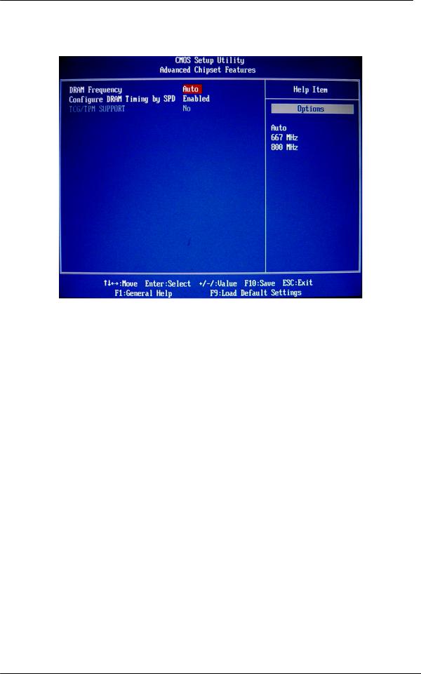
Advanced Chipset Features
The following table describes the parameters found in this menu.
Parameter |
Description |
Options |
DRAM frequency |
This item allows you to select CPU frequency of the system. |
Atuo |
|
|
667Mhz |
|
|
800MHZ |
|
|
|
Configure DRAM |
This item allows DRAM Timing in accordance with SPD were |
Enabled |
Timing by SPD |
determined automatically by the BIOS configuration |
Disabled |
|
|
|
24
 Loading...