


 Loading...
Acer Travelmate 4280, Travelmate 4260, Travelmate 4230, Travelmate 4200, Travelmate 4200z Service Manual
...TravelMate 4200 Series
Service Guide
Service guide files and updates are available on the ACER/CSD web; for more information, please refer to http://csd.acer.com.tw
PRINTED IN TAIWAN

Revision History
Please refer to the table below for the updates made on TravelMate 4200 service guide.
Date |
Chapter |
Updates |
|
|
|
|
|
|
|
|
|
|
|
|
II

Copyright
Copyright © 2005 by Acer Incorporated. All rights reserved. No part of this publication may be reproduced, transmitted, transcribed, stored in a retrieval system, or translated into any language or computer language, in any form or by any means, electronic, mechanical, magnetic, optical, chemical, manual or otherwise, without the prior written permission of Acer Incorporated.
Disclaimer
The information in this guide is subject to change without notice.
Acer Incorporated makes no representations or warranties, either expressed or implied, with respect to the contents hereof and specifically disclaims any warranties of merchantability or fitness for any particular purpose. Any Acer Incorporated software described in this manual is sold or licensed "as is". Should the programs prove defective following their purchase, the buyer (and not Acer Incorporated, its distributor, or its dealer) assumes the entire cost of all necessary servicing, repair, and any incidental or consequential damages resulting from any defect in the software.
Acer is a registered trademark of Acer Corporation. Intel is a registered trademark of Intel Corporation.
Pentium and Pentium II/III are trademarks of Intel Corporation.
Other brand and product names are trademarks and/or registered trademarks of their respective holders.
III

Conventions
The following conventions are used in this manual:
SCREEN MESSAGES |
Denotes actual messages that appear |
|
on screen. |
|
|
NOTE |
Gives bits and pieces of additional |
|
information related to the current |
|
topic. |
|
|
WARNING |
Alerts you to any damage that might |
|
result from doing or not doing specific |
|
actions. |
|
|
CAUTION |
Gives precautionary measures to |
|
avoid possible hardware or software |
|
problems. |
|
|
IMPORTANT |
Reminds you to do specific actions |
|
relevant to the accomplishment of |
|
procedures. |
|
|
IV

Preface
Before using this information and the product it supports, please read the following general information.
1.This Service Guide provides you with all technical information relating to the BASIC CONFIGURATION decided for Acer's "global" product offering. To better fit local market requirements and enhance product competitiveness, your regional office MAY have decided to extend the functionality of a machine (e.g. add-on card, modem, or extra memory capability). These LOCALIZED FEATURES will NOT be covered in this generic service guide. In such cases, please contact your regional offices or the responsible personnel/channel to provide you with further technical details.
2.Please note WHEN ORDERING FRU PARTS, that you should check the most up-to-date information available on your regional web or channel. If, for whatever reason, a part number change is made, it will not be noted in the printed Service Guide. For ACER-AUTHORIZED SERVICE PROVIDERS, your Acer office may have a DIFFERENT part number code to those given in the FRU list of this printed Service Guide. You MUST use the list provided by your regional Acer office to order FRU parts for repair and service of customer machines.
V

VI

Chapter 1
System Specifications
Features
Below is a brief summary of the computer’s many feature:
Platform and memroy
Intel® Centrino® Duo mobile technology, featuring:
τIntel® CoreTM Duo processor T2300/T2400/T2500/T2600 (2 MB L2 cache, 1.66/1.83/2/2.16GHz, 667 MHz FSB)
τIntel® 945GM/945PM+ICH7M
Integrated Intel® PRO/Wireless 3945ABG network connection (dual-band tri-mode 802.11a/b/g) Wi-Fi CERTIFIEDTM solution, supporting Acer SignalUpTM wireless technology
256/512 MB of DDR2 533/677 MHz memory, upgradeable to 2 GB using two so DIMM modules (dual-channel support )
Display and graphics
15.4” WXGA color TFT LCD, 1280 x 800 pixel resolution, supporting simultaneous multi-window viewing via Acer DridVistaTM
15” XGA color TFT LCD, 1024x 768 pixel resolution
NVIDIA® GeForceTM Go 7300 (72MV) graphics with 128 MB of dedicated GDDR2 VRAM, supporting NVIDIA® TurboCacheTM technology with up to 128 MB of additional dynamically shared system memory, Microsoft® DirectX® 9.0 and PCI Express®
16.7 million colors
Intel® 945GM integrated 3D graphics, featuring Intel Graphics Media Accelerator 950 and up to 128 MB of dynamically shared system memory, supporing Microsoft® DirectX® 9.0 and PCI Expresst®
Dual independent display support MPEG-2/DVD hardware-assisted capability
Storage subsystem
80/100/120 GB ATA/100 hard disk drive Optical drive options:
τ8X DVD-Super Multi double-layer τ8X DVD-Dual double-layer
Input devices
88/89-key keyboard
Touchpad with 4-way scroll button 12 function keys
Four easy-launch buttons
Two front-access buttons: WLAN LED-button and Bluetooth® LED-button
Audio
Audio system with two built-in speakers
Chapter 1 |
1 |

Intel® High-Definition audio support
Sound Blaster ProTM and MS Sound compatible
S/PDIF (Sony/Philips Digital Interface) support for digital speakers
Communication
Modem: 56K ITU V.92 modem with PTT approval; wake-on ring ready LAN: 10/100 Ethernet; wake-on-LAN ready
WLAN: integrated Intel® PRO/Wireless 3945ABG network connection (dual-band tri-mode 802.11a/b/g) Wi-Fi CERTIFIEDTM solution, supporting Acer SignalUpTM wireless technology
WPAN: integrated Bluetooth® 2.0+EDR
Power subsystem
ACPI 1.0b power management standard: supports Standby and Hibernation power-saving modes 71 W 8-cell, 59.2W 8-cell or 44 W 6-cell Li-ion battery pack
2-hour rapid charge; 2.5-hour charge-in-use 90 W AC adapter
I/O Ports
PC Card slot (one Type II)
Four USB 2.0 ports
External display (VGA) port
Headphones/speaker/line-out jack with S/PDIF support
Microphone/line-in jack
Ethernet (RJ-45) port
Modem (RJ-11) port
DC-in jack for AC adaptor
Environment
Temperature:
τoperating: 5 ° C to 35 ° C
τNon-operating: -20 ° C to 65 °C
Humidity (non-condensing):
τoperating: 20%~80% τNon-operating: 20%~80%
2 |
Chapter 1 |
System Block Diagram
This is for UMA models
|
|
|
|
|
|
|
|
|
|
|
|
|
|
|
|
|
|
|
|
|
|
|
|
|
|
|
|
|
|
|
|
|
|
|
Yonah |
|
|
|
|
Thermal Sensor |
|
|
Clock Generator |
|
|
|
|
|
|
|
|
|
|
|
|
|
|
|
|||||||||||||||||||||
|
|
|
|
|
|
|
|
|
|
|
|
|
|
|
Fan Control |
|
|
|
|
|
|
|
|
|
|
|
|
|
|
|
|
|
|
|
|
|
|
|
|
|
|
|
|
|
|
|
|
|
|
||||||||||||||||||||||||||||||
|
|
|
|
|
|
|
|
|
|
|
|
|
|
|
|
|
|
|
|
|
|
|
|
|
|
|
|
|
|
|
|
|
|
|
|
|
|
|
|
|
|
|
|
|
|
|
|
|
|
|
|
|
|
|
|
|
|
|
|
|
|
|
|
|
|
|
|
||||||||||||
|
|
|
|
|
|
|
|
|
|
|
|
|
|
|
|
|
|
|
page 47 |
|
|
|
|
|
|
|
|
|
|
|
|
|
|
|
|
|
|
|
|
|
|
|
|
|
F75383M |
|
|
|
|
|
ICS9LPRS325 |
|
|
|
|
|
|
|
|
|
|
|
|
|
|
|
|
||||||||||||
|
|
|
|
|
|
|
|
|
|
|
|
|
|
|
|
|
|
|
|
|
|
|
|
|
|
|
|
|
|
|
|
|
|
|
|
|
|
|
|
|
|
|
|
|
|
|
|
|
|
|
|
|
|
|
|
|
|
|
|
|
|
|
|
|
|
|
|
||||||||||||
|
|
|
|
|
|
|
|
|
|
|
|
|
|
|
|
|
|
|
|
|
|
|
|
|
|
|
|
|
|
|
|
|
|
uPGA-478 Package |
|
|
|
|
|
|
|
|
|
page 4 |
|
|
|
|
|
|
|
page 14 |
|
|
|
|
|
|
|
|
|
|
|
|
|
|
|
||||||||||||
|
|
|
|
|
|
|
|
|
|
|
|
|
|
|
|
|
|
|
|
|
|
|
|
|
|
|
|
|
|
|
|
|
|
|
|
|
page 4,5 |
|
|
|
|
|
|
|
|
|
|
|
|
|
|
|
|
|
|
|
|
|
|
|
|
|
|
|
|
|
|
|
|
|
|
|
|
|
|||||
|
|
|
|
|
|
|
|
|
|
|
|
|
|
|
|
|
|
|
|
|
|
|
|
|
|
|
|
|
H_A#(3..31) |
|
PSB |
|
H_D#(0..63) |
|
|
|
|
|
|
|
|
|
|
|
|
|
|
|
|
|
|
|
|
|
|
|
|
|
|
|
|
|
|
|
|
|
|||||||||||||
|
|
|
|
|
DVI-D Conn. |
|
|
|
LCD Conn. |
|
|
CRT & TV-out |
|
|
|
|
|
|
|
|
533/667MHz |
|
|
|
|
|
|
|
|
|
|
|
|
|
|
|
|
|
|
|
|
|
|
|
|
|
|
|
|
|
|
|
|
|
|
|
|
|
|
|
|
|
|||||||||||||||||
|
|
|
|
|
|
|
page 17 |
|
|
|
|
page 15 |
|
|
|
|
page 16 |
|
|
|
|
|
|
|
|
|
|
|
|
|
|
|
|
|
|
|
|
|
|
|
|
|
|
|
|
|
|
|
|
|
|
|
|
|
|
|
|
|
|
|
|
|
|
|
|
|
|
|
|
|
|||||||||
|
|
|
|
|
|
DVI |
|
|
|
LVDS |
|
|
|
|
|
|
|
|
|
|
|
|
|
|
|
|
|
Intel 945PM/GM |
|
|
Memory BUS(DDRII) |
200pin DDRII-SO-DIMM X2 |
|
|
|
|
|
|
|
|
|
|
|
||||||||||||||||||||||||||||||||||||
|
|
|
|
|
CH7307C |
|
|
|
|
|
|
|
|
|
|
|
|
SDVO |
|
|
|
|
|
|
|
|
|
|
Dual Channel |
|
|
|
|
|
BANK 0, 1, 2, 3 |
|
page 12,13 |
|
|
|
|
|
|
|
|
|
|
|
|||||||||||||||||||||||||||||||
|
|
|
|
|
|
page 17 |
|
|
|
|
|
|
|
|
|
|
|
|
|
|
|
|
|
|
|
|
|
|
|
|
|
uFCBGA-1466 |
|
|
|
|
1.8V DDRII 400/533 |
|
|
|
|
|
|
|
|
|
|
|
|
|
|
|
|
|
|
|
|
|
|
|
|
|
|
|
|
|
|||||||||||||
|
|
|
|
|
|
|
|
|
|
|
|
|
|
|
|
|
|
|
|
|
|
|
|
|
|
|
|
|
|
|
|
|
|
|
|
|
|
|
|
|
|
|
|
|
|
|
|
|
|
|
|
|
|
|
|
|
|||||||||||||||||||||||
|
|
|
|
|
|
|
|
|
|
|
|
|
|
|
|
|
|
|
|
|
|
|
|
|
|
|
|
|
|
|
|
|
|
|
page 6,7,8,9,10,11 |
|
|
|
|
|
|
|
|
|
|
|
|
|
|
|
|
|
|
|
|
|
|
|
|
|
|
|
|
|
|
|
|
|
|
|
|
|
|
||||||
|
|
|
|
|
|
|
|
|
|
|
|
|
|
|
|
|
|
|
|
|
|
|
|
|
|
|
|
|
|
|
|
|
|
|
|
|
|
|
|
|
|
|
|
|
|
|
|
|
|
|
|
|
|
|
|
|
|
|
|
|
|
|
|
|
|
|
|
|
|
|
|
||||||||
|
|
|
|
|
|
|
|
|
|
|
|
|
|
|
|
|
|
|
|
|
|
|
|
|
|
|
|
|
|
|
|
|
|
|
|
|
|
|
|
|
|
|
|
|
|
|
|
|
|
|
|
|
|
|
|
|
|
|
|
|
|
|
|
|
|
|
|
|
|
|
|
|
|
|
|
|
|
|
|
|
|
|
|
|
|
|
|
|
|
|
|
|
|
|
|
|
|
|
|
|
|
|
|
|
|
|
|
|
|
|
|
|
|
|
|
|
DMI |
|
|
|
New Card |
|
|
LAN(GbE) |
|
|
|
MINI CARD x2 |
|
USB conn x4 |
|
|
Bluetooth |
|
|||||||||||||||||||||||||
|
|
|
|
|
|
|
|
|
|
|
|
|
|
|
|
|
|
|
|
|
|
|
|
|
|
|
|
|
|
|
|
|
|
|
|
|
|
|
|
|
|
|
BCM5789 |
|
|
|
|
|
|
|
|||||||||||||||||||||||||||||
|
|
|
|
|
|
|
|
|
|
|
|
|
|
|
|
|
|
|
|
|
|
|
|
|
|
|
|
|
|
|
|
|
|
|
|
|
|
|
|
|
|
|
Socket page 29 |
|
|
|
|
|
|
|
|
|
|
|
|
|
|
|
|
|
|
|
|
Conn page 34 |
|
||||||||||||||
|
|
|
|
|
|
|
|
|
|
|
|
|
|
|
|
|
|
|
|
|
|
|
|
|
|
|
|
|
|
|
|
|
|
|
|
|
|
|
|
|
|
|
|
|
|
|
|
page 26 |
|
|
page 28 |
|
|
|
page 29 |
|
|
|
|||||||||||||||||||||
|
|
|
|
|
|
|
|
|
|
|
|
|
|
|
|
|
|
|
|
|
|
|
|
|
|
|
|
|
|
|
|
|
|
|
|
|
|
|
|
|
|
PCI Express |
|
|
|
|
|
|
|
|
|
|
|
|
|
|
|
USB port 3, 7 |
|
USB port 0, 2 |
|
|
USB port5 |
||||||||||||||||
|
|
|
|
|
|
|
|
|
|
|
|
|
|
|
3.3V 33 MHz |
|
|
|
PCI BUS |
|
|
|
|
|
|
|
|
Intel ICH7-M |
|
|
3.3V 48MHz |
|
|
USB port 1 |
|
|
|
|
|
|
|
|
|
|
|
|
|
|
|
|
|
|
|
|
|
|
|
|
|
||||||||||||||||||||
|
|
|
|
|
|
|
|
|
|
|
|
|
|
|
|
|
|
|
|
|
|
|
|
|
|
|
|
|
|
|
|
|
|
|
|
|
|
|
|
|
|
|
|
|
|
|
|
|
|
|
|
|
|
|
|
|
|
|
|
|
|||||||||||||||||||
|
IDSEL:AD16 |
|
|
|
|
|
IDSEL:AD18 |
|
|
|
|
|
IDSEL:AD17 |
|
|
|
|
|
IDSEL:AD20 |
|
|
|
|
|
|
|
|
|
|
BGA-652 |
|
|
3.3V 24.576MHz/48Mhz |
|
|
|
|
|
|
|
HD Audio |
|
|
|
|
|
|
|
|
|
|
|
|
|
|
|
|
||||||||||||||||||||||
|
(PIRQE#, |
|
|
|
|
|
(PIRQG/H#, |
|
|
|
|
|
(PIRQF#, |
|
|
|
|
|
(PIRQA#, |
|
|
|
|
|
|
|
|
|
|
|
|
|
|
|
|
|
|
|
|
|
|
|
|
|
|
|
|
|
|
|
|
|
|
|
|
|
|
|
|
|
|
|
|
|
|
|
|
|
|
||||||||||
|
GNT#2, |
|
|
|
|
|
GNT#3, |
|
|
|
|
|
GNT#3, |
|
|
|
|
|
GNT#2, |
|
|
|
|
|
|
|
|
|
|
|
|
|
|
|
|
|
3.3V ATA-100 |
|
|
IDE |
|
|
|
|
|
|
|
|
|
|
|
|
|
|
|
|
|
|
|
|
|
|
|
|
|
|
|
|
|
||||||||||
|
REQ#2) |
|
|
|
|
|
REQ#3) |
|
|
|
|
|
REQ#3) |
|
|
|
|
|
REQ#2) |
|
|
|
|
|
|
|
|
|
|
page 18,19,20,21 |
|
S-ATA |
|
|
|
|
|
|
|
|
|
|
|
|
|
|
|
|
|
|
|
|
|
|
|
|
|
|
|
|
|
|
|
|
|
||||||||||||||
|
IEEE 1394 |
|
|
|
Mini PCI |
|
|
|
LAN (10/100) |
|
|
CardBus |
|
|
|
|
|
|
|
|
|
|
|
|
|
|
|
|
|
|
|
|
|
|
|
|
|
|
CDROM |
|
|
MDC 1.5 |
|
HDA Codec |
|
|
|
|
|||||||||||||||||||||||||||||||
|
VT6311S |
|
|
|
socket |
|
|
|
|
BCM4401E |
|
|
|
|
ENE CB714 |
|
|
|
|
|
|
|
|
|
|
|
|
|
|
|
|
|
|
|
|
|
|
|
|
|
|
|
|
|
|
||||||||||||||||||||||||||||||||||
|
page 30 |
|
|
|
(WLAN) |
|
|
|
|
|
|
page 26 |
|
|
|
|
|
page 24 |
|
|
|
|
|
|
|
|
|
port 0 |
|
|
|
|
port 0 |
|
|
|
Conn. |
|
|
Conn |
|
ALC883 |
|
|
|
|
|
||||||||||||||||||||||||||||||||
|
|
|
|
|
|
|
(TV-Tuner) |
|
|
|
|
|
|
|
|
|
|
|
|
|
|
|
|
|
|
|
|
|
|
|
|
|
|
|
|
|
|
|
|
|
|
|
|
|
|
|
|
|
|
|
|
|
|
|
page 23 |
|
|
page 42 |
|
|
|
|
page 36 |
|
|
||||||||||||||
|
|
|
|
|
|
|
|
|
|
|
|
|
|
|
|
|
|
|
|
|
|
|
|
|
|
|
|
|
|
|
|
|
|
|
|
|
|
|
|
|
|
|
|
|
|
|
|
|
|
|
|
|
|
|
|
|
|
|
|
|
|
|
|
|
|
|
|
|
|
|
|
||||||||
|
|
|
|
|
|
|
|
|
page 28 |
|
|
|
|
|
|
|
|
|
|
|
|
|
|
|
|
|
|
|
|
|
|
|
|
|
|
|
|
|
|
|
|
|
|
|
|
|
|
|
|
|
|
|
|
|
|
|
|
|
|
|
|
|
|
|
|
|
|
|
|
|
|
|
|
|
|
||||
|
1394 Conn. |
|
|
|
|
|
|
|
|
|
|
|
|
RJ45 |
|
|
|
Slot 0 |
|
|
6 in 1 |
|
|
|
|
|
|
|
S-ATA HDD |
|
SATA-to-IDE |
|
|
|
HDD |
|
|
|
|
|
|
|
|
|
|
|
|
|
|
|
|
|
|||||||||||||||||||||||||||
|
page 30 |
|
|
|
|
|
|
|
|
|
|
|
|
|
page 27 |
|
|
|
|
|
socket |
|
|
|
|
|
|
|
Conn. |
|
SPIF3811-HV096 |
|
|
Conn. |
|
|
|
|
|
|
|
|
|
|
|
|
|
|
|
|
|
||||||||||||||||||||||||||||
|
|
|
|
|
|
|
|
|
|
|
|
|
|
|
|
|
|
|
|
|
|
page 25 |
|
|
page 25 |
|
|
LPC |
BUS |
|
|
page 22 |
|
|
|
|
|
page 22 |
|
|
|
|
page 22 |
|
|
|
|
Audio AMP |
|
Subwoofer |
|
|
|||||||||||||||||||||||||||
|
|
|
|
|
|
|
|
|
|
|
|
|
|
|
|
|
|
|
|
|
|
|
|
|
|
|
|
|
|
|
|
|
|
|
|
|
|
|
|
|
|
|
|
|
|
|
|
|
|
|
|
|
|
|
|
|
|
|
|
|
|
|
|
||||||||||||||||
|
|
|
|
|
|
|
|
|
|
|
|
|
|
|
|
|
|
|
|
|
|
|
|
|
|
|
|
|
|
|
|
|
|
|
|
|
|
|
|
|
|
|
|
|
|
|
|
|
|
|
|
|
|
|
|
|
|
|
|
||||||||||||||||||||
|
|
|
|
|
|
|
|
|
|
|
|
|
|
|
|
|
|
|
|
|
|
|
|
|
|
|
|
|
|
|
|
|
|
|
|
|
|
|
|
|
|
|
|
|
|
|
|
|
|
|
|
|
|
|
|
|
|
|
|
|
|
|
|
page 37 |
|
|
page 37 |
|
|||||||||||
|
|
|
|
|
|
|
|
|
|
|
|
|
|
|
|
|
|
|
|
|
|
|
|
|
|
|
|
|
|
|
|
|
|
|
|
|
|
|
|
|
|
|
|
|
|
|
|
|
|
|
|
|
|
|
|
|
|
|
|
|
|
|
|
|
|
|
|
|
|
|
|
|
|
|
|
|
|
|
|
|
RTC CKT. |
|
|
|
|
|
|
|
|
|
|
|
|
|
|
|
|
|
|
|
|
ENE KB910Q |
|
|
|
|
|
|
Super I/O |
|
|
|
TPM1.2 |
|
|
|
|
|
|
|
|
|
|
|
Phone Jack x3 |
|
|
|
|
|
|
||||||||||||||||||||||||||||
|
page 35 |
|
|
|
|
|
|
|
|
|
|
|
|
|
|
|
|
|
|
|
|
|
|
|
|
|
SMsC LPC47N207 |
|
|
|
SLB9635 TT 1.2 |
|
|
|
|
|
|
|
|
|
|
|
|
|
|
page 37 |
|
|
|
|
|
|
|
|
|||||||||||||||||||||||||
|
|
|
|
|
|
|
|
|
|
|
|
|
|
|
|
|
|
|
|
|
|
|
|
|
|
|
|
|
|
|
|
|
|
|
|
|
|
|
|
|
|
|
|
|
|
|
|
|
|
|
|
|
|
|
|
|
|
|
|
||||||||||||||||||||
|
|
|
|
|
|
|
|
|
|
|
|
|
|
|
|
|
|
|
|
|
|
|
|
|
|
|
|
page 32 |
|
|
|
|
|
|
|
|
page 31 |
|
|
|
|
|
page 31 |
|
|
|
|
|
|
|
|
|
|
|
|
|
|
|
|
|
|
|
|
|
|
|
|
|
|||||||||||
|
|
|
|
|
|
|
|
|
|
|
|
|
|
|
|
|
|
|
|
|
|
|
|
|
|
|
|
|
|
|
|
|
|
|
|
|
|
|
|
|
|
|
|
|
|
|
|
|
|
|
|
|
|
|
|
|
|
|
|
|
|
|
|
|
|
|
|
|
|
|
|
|
|
|
|
||||
|
Power On/Off CKT. |
|
|
|
|
Switch/B Conn. |
|
|
|
|
|
|
|
|
|
|
|
|
|
|
|
|
|
|
|
|
|
|
|
|
|
|
|
|
|
|
|
|
|
|
|
|
|
|
|
|
|
|
|
|
|
|
|
|
|
|
|
|
|
|
|
|
|
|
|
|
|
|
|||||||||||
|
|
|
page 35 |
|
|
|
|
|
|
|
USB port4, 6 |
Touch Pad |
|
|
|
|
|
|
|
|
Int.KBD |
|
|
|
|
|
|
|
|
|
|
|
|
|
|
|
|
|
|
|
|
|
|
|
|
|
|
|
|
|
|
|
|
|
|
|
|
|
|
|
|
|
|
|
|||||||||||||||
|
|
|
|
|
|
|
|
|
|
|
|
|
|
|
page 34 |
|
|
|
page 35 |
|
|
|
|
|
|
|
|
|
|
page 33 |
|
|
|
|
FIR |
|
|
|
|
|
|
|
|
|
|
|
|
|
|
|
|
|
|
|
|
|
|
|
|
|
|
|
|
|
|
|
|
|
|
|
|||||||||
|
|
|
|
|
|
|
|
|
|
|
|
|
|
|
|
|
|
|
|
|
|
|
|
|
|
|
|
|
|
|
|
|
|
|
|
|
|
|
|
|
|
|
|
|
|
|
|
|
|
|
|
|
|
|
|
|
|
|
|
|
|
|
|
|
|
|
|
|
|||||||||||
|
|
|
|
|
|
|
|
|
|
|
|
|
|
|
|
|
|
|
|
|
|
|
|
|
|
|
|
|
|
|
|
|
|
|
|
|
|
|
TFDU6102-TR3 |
|
|
|
|
|
|
|
|
|
|
|
|
|
|
|
|
|
|
|
|
|
|
|
|
|
|
|
|
|
|
|
|
|
|
||||||
|
DC/DC Interface CKT. |
|
|
|
|
LCM Conn. |
|
EC I/O Buffer |
|
|
|
|
|
|
|
|
BIOS |
|
|
|
|
|
page 31 |
|
|
|
|
|
|
|
|
|
|
|
|
|
|
|
|
|
|
|
|
|
|
|
|
|
|
|
|
|
|
|
|
|
|
||||||||||||||||||||||
|
|
|
|
|
|
|
|
|
|
|
|
|
|
|
page 34 |
|
|
|
|
|
|
|
|
|
|
|
|
|
|
|
|
|
|
|
|
|
|
|
|
|
|
|
|
|
|
|
|
|
|
|
|
|
|
|
|
|
|
|
|
|
|
|
|
|
|
|
|
||||||||||||
|
|
|
|
|
page 40 |
|
|
|
|
|
|
|
|
|
|
|
page 33 |
|
|
|
|
|
|
|
|
|
|
page 33 |
|
|
|
|
|
|
|
|
|
|
|
|
|
|
|
|
|
|
|
|
|
|
|
|
|
|
|
|
|
|
|
|
|
|
|
|
|
|
|
|
|
|
|
||||||||
|
|
|
|
|
|
|
|
|
|
|
|
|
|
|
|
|
|
|
|
|
|
|
|
|
|
|
|
|
|
|
|
|
|
|
|
|
|
|
|
|
|
|
|
|
|
|
|
|
|
|
|
|
|
|
|
|
|
|
|
|
|
|
|
|
|
|
|
|
|
|
|
||||||||
|
|
|
|
|
|
|
|
|
|
|
MEDIA/B Conn. |
|
|
|
|
|
|
|
|
|
|
|
|
|
|
|
|
|
|
|
|
|
|
|
|
|
|
|
|
|
|
|
|
|
|
|
|
|
|
|
|
|
|
|
|
|
|
|
|
|
|
|
|
|
|
|
|
|
|
|
|
|
|
||||||
|
Power Circuit DC/DC |
|
|
|
|
|
|
|
|
|
|
|
|
|
|
|
|
|
|
|
|
|
|
|
|
|
|
|
|
|
|
|
|
|
|
|
|
|
|
|
|
|
|
|
|
|
|
|
|
|
|
|
|
|
|
|
|
|
|
|
|
|
|
|
|
||||||||||||||
|
|
page 40,41,42,43 |
|
|
|
|
|
|
page 34 |
|
|
|
|
|
|
|
|
|
CIR |
|
|
|
|
|
|
|
|
|
|
|
|
|
|
|
|
|
|
|
|
|
|
|
|
|
|
|
|
|
|
|
|
|
|
|
|
|
|
|
|
|
|
|
|
|
|
|
|
|
|||||||||||
|
|
|
|
|
|
|
|
|
|
|
|
|
|
|
|
|
|
|
|
|
|
|
|
|
|
|
|
|
|
|
|
|
|
|
|
|
|
|
|
|
|
|
|
|
|
|
|
|
|
|
|
|
|
|
|
|
|
|
|
|
|
|
|
|
|
|
|||||||||||||
|
|
|
|
44,45,46,47 |
|
|
|
|
|
|
|
|
|
|
|
|
|
|
|
|
|
|
|
page 34 |
|
|
|
|
|
|
|
|
|
|
|
|
|
|
|
|
|
|
|
|
|
|
|
|
|
|
|
|
|
|
|
|
|
|
|
|
|
|
|
|
|
|
|
|
|
|
|
|
|
||||||
This is for discrete models
|
|
|
|
|
|
|
|
|
|
|
|
|
|
|
|
|
|
|
|
|
|
|
|
|
|
|
|
|
|
|
|
|
|
|
|
|
|
Yonah |
|
|
|
|
Thermal Sensor |
|
|
Clock Generator |
|
|
|
|
|
|
|
|
|
|
|
|
|
|
|
||||||||||||||||||||
|
|
|
|
|
|
|
|
|
|
|
|
|
|
|
|
|
Fan Control |
|
|
|
|
|
|
|
|
|
|
|
|
|
|
|
|
|
|
|
|
|
|
|
|
|
|
|
|
|
|
|
|
|
|||||||||||||||||||||||||||||||
|
|
|
|
|
|
|
|
|
|
|
|
|
|
|
|
|
|
|
|
|
|
|
|
|
|
|
|
|
|
|
|
|
|
|
|
|
|
|
|
|
|
|
|
|
|
|
|
|
|
|
|
|
|
|
|
|
|
|
|
|
|
|
|
|
|
|
|
||||||||||||||
|
|
|
|
|
|
|
|
|
|
|
|
|
|
|
|
|
|
|
|
|
page 47 |
|
|
|
|
|
|
|
|
|
|
|
|
|
|
|
|
|
|
|
|
|
|
|
|
F75383M |
|
|
|
|
|
ICS9LPRS325 |
|
|
|
|
|
|
|
|
|
|
|
|
|
|
|
|
|||||||||||||
|
|
|
|
|
|
|
|
|
|
|
|
|
|
|
|
|
|
|
|
|
|
|
|
|
|
|
|
|
|
|
|
|
|
|
|
|
|
|
|
|
|
|
|
|
|
|
|
|
|
|
|
|
|
|
|
|
|
|
|
|
|
|
|
|
|
|
|
|
|
|
|||||||||||
|
|
|
|
|
|
|
|
|
|
|
|
|
|
|
|
|
|
|
|
|
|
|
|
|
|
|
|
|
|
|
|
|
|
|
|
|
uPGA-478 Package |
|
|
|
|
|
|
|
|
|
page 4 |
|
|
|
|
|
|
|
page 14 |
|
|
|
|
|
|
|
|
|
|
|
|
|
|
|
|||||||||||
|
|
|
|
|
|
|
|
|
|
|
|
|
|
|
|
|
|
|
|
|
|
|
|
|
|
|
|
|
|
|
|
|
|
|
|
|
|
|
|
page 4,5 |
|
|
|
|
|
|
|
|
|
|
|
|
|
|
|
|
|
|
|
|
|
|
|
|
|
|
|
|
|
|
|
|
|
|
|
|
|||||
|
|
|
|
|
|
|
|
|
|
|
|
|
|
|
|
|
|
|
|
|
|
|
|
|
|
|
|
|
|
|
|
|
H_A#(3..31) |
|
PSB |
|
H_D#(0..63) |
|
|
|
|
|
|
|
|
|
|
|
|
|
|
|
|
|
|
|
|
|
|
|
|
|
|
|
|
|
|
|
|
||||||||||||
|
|
|
|
|
|
DVI-D Conn. |
|
|
|
LCD Conn. |
|
|
CRT & TV-out |
|
|
|
|
|
|
|
533/667MHz |
|
|
|
|
|
|
|
|
|
|
|
|
|
|
|
|
|
|
|
|
|
|
|
|
|
|
|
|
|
|
|
|
|
|
|
|
|
|
|
|
||||||||||||||||||||
|
|
|
|
|
|
|
|
|
page 25 |
|
|
|
|
page 23 |
|
|
|
|
|
|
page 24 |
|
|
|
|
|
|
|
|
|
|
|
|
|
|
|
|
|
|
|
|
|
|
|
|
|
|
|
|
|
|
|
|
|
|
|
|
|
|
|
|
|
|
|
|
|
|
|
|
|
|
|
|||||||||
|
|
|
|
|
|
|
DVI |
|
|
|
|
|
|
|
|
|
|
|
|
|
LVDS |
|
|
|
|
|
Intel 945PM/GM |
|
|
Memory BUS(DDRII) |
200pin DDRII-SO-DIMM X2 |
|
|
|
|
|
|
|
|
|
|
|
|||||||||||||||||||||||||||||||||||||||
|
|
|
CH7307C |
|
|
|
|
|
|
|
|
|
|
|
|
|
|
|
|
|
SDVO |
|
|
|
|
|
|
|
|
|
Dual Channel |
|
|
|
|
|
BANK 0, 1, 2, 3 |
|
page 12,13 |
|
|
|
|
|
|
|
|
|
|
|
|||||||||||||||||||||||||||||||
|
|
|
|
|
|
page 25 |
|
DVI |
|
LVDS |
|
|
|
|
|
|
PCI-Express |
|
|
|
|
uFCBGA-1466 |
|
|
|
|
1.8V DDRII 400/533 |
|
|
|
|
|
|
|
|
|
|
|
|
|
|
|
|
|
|
|
|
|
|
|
|
|
|
|
|
|
|||||||||||||||||||||||||
|
|
|
|
|
|
|
|
|
|
|
|
|
|
|
|
|
|
|
|
|
|
|
|
|
|
|
|
|
|
|
|
|
|
|
|
|
|
|
|
|
|
|
|
|
|||||||||||||||||||||||||||||||||||||
|
|
|
|
|
|
|
|
|
|
|
|
|
|
|
|
|
|
|
|
|
|
|
|
|
|
|
|
|
|
page 6,7,8,9,10,11 |
|
|
|
|
|
|
|
|
|
|
|
|
|
|
|
|
|
|
|
|
|
|
|
|
|
|
|
|
|
|
|
|
|
|
|
|
|
||||||||||||||
|
|
|
|
|
|
|
|
|
|
|
|
|
|
|
|
|
|
|
|
|
|
|
|
|
|
|
|
|
|
|
|
|
|
|
|
|
|
|
|
|
|
|
|
|
|
|
|
|
|
|
|
|
|
|
|
|
|
|
|
|
|
|
|
|
|||||||||||||||||
|
|
|
|
|
|
|
|
|
|
|
|
|
nVidia G73M/(72M)/72MV |
|
|
|
|
|
|
|
|
|
|
|
|
|
|
|
|
|
|
|
|
|
|
|
|
|
|
LAN(GbE) |
|
|
|
|
|
|
|
|
|
|
|
|
|
|
|
|
|
|
|
|
|
|
|||||||||||||||||||
|
|
|
|
|
|
|
|
|
|
|
|
|
with 64/128/256MB VRAM |
|
|
|
|
|
|
|
|
|
|
|
|
|
|
|
DMI |
|
|
|
New Card |
|
|
|
|
|
MINI CARD x2 |
|
USB conn x4 |
|
|
Bluetooth |
|
||||||||||||||||||||||||||||||||||||
|
|
|
|
|
|
|
|
|
|
|
|
|
|
|
|
|
|
|
|
|
|
|
|
|
|
|
|
|
BCM5789 |
|
|
|
|
|
|
|
|||||||||||||||||||||||||||||||||||||||||||||
|
|
|
|
|
|
|
|
|
|
|
|
|
|
|
|
|
|
|
|
|
|
|
|
|
|
|
|
|
|
|
|
|
|
|
|
|
|
|
|
|
|
|
|
|
|
Socket page 37 |
|
|
|
|
|
|
|
|
|
|
|
|
|
|
|
|
|
|
|
Conn page 42 |
|
||||||||||||||
|
|
|
|
|
|
|
|
|
|
|
|
|
page 15,16,17,18,19,20,21,22 |
|
|
|
|
|
|
|
|
|
|
|
|
|
|
|
|
|
|
|
|
|
page 34 |
|
|
page 36 |
|
|
|
page 37 |
|
|
|
||||||||||||||||||||||||||||||||||||
|
|
|
|
|
|
|
|
|
|
|
|
|
|
|
|
|
|
|
|
|
|
|
|
|
|
|
|
|
|
|
|
|
|
|
|
|
|
|
|
|
|
|
|
|
PCI Express |
|
|
|
|
|
|
|
|
|
|
|
|
|
|
|
USB port 3, 7 |
|
USB port 0, 2 |
|
|
USB port5 |
|||||||||||||||
|
|
|
|
|
|
|
|
|
|
|
|
|
|
|
|
|
|
|
|
|
|
|
|
|
|
|
|
|
|
|
|
|
|
|
|
|
|
|
|
|
|
|
|
|
|
|
|
|
|
|
|
|
|
|
|
|
|
|
|
|
|
|
|
|
|
|
|
|
|
|
|
|
|
|
|
|
|
|
|
||
|
|
|
|
|
|
|
|
|
|
|
|
|
|
|
|
|
3.3V 33 MHz |
|
|
|
|
PCI BUS |
|
|
|
|
|
|
|
Intel ICH7-M |
|
|
3.3V 48MHz |
|
|
USB port 1 |
|
|
|
|
|
|
|
|
|
|
|
|
|
|
|
|
|
|
|
|
|
|
|
|
|
||||||||||||||||||||
|
|
|
|
|
|
|
|
|
|
|
|
|
|
|
|
|
|
|
|
|
|
|
|
|
|
|
|
|
|
|
|
|
|
|
|
|
|
|
|
|
|
|
|
|
|
|
|
|
|
|
|
|
|
|
|
|
|
|
|
|
|
||||||||||||||||||||
|
IDSEL:AD16 |
|
|
|
|
|
|
IDSEL:AD18 |
|
|
|
|
|
IDSEL:AD17 |
|
|
|
|
|
|
|
IDSEL:AD20 |
|
|
|
|
|
|
|
|
|
BGA-652 |
|
|
3.3V 24.576MHz/48Mhz |
|
|
|
|
|
|
|
HD Audio |
|
|
|
|
|
|
|
|
|
|
|
|
|
|
|
|
||||||||||||||||||||||
|
(PIRQE#, |
|
|
|
|
|
|
(PIRQG/H#, |
|
|
|
|
|
(PIRQF#, |
|
|
|
|
|
|
|
(PIRQA#, |
|
|
|
|
|
|
|
|
|
|
|
|
|
|
|
|
|
|
|
|
|
|
|
|
|
|
|
|
|
|
|
|
|
|
|
|
|
|
|
|
|
|
|
|
|
|
|
|
|||||||||||
|
GNT#2, |
|
|
|
|
|
|
GNT#3, |
|
|
|
|
|
GNT#3, |
|
|
|
|
|
|
|
GNT#2, |
|
|
|
|
|
|
|
|
|
|
|
|
|
|
|
|
3.3V ATA-100 |
|
|
IDE |
|
|
|
|
|
|
|
|
|
|
|
|
|
|
|
|
|
|
|
|
|
|
|
|
|
|
|
|
|
||||||||||
|
REQ#2) |
|
|
|
|
|
|
REQ#3) |
|
|
|
|
|
REQ#3) |
|
|
|
|
|
|
|
REQ#2) |
|
|
|
|
|
|
|
|
|
page 26,27,28,29 |
|
S-ATA |
|
|
|
|
|
|
|
|
|
|
|
|
|
|
|
|
|
|
|
|
|
|
|
|
|
|
|
|
|
|
|
|
|||||||||||||||
|
IEEE 1394 |
|
|
|
Mini PCI |
|
|
LAN (10/100) |
|
|
|
|
CardBus |
|
|
|
|
|
|
|
|
|
|
|
|
|
|
|
|
|
|
|
|
|
|
|
|
|
|
CDROM |
|
|
MDC 1.5 |
|
HDA Codec |
|
|
|
|
||||||||||||||||||||||||||||||||
|
VT6311S |
|
|
|
socket |
|
|
|
|
BCM4401E |
|
|
|
|
|
|
ENE CB714 |
|
|
|
|
|
|
|
|
|
|
|
|
|
|
|
|
|
|
|
|
|
|
|
|
|
|
|
|
|
|
||||||||||||||||||||||||||||||||||
|
page 38 |
|
|
|
(WLAN) |
|
|
|
|
|
|
page 34 |
|
|
|
|
|
|
|
page 32 |
|
|
|
|
|
|
|
|
|
|
port 0 |
|
|
|
port 0 |
|
|
|
Conn. |
|
|
Conn |
|
ALC883 |
|
|
|
|
|
||||||||||||||||||||||||||||||||
|
|
|
|
|
|
|
|
(TV-Tuner) |
|
|
|
|
|
|
|
|
|
|
|
|
|
|
|
|
|
|
|
|
|
|
|
|
|
|
|
|
|
|
|
|
|
|
|
|
|
|
|
|
|
|
|
|
|
|
|
page 31 |
|
|
page 42 |
|
|
|
|
page 44 |
|
|
|||||||||||||||
|
|
|
|
|
|
|
|
|
|
|
|
|
|
|
|
|
|
|
|
|
|
|
|
|
|
|
|
|
|
|
|
|
|
|
|
|
|
|
|
|
|
|
|
|
|
|
|
|
|
|
|
|
|
|
|
|
|
|
|
|
|
|
|
|
|
|
|
|
|
|
|
|
|
|
|||||||
|
|
|
|
|
|
|
|
|
|
|
page 36 |
|
|
|
|
|
|
|
|
|
|
|
|
|
|
|
|
|
|
|
|
|
|
|
|
|
|
|
|
|
|
|
|
|
|
|
|
|
|
|
|
|
|
|
|
|
|
|
|
|
|
|
|
|
|
|
|
|
|
|
|
|
|
|
|
|
|
|
|||
|
1394 Conn. |
|
|
|
|
|
|
|
|
|
|
|
|
|
RJ45 |
|
|
|
|
|
Slot 0 |
|
|
6 in 1 |
|
|
|
|
|
|
|
S-ATA HDD |
|
SATA-to-IDE |
|
|
|
HDD |
|
|
|
|
|
|
|
|
|
|
|
|
|
|
|
|
|
||||||||||||||||||||||||||
|
page 38 |
|
|
|
|
|
|
|
|
|
|
|
|
|
|
page 35 |
|
|
|
|
|
|
|
socket |
|
|
|
|
|
|
|
Conn. |
|
SPIF3811-HV096 |
|
|
Conn. |
|
|
|
|
|
|
|
|
|
|
|
|
|
|
|
|
|
|||||||||||||||||||||||||||
|
|
|
|
|
|
|
|
|
|
|
|
|
|
|
|
|
|
|
|
|
|
|
|
|
|
page 33 |
|
|
page 33 |
|
|
LPC |
BUS |
|
|
page 30 |
|
|
|
|
page 30 |
|
|
|
|
page 30 |
|
|
|
|
Audio AMP |
|
Subwoofer |
|
|
||||||||||||||||||||||||||
|
|
|
|
|
|
|
|
|
|
|
|
|
|
|
|
|
|
|
|
|
|
|
|
|
|
|
|
|
|
|
|
|
|
|
|
|
|
|
|
|
|
|
|
|
|
|
|
|
|
|
|
|
|
|
|
|
|
|
|
|
|
|
|
|
|
||||||||||||||||
|
|
|
|
|
|
|
|
|
|
|
|
|
|
|
|
|
|
|
|
|
|
|
|
|
|
|
|
|
|
|
|
|
|
|
|
|
|
|
|
|
|
|
|
|
|
|
|
|
|
|
|
|
|
|
|
|
|
|
|
|
|
||||||||||||||||||||
|
|
|
|
|
|
|
|
|
|
|
|
|
|
|
|
|
|
|
|
|
|
|
|
|
|
|
|
|
|
|
|
|
|
|
|
|
|
|
|
|
|
|
|
|
|
|
|
|
|
|
|
|
|
|
|
|
|
|
|
|
|
|
|
|
|
page 45 |
|
|
page 46 |
|
|||||||||||
|
|
|
|
|
|
|
|
|
|
|
|
|
|
|
|
|
|
|
|
|
|
|
|
|
|
|
|
|
|
|
|
|
|
|
|
|
|
|
|
|
|
|
|
|
|
|
|
|
|
|
|
|
|
|
|
|
|
|
|
|
|
|
|
|
|
|
|
|
|
|
|
|
|
|
|
|
|
|
|
|
|
|
RTC CKT. |
|
|
|
|
|
|
|
|
|
|
|
|
|
|
|
|
|
|
|
|
|
|
|
ENE KB910Q |
|
|
|
|
|
|
Super I/O |
|
|
|
TPM1.2 |
|
|
|
|
|
|
|
|
|
|
|
Phone Jack x3 |
|
|
|
|
|
|
|||||||||||||||||||||||||||
|
page 43 |
|
|
|
|
|
|
|
|
|
|
|
|
|
|
|
|
|
|
|
|
|
|
|
|
|
|
|
|
SMsC LPC47N207 |
|
|
|
SLB9635 TT 1.2 |
|
|
|
|
|
|
|
|
|
|
|
|
|
|
page 45 |
|
|
|
|
|
|
|
|
||||||||||||||||||||||||
|
|
|
|
|
|
|
|
|
|
|
|
|
|
|
|
|
|
|
|
|
|
|
|
|
|
|
|
|
|
|
|
|
|
|
|
|
|
|
|
|
|
|
|
|
|
|
|
|
|
|
|
|
|
|
|
|
|
|
|
|
|
||||||||||||||||||||
|
|
|
|
|
|
|
|
|
|
|
|
|
|
|
|
|
|
|
|
|
|
|
|
|
|
|
|
|
|
|
|
page 40 |
|
|
|
|
|
|
|
|
page 39 |
|
|
|
|
page 39 |
|
|
|
|
|
|
|
|
|
|
|
|
|
|
|
|
|
|
|
|
|
|
|
|
|
||||||||||
|
|
|
|
|
|
|
|
|
|
|
|
|
|
|
|
|
|
|
|
|
|
|
|
|
|
|
|
|
|
|
|
|
|
|
|
|
|
|
|
|
|
|
|
|
|
|
|
|
|
|
|
|
|
|
|
|
|
|
|
|
|
|
|
|
|
|
|
|
|
|
|
|
|
|
|
|
|
||||
|
Power On/Off CKT. |
|
|
|
|
|
Switch/B Conn. |
|
|
|
|
|
|
|
|
|
|
|
|
|
|
|
|
|
|
|
|
|
|
|
|
|
|
|
|
|
|
|
|
|
|
|
|
|
|
|
|
|
|
|
|
|
|
|
|
|
|
|
|
|
|
|
|
|
|
|
|
|
|
||||||||||||
|
|
|
|
page 43 |
|
|
|
|
|
|
|
|
USB port4, 6 |
Touch Pad |
|
|
|
|
|
|
|
Int.KBD |
|
|
|
|
|
|
|
|
|
|
|
|
|
|
|
|
|
|
|
|
|
|
|
|
|
|
|
|
|
|
|
|
|
|
|
|
|
|
|
|
|
|
|||||||||||||||||
|
|
|
|
|
|
|
|
|
|
|
|
|
page 42 |
|
|
|
|
|
|
|
|
|
|
|
FIR |
|
|
|
|
|
|
|
|
|
|
|
|
|
|
|
|
|
|
|
|
|
|
|
|
|
|
|
|
|
|
|
|
|
|
||||||||||||||||||||||
|
|
|
|
|
|
|
|
|
|
|
|
|
|
|
|
|
|
|
|
|
|
|
|
|
page 43 |
|
|
|
|
|
|
|
|
|
page 41 |
|
|
|
|
|
|
|
|
|
|
|
|
|
|
|
|
|
|
|
|
|
|
|
|
|
|
|
|
|
|
|
|
|
|
|
|
|
|||||||||
|
|
|
|
|
|
|
|
|
|
|
|
|
|
|
|
|
|
|
|
|
|
|
|
|
|
|
|
|
|
|
|
|
|
|
|
|
|
|
|
|
|
TFDU6102-TR3 |
|
|
|
|
|
|
|
|
|
|
|
|
|
|
|
|
|
|
|
|
|
|
|
|
|
|
|
|
|
|
|
|
|
||||||
|
DC/DC Interface CKT. |
|
|
|
CD-PLAY/B Conn. |
|
EC I/O Buffer |
|
|
|
|
|
|
|
BIOS |
|
|
|
|
|
page 39 |
|
|
|
|
|
|
|
|
|
|
|
|
|
|
|
|
|
|
|
|
|
|
|
|
|
|
|
|
|
|
|
|
|
|||||||||||||||||||||||||||
|
|
|
|
|
|
|
|
|
|
|
|
|
|
|
|
|
page 42 |
|
|
|
|
|
|
|
|
|
|
|
|
|
|
|
|
|
|
|
|
|
|
|
|
|
|
|
|
|
|
|
|
|
|
|
|
|
|
|
|
|
|
|
|
|
|
|
|
|
|
||||||||||||||
|
|
|
|
|
|
page 48 |
|
|
|
|
|
|
|
|
|
|
|
|
|
page 41 |
|
|
|
|
|
|
|
|
|
page 41 |
|
|
|
|
|
|
|
|
|
|
|
|
|
|
|
|
|
|
|
|
|
|
|
|
|
|
|
|
|
|
|
|
|
|
|
|
|
|
|
|
|
|
|||||||||
|
|
|
|
|
|
|
|
|
|
|
|
|
|
|
|
|
|
|
|
|
|
|
|
|
|
|
|
|
|
|
|
|
|
|
|
|
|
|
|
|
|
|
|
|
|
|
|
|
|
|
|
|
|
|
|
|
|
|
|
|
|
|
|
|
|
|
|
|
|
|
|
|
|||||||||
|
|
|
|
|
|
|
|
|
|
|
|
|
MEDIA/B Conn. |
|
|
|
|
|
|
|
|
|
|
|
|
|
|
|
|
|
|
|
|
|
|
|
|
|
|
|
|
|
|
|
|
|
|
|
|
|
|
|
|
|
|
|
|
|
|
|
|
|
|
|
|
|
|
|
|
|
|
|
|
|
|
||||||
|
Power Circuit DC/DC |
|
|
|
|
|
|
|
|
|
|
|
|
|
|
|
|
|
|
|
|
|
|
|
|
|
|
|
|
|
|
|
|
|
|
|
|
|
|
|
|
|
|
|
|
|
|
|
|
|
|
|
|
|
|
|
|
|
|
|
|
|
|
|
|
||||||||||||||||
|
|
page 49,50,51,52 |
|
|
|
|
|
|
page 42 |
|
|
|
|
|
|
|
|
|
|
|
CIR |
|
|
|
|
|
|
|
|
|
|
|
|
|
|
|
|
|
|
|
|
|
|
|
|
|
|
|
|
|
|
|
|
|
|
|
|
|
|
|
|
|
|
|
|
|
|
|
|||||||||||||
|
|
|
|
|
|
|
|
|
|
|
|
|
|
|
|
|
|
|
|
|
|
|
|
|
|
|
|
|
|
|
|
|
|
|
|
|
|
|
|
|
|
|
|
|
|
|
|
|
|
|
|
|
|
|
|
|
|
|
|
|
|
|
|
|
|
|
|
||||||||||||||
|
|
|
|
|
53,54,55,56 |
|
|
|
|
|
|
|
|
|
|
|
|
|
|
|
|
|
|
|
|
|
page 42 |
|
|
|
|
|
|
|
|
|
|
|
|
|
|
|
|
|
|
|
|
|
|
|
|
|
|
|
|
|
|
|
|
|
|
|
|
|
|
|
|
|
|
|
|
|
|
|
|||||||
|
|
|
|
|
|
|
|
|
|
|
|
|
|
|
|
|
|
|
|
|
|
|
|
|
|
|
|
|
|
|
|
|
|
|
|
|
|
|
|
|
|
|
|
|
|
|
|
|
|
|
|
|
|
|
|
|
|
|
|
|
|
|
|
|
|
|
|
|
|
|
|
|
|
|
|
|
|||||
Chapter 1 |
3 |
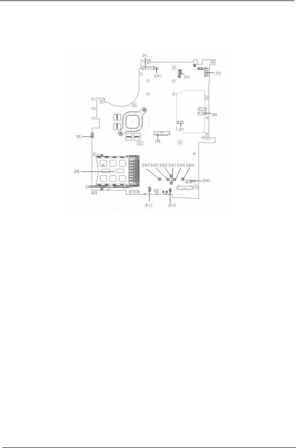
Board Layout
Top View
1 |
JP1 |
LCD Connector |
10 |
SW7 |
Touchpad Down Button |
2 |
SW1 |
Lid Switch |
11 |
SW2 |
Touchpad Up Button |
3 |
JP3 |
MDC Connector |
12 |
SW5 |
Touchpad Left Button |
4 |
JP2 |
Power Button Connector |
13 |
SW3 |
Touchapd Left Button |
5 |
JP6 |
Media Board Connector |
14 |
JP13 |
Internal Microphone Connector |
6 |
JP7 |
Touchpad Board Connector |
15 |
JP12 |
Internal Speaker Connector |
7 |
JP43 |
SIM Card Connector |
16 |
JP9 |
PCMCIA Socket |
8 |
SW4 |
Touchpad Right Button |
17 |
IR1 |
FIR Module |
9 |
SW6 |
Touchpad Left Button |
18 |
JP8 |
Internal Keyboard Connector |
4 |
Chapter 1 |
Bottom View
NOTE: This is engineering sample. The image above may not be exactly the same as the real main board you get.
1 |
JP19 |
FAN Connector |
17 |
JP40 |
Headphone/SPDIF Jack |
2 |
U42 |
VGA Chipset |
18 |
JP41 |
Line-In Jack |
3 |
JP18 |
CPU Socket |
19 |
JP42 |
Microphone-in Jack |
4 |
JP16 |
DVI Connector |
20 |
IR2 |
CIR Module |
5 |
JP15 |
CRT Connector |
21 |
SW8 |
Wireless LAN Switch |
6 |
JP14 |
TV-Out Connector |
22 |
SW9 |
Bluetooth and 3G Switch |
7 |
PCN1 |
DC-IN Jack |
23 |
U48 |
South Bridge Chipset |
8 |
JP17 |
Mini Card Connector |
24 |
JP30 |
Mini Card Connector |
9 |
JP22 |
DDRII so-DIMM Socket |
25 |
JP29 |
IEEE 1394 Connector |
10 |
JP21 |
DDRII so-DIMM Socket |
26 |
JP27 |
5 IN1 Socket |
11 |
J3 |
Clear CMOS Jumper |
27 |
JP23 |
RJ45 Connector |
12 |
JP24 |
ODD Connector |
28 |
JP5 |
USB Connector |
13 |
PJP1 |
Battery Connector |
29 |
JP4 |
USB Connector |
14 |
JP32 |
HDD Connector (SATA) |
30 |
JP28 |
MINIPCI Connector (TV-Tuner) |
15 |
JP33 |
HDD Connector (PATA) |
31 |
JP25 |
FAN Connector |
16 |
JP36 |
Bluetooth Connector |
32 |
U40 |
North Bridge Chipset |
Chapter 1 |
5 |
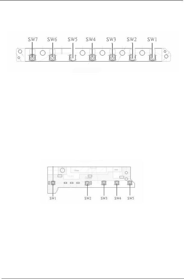
Jumper Board Layout
Switch Board Top View
Label |
Description |
|
|
SW1 |
Arcade/TV tunver switch |
|
|
SW2 |
Volume Up switch |
|
|
SW3 |
Volume Down switch |
|
|
SW4 |
Play/Pause switch |
|
|
SW5 |
Stop switch |
|
|
SW6 |
Forward/Next switch |
|
|
SW7 |
Backward/Previous switch |
|
|
Media Board Top View
Label |
Description |
|
|
SW1 |
Power Button |
|
|
SW2 |
E-mail Button |
|
|
SW3 |
Internet Button |
|
|
SW4 |
User Button |
|
|
SW5 |
E-Power Button |
|
|
6 |
Chapter 1 |
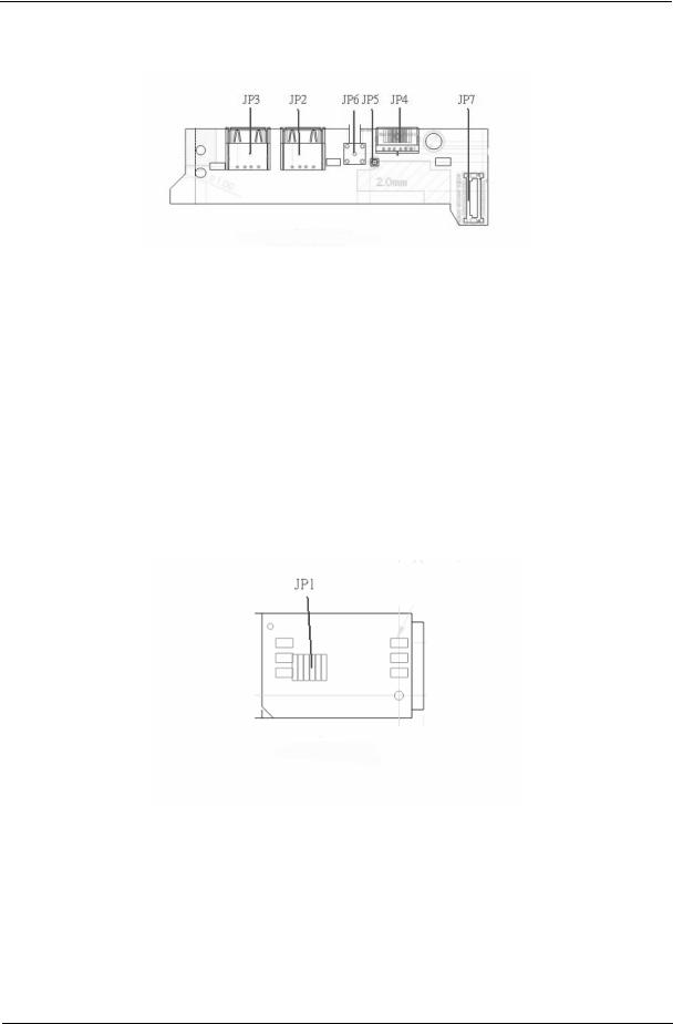
Media Board Bottom View
Label |
Description |
|
|
JP3 |
USB Connector |
|
|
JP2 |
USB Connector |
|
|
JP6 |
RF INe Connector |
|
|
JP5 |
RF Cable Connector |
|
|
JP4 |
AV IN Connector |
|
|
JP7 |
Board to Main Board |
|
Connector |
|
|
LS-2923P Power Board Top View
Label |
Description |
|
|
JP1 |
SIM Card Connector |
|
|
Chapter 1 |
7 |

Jumper Setting
Label |
Description |
|
|
J3 |
Clear CMOS Jumper |
|
Note: J3 locates at bottom |
|
side of the main board as |
|
the red circle highlighted. |
8 |
Chapter 1 |
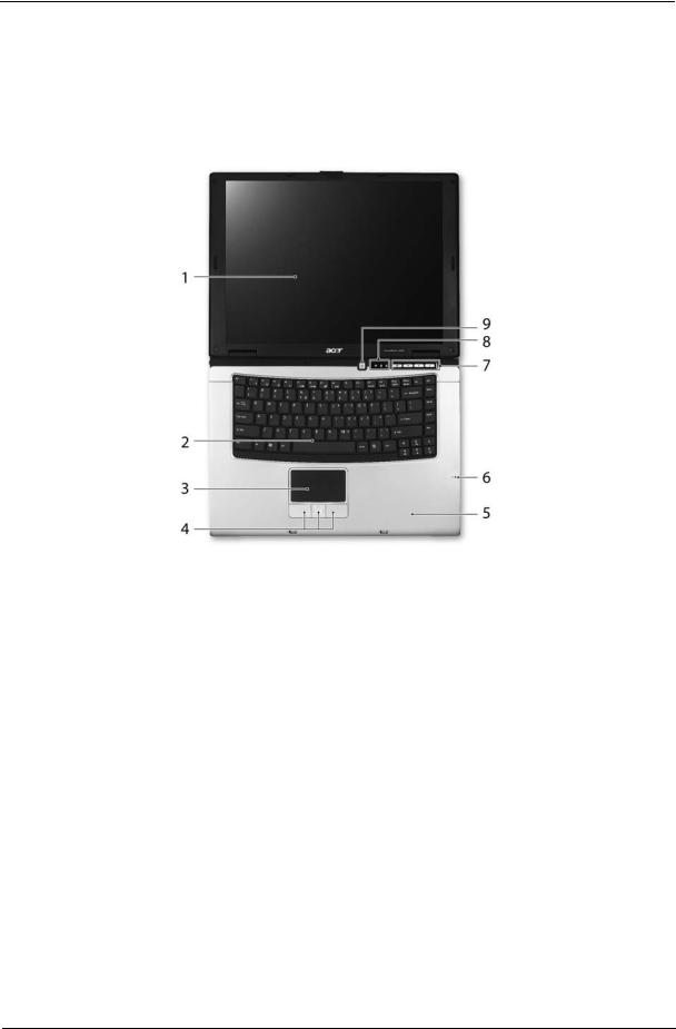
Your Acer Notebook tour
After knowing your computer features, let us show you around your new TravelMate computer.
TravelMate 4200 front view
# |
Icon |
Item |
Description |
|
|
|
|
1 |
|
Display screen |
Also called LCD (liquid-crystal display), |
|
|
|
displays computer output. |
|
|
|
|
2 |
|
Keyboard |
For entering data into your computer. |
|
|
|
|
3 |
|
Touchpad |
Touch-sensitive pointing device which |
|
|
|
functions like a computer mouse. |
|
|
|
|
4 |
|
Click buttons (left, |
The left and right buttons function like the |
|
|
center and right) |
left and right mouse buttons; the center |
|
|
|
button serves as a 4-way scroll button. |
|
|
|
|
5 |
|
Palmrest |
Comfortable support area for our hands |
|
|
|
when you use the computer. |
|
|
|
|
6 |
|
Microphone |
Internal microphone for sound recording. |
|
|
|
|
7 |
|
Easy-launch Buttons |
Buttons for launching frequently used |
|
|
|
programs. |
|
|
|
|
8 |
|
Status indicators |
Light-Emitting Diodes (LEDs) that light up |
|
|
|
to show the status of the computer’s |
|
|
|
functions and components. |
|
|
|
|
9 |
|
Power button |
Turns the computer on and off. |
|
|
|
|
Chapter 1 |
9 |
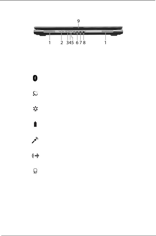
Closed Front View
# |
Icon |
Item |
Description |
||
|
|
|
|
|
|
1 |
|
|
|
Speaker |
Left and right speakers deliver stereo audio |
|
|
|
|
|
output. |
|
|
|
|
|
|
2 |
|
|
|
Bluetooth® |
Enable/disable Bluetooth function. |
|
|
|
|
communication button/ |
Indicates the status of Bluetooth- |
|
|
|
|
indicator |
communications. |
|
|
|
|
|
|
|
|
|
|
|
|
3 |
|
|
|
Wireless |
Enable/disable Wireless function. Indicates |
|
|
|
|
communication button/ |
the status of wireless LAN |
|
|
|
|
indicator |
communications. |
|
|
|
|
|
|
4 |
|
|
|
Power indicator |
Indicates the computer’s power status. |
|
|
|
|
|
|
5 |
|
|
|
Battery indicator |
Indicates the computer’s battery status. |
|
|
|
|
|
|
|
|
|
|
|
|
|
|
|
|
|
|
6 |
|
|
|
Microphone-in jack |
Accepts input from external microphones. |
|
|
|
|
|
|
7 |
|
|
|
Line-in jack |
Accepts audio line-in devices (e.g., audio |
|
|
|
|
|
CD player, stereo walkman). |
|
|
|
|
|
|
8 |
|
|
|
Headphones/ |
Connects to audio line-out devices (e.g., |
|
|
|
|
speakers/line-out jack |
speakers, headphones). |
|
|
|
|
with S/PDIF support |
|
|
|
|
|
|
|
9 |
|
|
|
Latch |
Locks and release the lid. |
|
|
|
|
|
|
10 |
Chapter 1 |
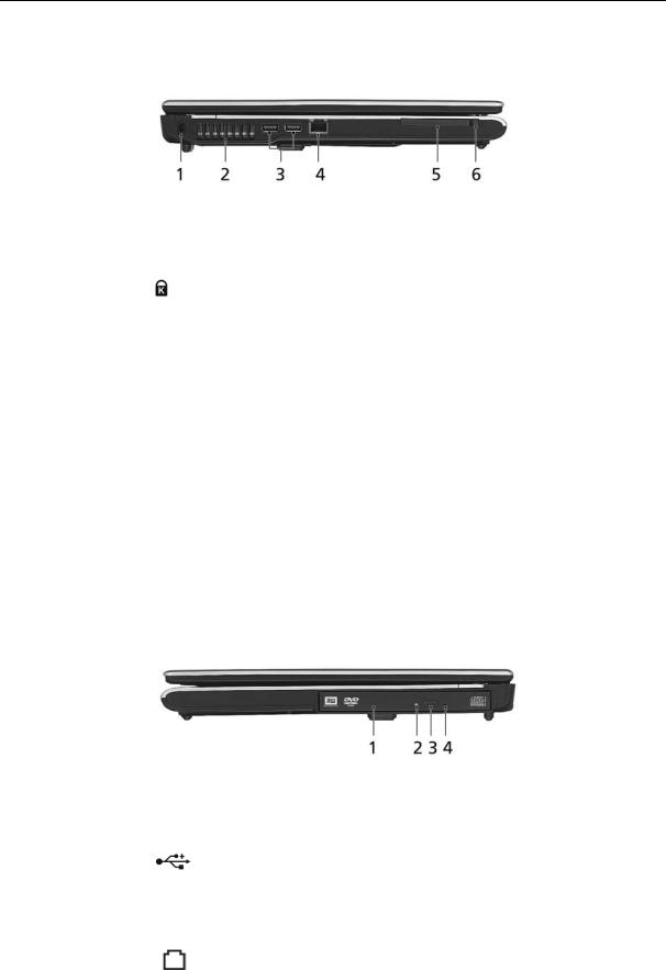
Left View
# |
Icon |
Item |
Description |
|||||
|
|
|
|
|
|
|
|
|
1 |
|
|
|
|
|
|
Kensington lock slot |
Connects to a Kensington-compatible |
|
|
|
|
|
|
|
|
computer security lock. |
|
|
|
|
|
|
|
|
|
2 |
|
|
|
|
|
|
Ventilation slots |
Enables the computer to stay cool, even |
|
|
|
|
|
|
|
|
after prolonged use. |
|
|
|
|
|
|
|
|
|
3 |
|
|
|
|
|
|
Two USB 2.0 ports |
Connects to USB 2.0 devices (e.g., USB |
|
|
|
|
|
|
|
|
mouse, USB camera). |
|
|
|
|
|
|
|
|
|
4 |
|
|
|
|
|
|
Modem (RJ-11) port |
Connects to a phone line. |
|
|
|
|
|
|
|
|
|
5 |
|
|
|
|
|
|
PC Card slot |
Accepts one Type II PC Card. |
|
|
|
|
|
|
|
|
|
|
|
|
|
|
|
|
|
|
|
|
|
|
|
|
|
|
|
|
|
|
|
|
|
|
|
|
6 |
|
|
|
|
|
|
PC Card slot eject |
Ejects the PC Card from the slot. |
|
|
|
|
|
|
|
button |
|
|
|
|
|
|
|
|
|
|
Right View
|
# |
Icon |
Item |
Description |
|
|
|
|
|
|
|
|
1 |
|
Three USB 2.0 ports |
Connect to USB 2.0 devices (e.g., USB |
|
|
|
|
|
mouse, USB camera). |
|
|
|
|
|
|
|
|
2 |
|
Ventilation slots |
Enable the computer to stay cool, even |
|
|
|
|
|
after prolong use. |
|
|
|
|
|
|
|
|
3 |
|
Modem (RJ-11) port |
Connects to a phone line. |
|
|
|
|
|
|
|
|
|
|
|
|
|
Chapter 1 |
11 |
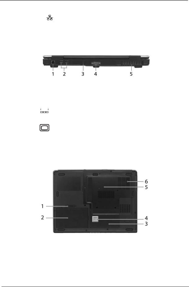
4 |
|
Ethernet (RJ-45) |
Connects to an Ethernet 10/100- |
|
|
|
based network. |
|
|
|
|
Rear Panel
# |
Icon |
Item |
Description |
||||||
|
|
|
|
|
|
|
|
|
|
1 |
|
|
|
|
|
|
|
DC-in jack |
Connects to an AC adapter. |
|
|
|
|
|
|
|
|
|
|
|
|
|
|
|
|
|
|
|
|
|
|
|
|
|
|
|
|
|
|
|
|
|
|
|
|
|
|
External display |
Connects to a display device(e.g., |
|
|
|
|
|
|
|
|
(VGA) port |
external monitor, LCD projector). |
|
|
|
|
|
|
|
|
|
|
|
|
|
|
|
|
|
|
Battery |
Powers the computer |
|
|
|
|
|
|
|
|
|
|
Base view
# |
Item |
Description |
|
|
|
1 |
Battery lock |
Locks the battery in position. |
|
|
|
2 |
Cooling fan |
Helps keep the computer cool. |
|
|
Note: Do not cover or obstruct the opening |
|
|
of the fan. |
|
|
|
3 |
Hard disk bay |
Houses the computer’s hard disk (secured |
|
|
with screws) |
|
|
|
12 |
Chapter 1 |
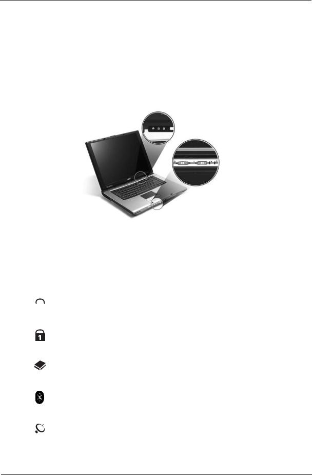
4 |
Memory compartment |
Houses the computer’s main memory. |
|
|
|
5 |
Battery release latch |
Release the battery for removal. |
|
|
|
6 |
Battery bay |
Houses the computer’s battery pack. |
|
|
|
Indicators
The computer has four easy-to-read status indicators on the upper-right above the keyboard, and four on the front panel.
TravelMate 4200:
The power, battery and wireless communication status indicators are visible even when the LCD display is closed.
Icon |
Function |
Description |
||
|
|
|
|
|
|
|
|
Cap lock |
Lights when Cap Lock is activated |
|
|
|
|
|
|
|
|
|
|
|
|
|
|
|
|
|
|
Num lock |
Lights when Num Lock is activated. |
|
|
|
|
|
|
|
|
HDD |
Indicates when the hard disc or optical |
|
|
|
|
drive is active. |
|
|
|
|
|
|
|
|
Bluetooth |
Indicates the status of Bluetooth |
|
|
|
|
communication. |
|
|
|
|
|
|
|
|
Wireless LAN |
Indicates the status of wireless LAN |
|
|
|
|
communication. |
|
|
|
|
|
Chapter 1 |
13 |
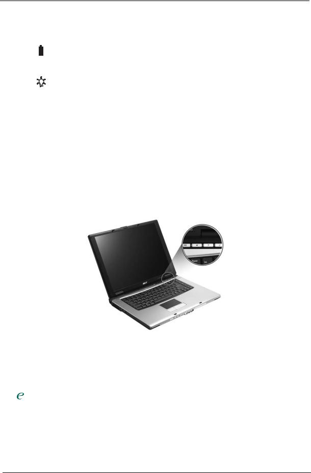
Icon |
Function |
Description |
||
|
|
|
|
|
|
|
|
Battery |
Lights up when the battery is being |
|
|
|
|
charged. |
|
|
|
|
|
|
|
|
|
|
|
|
|
Power |
Lights up when the computer is on. |
|
|
|
|
|
NOTE: 1. Charging: The light shows amber when the battery is charging. 2. Fully charged: The light shows green when in AC mode.
Easy-Launch Buttons
Located above the keyboard are four buttons. These buttons are called easy-launch buttons. They are: mail Web browser, Empowering Key “  “and one user-programmable button.
Press “  “ to run the Acer Empowering Technology. The mail and Web browser buttons are pre-set to email and Internet programs, but can be reset by users. To set the Web browser, mail and programmable buttons, run the Acer Launch Manager.
Launch key |
Default application |
|
|
P |
User-programmable |
|
|
P |
User-programmable |
|
|
|
Acer Empowering Technology (user-programmable) |
|
|
Web browser |
Internet browser (user-programmable) |
|
|
Email application (user-programmable) |
|
|
|
14 |
Chapter 1 |
Using the Keyboard
The keyboard has full-sized keys and an embedded keypad, separate cursor keys, two Windows keys and twelve function keys.
Lock Keys and embedded numeric keypad
The keyboard has three lock keys which you can toggle on and off.
Aspire Series:
TravelMate 4200:
Lock Key |
Description |
|
|
Caps Lock |
When Caps Lock is on, all alphabetic characters typed |
|
are in uppercase. |
|
|
Num lock |
When Num Lock is on, the embedded keypad is in |
<Fn>+<F11> |
numeric mode. The keys function as a calculator |
|
(complete with the arithmetic operators +, -, *, and /). |
|
Use this mode when you need to do a lot of numeric |
|
data entry. A better solution would be to connect an |
|
external keypad. |
|
|
Scroll lock |
When Scroll Lock is on, the screen moves one line up |
<Fn>+<F12> |
or down when you press the up or down arrow keys |
|
respectively. Scroll Lock does not work with some |
|
applications. |
|
|
The embedded numeric keypad functions like a desktop numeric keypad. It is indicated by small characters located on the upper right corner of the keycaps. To simplify the keyboard legend, cursor-control key symbols are not printed on the keys.
Desired Access |
Num Lock On |
Num Lock Off |
|
|
|
Number keys on embedded |
Type numbers in a normal |
|
keypad |
manner. |
|
|
|
|
Cursor-control keys on |
Hold <Shift> while using |
Hold <Fn> while using |
embedded keypad |
cursor-control keys. |
cursor-control keys. |
|
|
|
Chapter 1 |
15 |
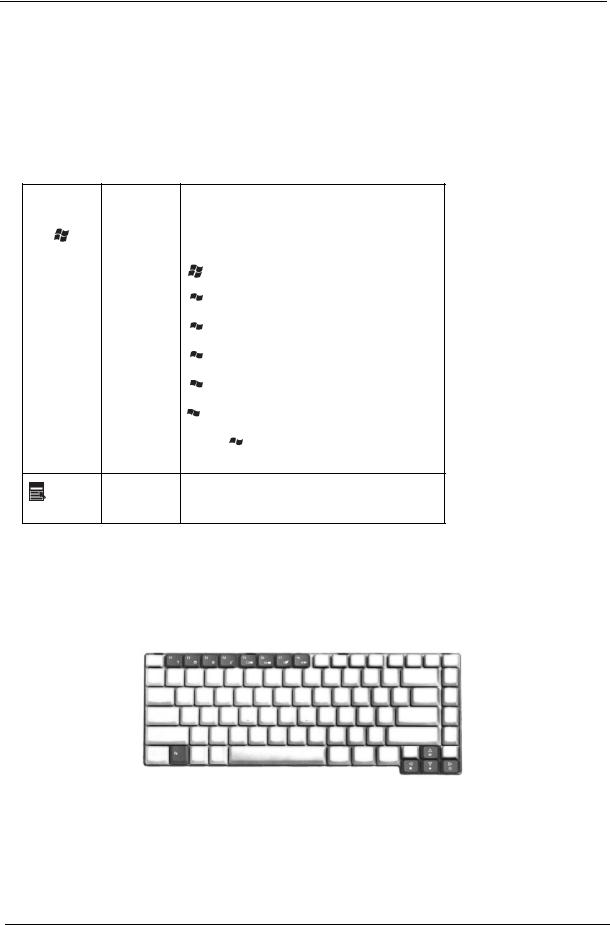
Desired Access |
Num Lock On |
Num Lock Off |
|
|
|
Main keyboard keys |
Hold <Fn> while typing |
Type the letters in a normal |
|
letters on embedded |
manner. |
|
keypad. |
|
|
|
|
Windows Keys
The keyboard has two keys that perform Windows-specific functions.
Key |
Icon |
Description |
|
|
|
Windows key |
|
Pressed alone, this key has the same effect as |
|
|
clicking on the Windows Start button; it launches the |
|
|
Start menu. It can also be used with other keys to |
|
|
provide a variety of function: |
+ <Tab> Activates next taskbar button.
 + <E> Opens the My Computer window
 + <F1> Opens Help and Support.
 + <F> Opens the Find: All Files dialog box.
 + <R> Opens the Run dialog box.
 + M Minimizes all windows.
<Shift>+  + <M> Undoes the minimize all windows action.
|
This key has the same effect as clicking the right |
|
Applicati |
mouse button; it opens the application’s context |
|
menu. |
||
on key |
||
|
Hot Keys
The computer employs hotkeys or key combinations to access most of the computer’s controls like sreen brightness, volume output and the BIOS utility.
To activate hot keys, press and hold the <Fn> key before pressing the other key in the hotkey combination.
Aspire Series:
TravelMate 4200:
16 |
Chapter 1 |
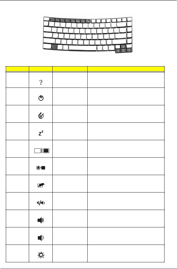
Hot Key |
Icon |
Function |
Description |
Fn-F1 |
|
Hot key help |
Displays help on hot keys. |
Fn-F2 |
|
Acer eSetting |
Launches the Acer eSettings in Acer eManager. |
Fn-F3 |
|
Acer |
Launches the Acer ePowerManagement in Acer |
|
|
ePowerManagement |
eManager. |
Fn-F4 |
|
Sleep |
Puts the computer in Sleep mode. |
Fn-F5 |
|
Display toggle |
Switches display output between the display screen, |
|
|
|
external monitor (if connected) and both. |
Fn-F6 |
|
Screen blank |
Turns the display screen backlight off to save power. |
|
|
|
Press any key to return. |
Fn-F7 |
|
Touchpad toggle |
Turns the internal touchpad on and off. |
Fn-F8 |
|
Speaker toggle |
Turns the speakers on and off. |
Fn-w |
|
Volume up |
Increases the speaker volume. |
Fn-y |
|
Volume down |
Decreases the speaker volume. |
Fn-x |
|
Brightness up |
Increases the screen brightness. |
Chapter 1 |
17 |
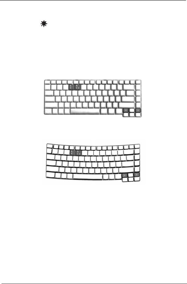
Hot Key |
Icon |
Function |
Description |
|
|
|
|
Fn-z |
|
Brightness down |
Decreases the screen brightness |
|
|
|
|
Special Key
You can locate the Euro symbol and US dollar sign at the upper-center and/or bottom-right of your keyboard. To type:
Aspire Series:
TravelMate 4200:
The Euro symbol
1.Open a text editor or word processor.
2.Either directly press the <Euro> symbol at the bottom-right of the keyboard, or hold <Alt Gr> and then press the<5> symbol at the upper-center of the keyboard.
The US dollar sign
1.Open a text editor or word processor.
2.Either directly press the <Dollar> key at the bottom-right of the keyboard, or hold <Shift> and then press the <4> key at the upper-center of the keyboard.
NOTE: This function varies by the operating system version.
NOTE: Some fonts and software do not support the Euro symbol. Please refer to www.microsoft.com/ typography/faq/faq12.htm for more information.
18 |
Chapter 1 |

Acer Empowering Technology
Acer’s innovative Empowering Technology makes it easy for you to access frequently used functions and manage your new Acer notebook. It features the following handy utilities:
Acer eDataSecurity Management protects data with passwords and advanced encryption algorithms. Acer eLock Management limits access to external storage media.
Acer ePerformance Management improves system performance by optimizing disk space, memory and registry settings.
Acer eRecovery Management backs up/recovers data flexibly, reliably and completely. Acer eSettings Management accesses system information and adjusts settings easily. Acer eNet Management hooks up to location-based networks intelligently.
Acer ePower Management extends battery power via versatile usage profiles.
Acer ePresentation Management connects to a projector and adjusts display settings conveniently.
For more information, press the <  > key to launch the Empowering Technology menu, then click on the appropriate utility and select the Help function.
Acer eDataSecurity Management
Acer eDataSecurity Management is handy file encryption utility that protexts your files from being accessed by unauthorized persons. It is conveniently integrated with Windows explorer as a shell extension for quick and
Chapter 1 |
19 |
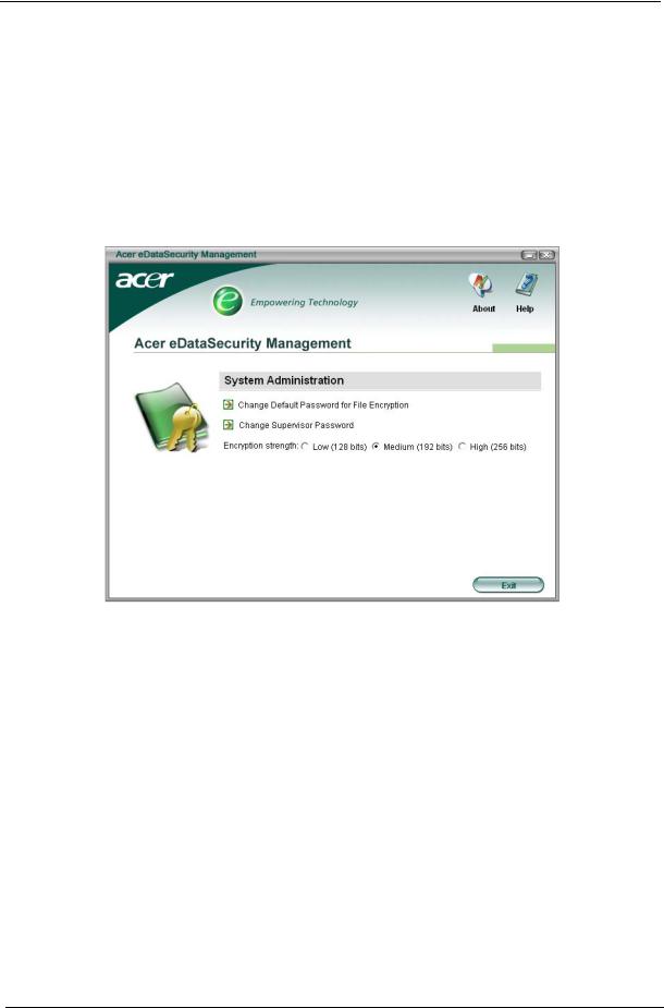
easy data encryption/decryption and also supports on-the-fly file encryption for MSN Messager and Microsoft Outlook.
There are two passwords that can be used to encrypt/decrypt a file; the supervisor passowrd and the filespecific password. The supervisor passwork is a “master” password that cna decrypt any file on your system; the file-specific password will be used to encrypt files by default, or you cna choose to enter your own filespecific password when encrypting a file.
NOTE: The password used encrypt a file is the unique key that the system needs to decrypt it. If you lose the password, the supervisor password is the only other key capable of decrypting the file. If you lose both passwords, there will be no way to decrypt your encryped file! Be sure to safeguard all related passwords!
20 |
Chapter 1 |
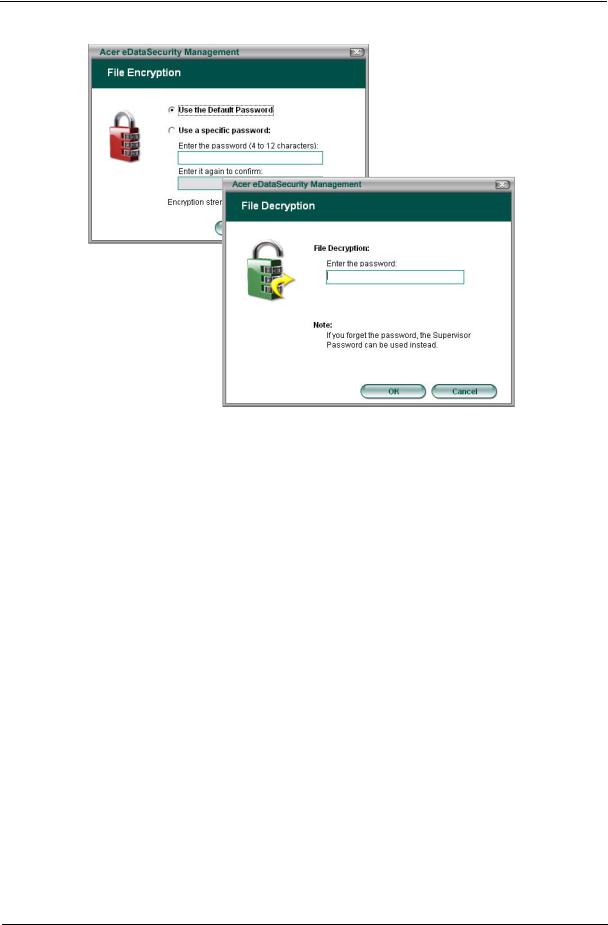
Acer eLock Management
Acer eLock Management is a security utility that allows you to lock up your removable data, optical and floppy drives to ensure that data can’t be stolen while your notebook is unattended.
Removable data devices - includes USB disk drives, USB pen drives, USB flash drives, USB MP3 drives, USB memory card readers, IEEE 1394 disk drives and any other removable disk drives that can be mounted as a file system when plugged into the system.
Optical drive deivces - includes any kind of CD-ROM or DVD-ROM drives. Floppy disk drives - 3.5-inch disks only.
To activate Acer eLock Management, a password must be set first. Once set, you may apply lock to any of the three kinds of devices. Lock(s) will immediately be set without any reboot necessary, and will remain locked after rebooting, until unlocked.
If you do not set a password, Acer eLock Management will reset back to the initial status with all locks removed.
NOTE: If you lose your password, there is no method to reset it except by reformatting your notebook or taking your notebook to anAcer Customer Serivce Center. Be sure to remember or write down your password.
Chapter 1 |
21 |
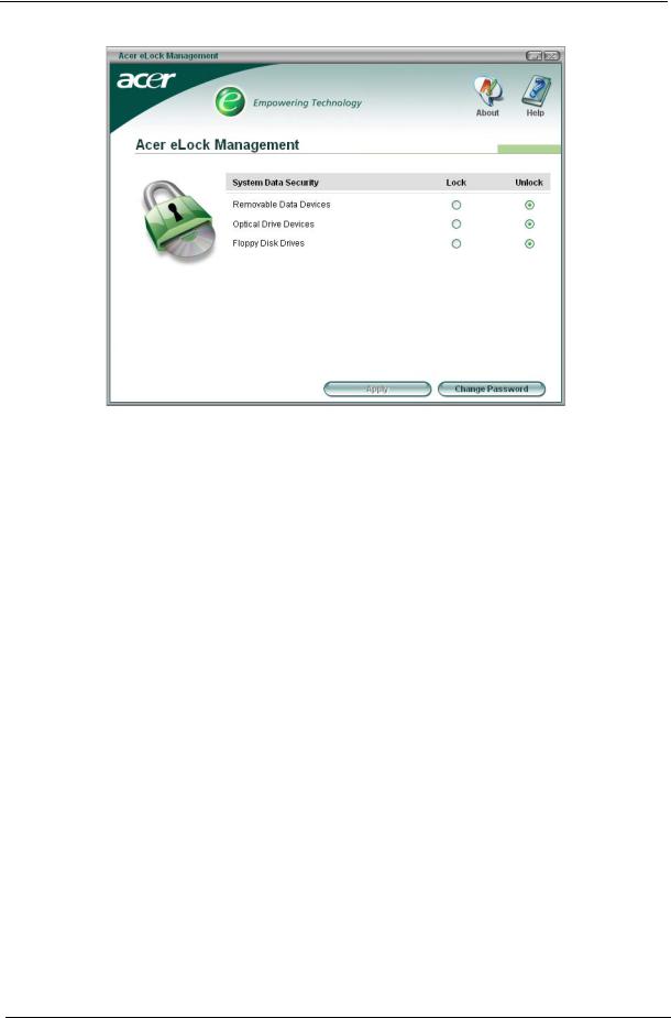
Acer ePerformance Management
Acer ePerformance Management is a system optimization tool that boosts the performance of your Acer notebook. It provides you with the following options to enhance overall system performance:
Memory optimization - releases unused memory and check usage. Disk optimization - removes unneeded items and files.
Speed optimization - improves the usability and performance of your Windows XP system.
22 |
Chapter 1 |

Acer eRecovery Management
Acer eRecovery Management is a powerful utility that does away with the need for recovery disks provided by the manufacturer. The Acer eRecovery Management utility occupies space in a hidden partition on your system’s HDD. User-created backups are stored on D:\ drive. Acer eRecovery Management provides you with:
Password protection.
Recovery of applications and drivers. Image/data backup:
Back up to HDD (set recovery point).
Back up to CD/DVD. Image/data recovery tools:
Recover from a hidden partition (factory defaults).
Recover from the HDD (most recent user-defined recovery point). Recover from CD/DVD.
Chapter 1 |
23 |
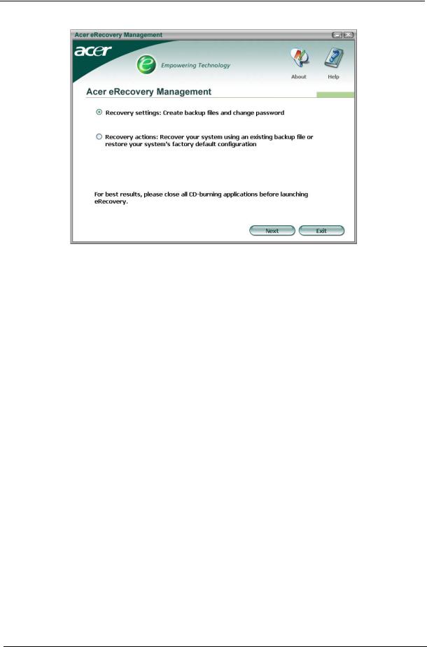
NOTE: If your computer did not come with a Recovery CD or System CD, please use Acer eRecovery Management’s “System backup to optical disk” feature to burn a backup image to CD or DVD. To ensure the best results when recovering your system using a CD or Acer eRecovery Management, detach all peripherals (except the external Acer ODD, if your computer has one), including your Acer ezDock.
Acer eSettings Management
Acer eSettings Management allows you to inspect hardware specifications and to monitor the system health status. Furthermore, Acer eSettings Management enables you to optimize your Windows operating system, so your computer runs faster, smoother and better.
Acer eSettings Management also:
Provides a simple graphical user interface for navigating through the program effortlessly. Displays general system status and advanced monitoring for power users.
Logs when a hardware component has been removed or replaced. Permits you to migrate personal settings.
Keeps a history log of all alerts that were previously issued.
24 |
Chapter 1 |
Loading...