


Maintenance Manual
Extensatm 450 Series
Notebook Computers
9805725-0001
November 1995

Copyright (©) 1995 Texas Instruments Incorporated
All Rights Reserved — Printed in U.S.A.
Extensa 450 Series Notebook Computers
Maintenance Manual
TI Part No. 9805725-0001
Original Issue: November 1995
Changes may be made periodically to the information in this publication. Such changes will be incorporated in new editions of this manual.
No part of this publication may be reproduced, stored in a retrieval system, or transmitted, in any form or by any means, electronic, mechanical, photocopy, recording, or otherwise, without the prior written permission of Texas Instruments Incorporated.
The equipment, as well as the programs that TI has created to use with them, are tools that can help people better manage the information used in their business; but tools — including TI products — cannot replace sound judgement nor make the manager’s business decisions.
Consequently, TI cannot warrant that its products are suitable for any specific customer application. The manager must rely on judgement of what is best for his or her business.
Address all correspondence regarding orders to:
Texas Instruments Incorporated
P.O. Box 6102, M/S 3255
Temple, Texas 76503
Extensa 450, TravelMate, 5000, 4000M, 4000E, 4000 and BatteryPro are trademarks of Texas Instruments Incorporated. The icons in the Windows Notebook and Startup groups are copyrighted by Texas Instruments Incorporated.
BitCom and BitFax are trademarks of BIT Software, Inc.
Hayes is a registered trademark and SmartModem2400 is a trademark of Hayes MicroComputer Products Inc.
IBM, OS/2, AT PS/2, and VGA are trademarks of International Business Machines Corporation.
Intel, and IntelDX4 are trademarks of Intel Corporation Lotus is a trademark of Lotus Development Corporation
MNP is a registered trademark and Microcom is trademark of Microcom Inc. Microsoft and Windows 95 are trade marks of Microsoft Corporation. Ethernet is a registered trademark of Xerox Corporation.
NetWare is a registered trademark of Novell, Inc.
UNIX is a registered trademark of American Telephone and Telegraph. SimulSCAN is a trademark of Cirrus Logic, Inc.

Contents
Preface
Section 1 General Description
1.1 Introduction. . . . . . . . . . . . . . . . . . . . . . . . . . . . . . . . . . . . 1-1
1.2 Product Models . . . . . . . . . . . . . . . . . . . . . . . . . . . . . . . . . 1-2
1.3 International Product Versions. . . . . . . . . . . . . . . . . . . . . . 1-2
1.4 Product Overview . . . . . . . . . . . . . . . . . . . . . . . . . . . . . . . . 1-3
1.4.1 External Ports . . . . . . . . . . . . . . . . . . . . . . . . . . . . . . 1-5
1.4.2 Touchpad Pointing Device . . . . . . . . . . . . . . . . . . . . . 1-6
1.4.3 Keyboard . . . . . . . . . . . . . . . . . . . . . . . . . . . . . . . . . 1-6
1.4.4 Standard Power Features. . . . . . . . . . . . . . . . . . . . . . 1-8
1.4.5 Wireless Connection With Serial Infrared Port . . . . . . 1-9
1.4.6 Preloaded Software . . . . . . . . . . . . . . . . . . . . . . . . . . 1-9
1.4.7 Notebook Expansion Capabilities . . . . . . . . . . . . . . . . 1-9
1.5 Standard Test Features . . . . . . . . . . . . . . . . . . . . . . . . . . . 1-10
1.6 Notebook Assemblies and Subassemblies. . . . . . . . . . . . . . 1-10
1.6.1 Cover-Display Assembly . . . . . . . . . . . . . . . . . . . . . . 1-11
1.6.2 System Base Assembly . . . . . . . . . . . . . . . . . . . . . . . 1-11
1.7 Extensa 450 Series Notebook Specifications. . . . . . . . . . . . 1-12
1.8 Agency Approvals. . . . . . . . . . . . . . . . . . . . . . . . . . . . . . . . 1-13
Section 2 Installation
2.1 Introduction. . . . . . . . . . . . . . . . . . . . . . . . . . . . . . . . . . . . 2-1
2.2 Unpacking Instructions . . . . . . . . . . . . . . . . . . . . . . . . . . . 2-1
2.3 Installing Notebook Options . . . . . . . . . . . . . . . . . . . . . . . 2-1
2.3.1 Installing Dual Inline Memory Module(s) . . . . . . . . . . 2-1
2.3.2 Installing PCMCIA Options. . . . . . . . . . . . . . . . . . . . . 2-3
2.3.3 Installing the Port Adapter . . . . . . . . . . . . . . . . . . . . 2-4
2.3.4 Installing the Optional Numeric Keypad . . . . . . . . . . 2-5
2.4 Installing the Battery Pack(s ) . . . . . . . . . . . . . . . . . . . . . . . 2-5
2.5 Installing External Devices . . . . . . . . . . . . . . . . . . . . . . . . . 2-6
Contents iii

2.5.1 Installing an External Keyboard/Mouse . . . . . . . . . . . 2-6
2.5.2 Installing External Parallel Printer . . . . . . . . . . . . . . . 2-8
2.5.3 Installing External Serial Port Device . . . . . . . . . . . . . 2-8
2.5.4 Installing External VGA Monitor . . . . . . . . . . . . . . . . . 2-10
2.5.5 Installing SIR Devices . . . . . . . . . . . . . . . . . . . . . . . . . 2-10
2.6 Installing the AC Power Adapter . . . . . . . . . . . . . . . . . . . . 2-11
2.7 Initial System Checkout . . . . . . . . . . . . . . . . . . . . . . . . . . . 2-12
2.8 Configuring the System. . . . . . . . . . . . . . . . . . . . . . . . . . . . 2-12
2.9 Making Backups of System Software. . . . . . . . . . . . . . . . . . 2-13
2.10 Loading Application Software . . . . . . . . . . . . . . . . . . . . . . 2-13
Section 3 Operating Instructions
3.1 Introduction . . . . . . . . . . . . . . . . . . . . . . . . . . . . . . . . . . . . 3-1 3.2 Notebook Controls and Indicators . . . . . . . . . . . . . . . . . . . . 3-1 3.2.1 LCD Brightness Control . . . . . . . . . . . . . . . . . . . . . . . 3-2 3.2.2 Button Switches . . . . . . . . . . . . . . . . . . . . . . . . . . . . . 3-2 3.2.3 Cover Release Latch . . . . . . . . . . . . . . . . . . . . . . . . . . 3-3 3.2.4 Touch Pad Controls . . . . . . . . . . . . . . . . . . . . . . . . . . 3-3 3.2.5 Keyboard Mode LEDs. . . . . . . . . . . . . . . . . . . . . . . . . 3-3 3.3 Operating Procedures . . . . . . . . . . . . . . . . . . . . . . . . . . . . 3-3 3.3.1 Floppy Drive Operating Procedures . . . . . . . . . . . . . . 3-4 3.3.2 Installing/Removing PCMCIA Options . . . . . . . . . . . . 3-4 3.3.3 Computer Hot Keys . . . . . . . . . . . . . . . . . . . . . . . . . . 3-5 3.3.4 Responding to Low Battery Conditions. . . . . . . . . . . . 3-5 3.3.5 Minimizing Power Usage . . . . . . . . . . . . . . . . . . . . . . 3-5 3.3.6 Recharging the Battery Packs . . . . . . . . . . . . . . . . . . 3-6 3.3.7 Restoring Missing System Files . . . . . . . . . . . . . . . . . 3-6 3.3.8 Rebuilding the System Software. . . . . . . . . . . . . . . . . 3-6
Section 4 Theory of Operation
4.1 Introduction . . . . . . . . . . . . . . . . . . . . . . . . . . . . . . . . . . . . 4-1
4.2 Notebook Functional Description . . . . . . . . . . . . . . . . . . . . 4-1
4.2.1 Processor/Memory Subsystems . . . . . . . . . . . . . . . . 4-1
4.2.2 I/O Subsystem . . . . . . . . . . . . . . . . . . . . . . . . . . . . . 4-6
4.2.3 Video Subsystem . . . . . . . . . . . . . . . . . . . . . . . . . . . . 4-7
iv Contents

4.2.4 Hard Disk Subsystem . . . . . . . . . . . . . . . . . . . . . . . . 4-8
4.2.5 Floppy Diskette Drive Subsystem. . . . . . . . . . . . . . . . 4-9
4.2.6 PCMCIA Subsystem . . . . . . . . . . . . . . . . . . . . . . . . . . 4-9
4.2.7 Power Subsystem. . . . . . . . . . . . . . . . . . . . . . . . . . . . 4-10
Section 5 Troubleshooting Procedures
5.1 General . . . . . . . . . . . . . . . . . . . . . . . . . . . . . . . . . . . . . . . 5-1
5.2 Overview of Fault Isolation Process . . . . . . . . . . . . . . . . . . 5-1
5.3 Troubleshooting Procedures. . . . . . . . . . . . . . . . . . . . . . . . 5-3
5.3.1 Troubleshooting a Power Supply Problem . . . . . . . . . 5-3
5.3.2 Troubleshooting a Display Problem . . . . . . . . . . . . . . 5-5
5.3.3 Fault Isolation Using Selftest . . . . . . . . . . . . . . . . . . . 5-5
5.3.4 PCMCIA Modem Problems. . . . . . . . . . . . . . . . . . . . . . 5-5
5.3.5 Fault Isolation Using Diagnostics . . . . . . . . . . . . . . . . 5-6
Section 6 Field Service
6.1 Introduction . . . . . . . . . . . . . . . . . . . . . . . . . . . . . . . . . . . . 6-1
6.2 Preventive Maintenance . . . . . . . . . . . . . . . . . . . . . . . . . . . 6-1
6.2.1 Cleaning the Computer . . . . . . . . . . . . . . . . . . . . . . . 6-1
6.2.2 Protecting the Disk Drives . . . . . . . . . . . . . . . . . . . . . 6-2
6.2.3 Handling the Computer Battery Pack. . . . . . . . . . . . . 6-2
6.2.4 Restoring System Software. . . . . . . . . . . . . . . . . . . . . 6-2
6.3 Required Tools and Equipment . . . . . . . . . . . . . . . . . . . . . 6-3
6.4 Notebook Field-Replaceable Parts and Assemblies. . . . . . . . 6-3
6.4.1 Cover-Display Assembly . . . . . . . . . . . . . . . . . . . . . . 6-3
6.4.2 System Base Assembly . . . . . . . . . . . . . . . . . . . . . . . 6-4
6.5 FRU Removal and Replacement Procedures . . . . . . . . . . . . 6-6
6.5.1 Removing/Replacing the Notebook Battery Pack . . . . . 6-6
6.5.2 Removing/Replacing PCMCIA Options . . . . . . . . . . . . 6-7
6.5.3 Removing/Replacing the Floppy Drive . . . . . . . . . . . . 6-7
6.5.4 Removing/Replacing the Hard Drive . . . . . . . . . . . . . 6-7
6.5.5 Removing/Replacing the Keyboard Assembly . . . . . . . 6-8
6.5.6 Removing/Replacing the Heat Sink . . . . . . . . . . . . . . 6-8
6.5.7Removing/Replacing Memory Modules (DIMMS) . . . . 6-9
6.5.8Removing and Replacing the Cover-Display Assembly 6-10
Contents v

6.5.9 Removing and Replacing the Inverter Board. . . . . . . . 6-10 6.5.10 Opening/Replacing the Top Case Assembly . . . . . . . 6-11 6.5.11 Removing/Replacing the Touch Pad Assembly . . . . . 6-11 6.5.12 Removing/Replacing the SIR Board . . . . . . . . . . . . . 6-13 6.5.13 Removing/Replacing the Primary Battery Board . . . 6-14 6.5.14 Removing/Replacing Power Supply Board . . . . . . . . 6-15 6.5.15 Removing/Replacing the Memory Board . . . . . . . . . 6-16 6.5.16 Removing/Replacing the Main Board . . . . . . . . . . . . 6-16 6.5.17 Removing/Replacing the Secondary Battery Board . 6-18
Appendix A Self-Test Error Messages
A.1 Introduction . . . . . . . . . . . . . . . . . . . . . . . . . . . . . . |
A-1 |
Appendix B Connector Pinouts
B.1 Introduction . . . . . . . . . . . . . . . . . . . . . . . . . . . . . . . . . . . B-1
Appendix C PC-Doctor Diagnostics
C.1 Introduction . . . . . . . . . . . . . . . . . . . . . . . . . . . . . . . . . . . C-1
C.2 Starting PC-Doctor . . . . . . . . . . . . . . . . . . . . . . . . . . . . . . C-1
C.3 Keyboard Navigation . . . . . . . . . . . . . . . . . . . . . . . . . . . . . C-2
C.4 Mouse Navigation . . . . . . . . . . . . . . . . . . . . . . . . . . . . . . . C-2
C.5 PC-Doctor Menus . . . . . . . . . . . . . . . . . . . . . . . . . . . . . . . C-3
C.5.1 Online Help (?). . . . . . . . . . . . . . . . . . . . . . . . . . . . . . C-3
C.5.2 Diagnostics . . . . . . . . . . . . . . . . . . . . . . . . . . . . . . . . C-3
C.5.3 Interactive Tests Menu . . . . . . . . . . . . . . . . . . . . . . . C-4
C.5.4 Hardware Info Menu . . . . . . . . . . . . . . . . . . . . . . . . . C-5
C.5.5 Utility Menu . . . . . . . . . . . . . . . . . . . . . . . . . . . . . . . C-5
C.6 Quitting PC-Doctor . . . . . . . . . . . . . . . . . . . . . . . . . . . . . . C-6
C.7 Remote Operation . . . . . . . . . . . . . . . . . . . . . . . . . . . . . . . C-6
vi Contents

Preface
This manual provides installation, operation and servicing data for the Extensatm 450 Series Notebook Computers.
Intended Audience
This manual is primarily intended for use by qualified service technicians but contains information useful to non-technical users.
Contents
This manual contains six sections and multiple reference appendices including:
∙ Section 1: General Description — Introduces the main features of the notebook; provides a list of physical and electrical specifications.
∙ Section 2: Installation — Describes how to unpack, install options and cable up the notebook computer in a desktop environment.
∙ Section 3: Operating Instructions — Describes the notebook operating controls and indicators and modes of operation.
∙ Section 4: Theory of Operation — Describes detailed theory of operation for Extensa series notebooks.
∙ Section 5: Troubleshooting — Provides troubleshooting procedures for the Extensa 450 series notebooks.
∙ Section 6: Field Service — Provides corrective maintenance
|
procedures for the notebook computer. |
|
∙ Appendix A: Self Test Error Messages |
|
∙ Appendix B: Connector Pinouts |
|
∙ Appendix C: PC-Doctor Reference Data |
n |
|
Note: Additional appendices will be added at a future date to document |
|
new members of the Extensa product family. |
|
|
|
|
Other Manuals About the System |
|
The following documents provide additional information related to the |
|
Extensa 450 series: |
Preface vii

∙Extensa 450 Series Notebook Computer User’s Reference Manual,
Part No. 9803942-0001; contains reference information regarding the Extensa 450 series software including the TI custom utilities.
∙Windows 95 Help (online)
∙PC-Doctor Help and Technical Reference (online)
Ordering Parts and Supplies
To order a copy of any TI publication or to order option kits, spare parts or supplies for your system, contact your TI Reseller or:
Telephone Toll-free: 1-800-TI TEXAS
viii Preface
Section 1
General Description
1.1Introduction
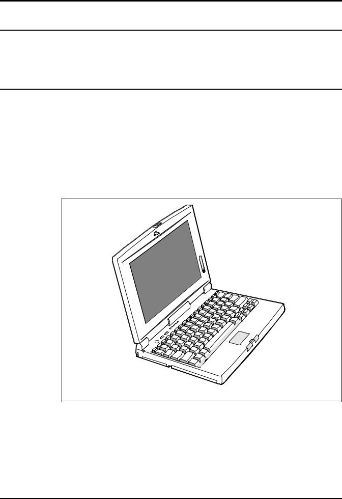
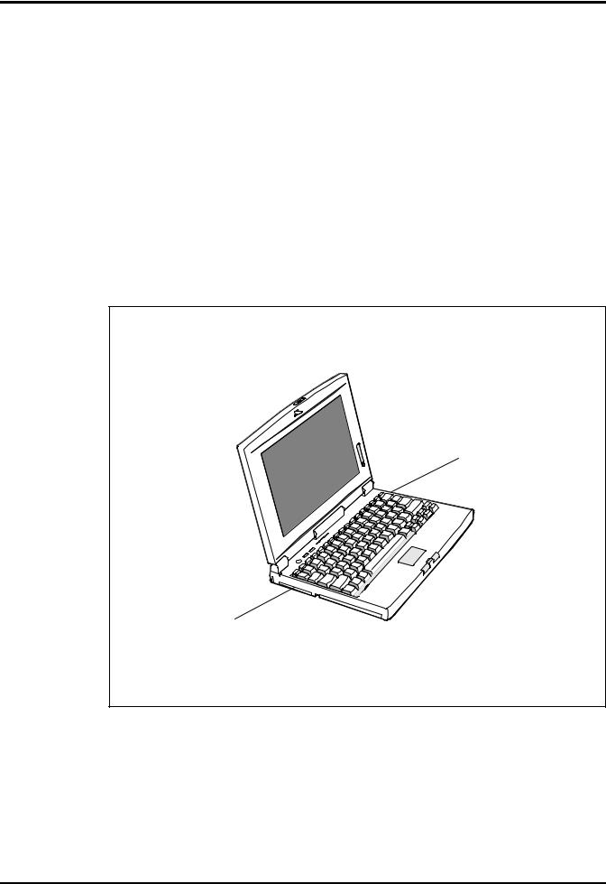
This manual contains field and factory level servicing information for the Texas Instruments Extensa tm 450 Series of Notebook Computers (Figure 1-1).
This section provides a general overview and specifications for the Extensa 450 Series Notebook Computers.
Figure1-1 Extensa 450 Series Notebook Computer
General Description 1-1

1.2Product Models
Table 1-1 summarizes the features of the product models initially available in the Extensa 450 product line. Basically, the product models offer a choice of either 10.4" Dual Scan Color or 9.4" Active Matrix Color LCDs and a choice of either the basic Windows 95 operating system or Windows 95 plus applications.
Table 1-1 Extensa 450 Series Notebook Computers
Model 450 |
Model 450T |
Model 455 |
Model 455T |
|
|
|
|
10.4" DS LCD |
9.4" Active Matrix |
10.4" DS LCD |
9.4" Active Matrix |
|
Color |
|
Color |
|
|
|
|
Windows 95 |
Windows 95 |
Windows 95 Plus |
Windows 95 Plus |
|
|
Microsoft Works, |
Microsoft Works, |
|
|
Quicken SE, |
Quicken SE, |
|
|
Lotus Organizer, |
Lotus Organizer, |
|
|
and Microsoft |
and Microsoft |
|
|
Entertainment |
Entertainment |
|
|
Pack |
Pack |
|
|
|
|
|
|
|
|
1.3International Product Versions
The Extensa 450 Series Notebooks are available in one of 15 domestic and international configurations as listed in Table 1-2.
Table 1-2. Notebook Domestic/International Configurations
Configuration |
P/N Suffix |
Configuration |
P/N Suffix |
|
|
|
|
Domestic |
-0001 |
Swedish |
-0010 |
|
|
|
|
UK |
-0002 |
Swiss/French |
-0011 |
|
|
|
|
German |
-0003 |
Danish |
-0012 |
|
|
|
|
French |
-0004 |
Norwegian |
-0013 |
|
|
|
|
Spanish |
-0005 |
Finish |
-0014 |
|
|
|
|
Swiss/German |
-0006 |
Belgium |
-0015 |
|
|
|
|
Italian |
-0007 |
Austrian |
-0016 |
|
|
|
|
Portuguese |
-0008 |
Latin American |
-0018 |
|
|
|
|
Western European |
-0009 |
|
|
|
|
|
|
|
|
|
|
1-2 General Description
1.4Product Overview
All members of the Extensa 450 Series are high performance notebooks powered by the 75MHz IntelDX4 processor and Windows 95 tm Operating System software.
As a standard feature, all members of the Extensa 450 family also contain the following features:
∙4MB of RAM memory (user-expandable to 32MB)
∙128 bytes of battery-backed up CMOS RAM
∙512 KB of video RAM
∙340 Million Byte Hard Drive (user replaceable)
∙Support for one PCMCIA Type I or II option (Type III if floppy drive is removed with option)
∙Ergonomic keyboard with palm rest (2.7 mm travel); built-in touchpad pointing device
∙Most standard external device interfaces including serial, parallel, PS/2, external VGA, and serial infrared wireless port
∙Removable 3.5", 1.44 MB Floppy Drive (second Lithium Ion battery or a type III PCMCIA device can be installed in its place with option)
∙Choice of LCD displays (10.4" Dual Scan Color or 9.4" Active Matrix Color LCD).
∙AC Adapter with autosensing (100 VAC to 240 VAC, 50 to 60 Hz); 34 Watts of DC output power
∙10.8 Volt, 2400 mAH capacity, Nickel-Metal Hydride (NiMH) primary battery pack
∙Provisions for secondary 10.8V, 1460 mAH capacity, Lithium-Ion Battery Pack (with removal of Floppy Drive)
∙Power management features for longer portable operation away from AC power.
General Description 1-3

Figure 1-2 Extensa 450 Series Features
1-4 General Description
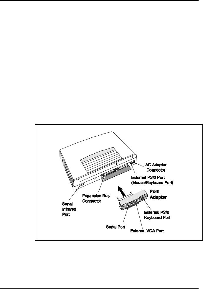
1.4.1External Ports
As shown in Figure 1-3, the notebook computer contains the following external ports:
∙Serial Infrared (SIR) Port for wireless connection with a similarly equipped printer or computer
∙9-Pin Serial Port for attaching any RS-232 type serial device to the Notebook
∙15-Pin External VGA Monitor Port for attaching an external monitor
∙6-Pin PS/2 Port to attach an external Keyboard or Mouse
∙Second 6-Pin PS/2 Port for attaching an external Keyboard/Mouse
∙AC Adapter Connector for attaching the AC Adapter to the notebook
Figure 1-3 Notebook External Ports
General Description 1-5
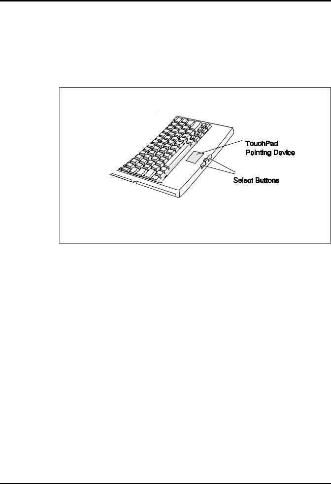
1.4.2Touchpad Pointing Device
All members of the Extensa family feature a built-in Touchpad pointing device located near the center of the keyboard’s palmrest. With light presure, the cursor can quickly be positioned to the desired point; a quick double tap on the Touchpad and you have selected an object. Two select buttons (switches) are located along the front edge of the notebook
.
Figure1-4 Extensa Touchpad
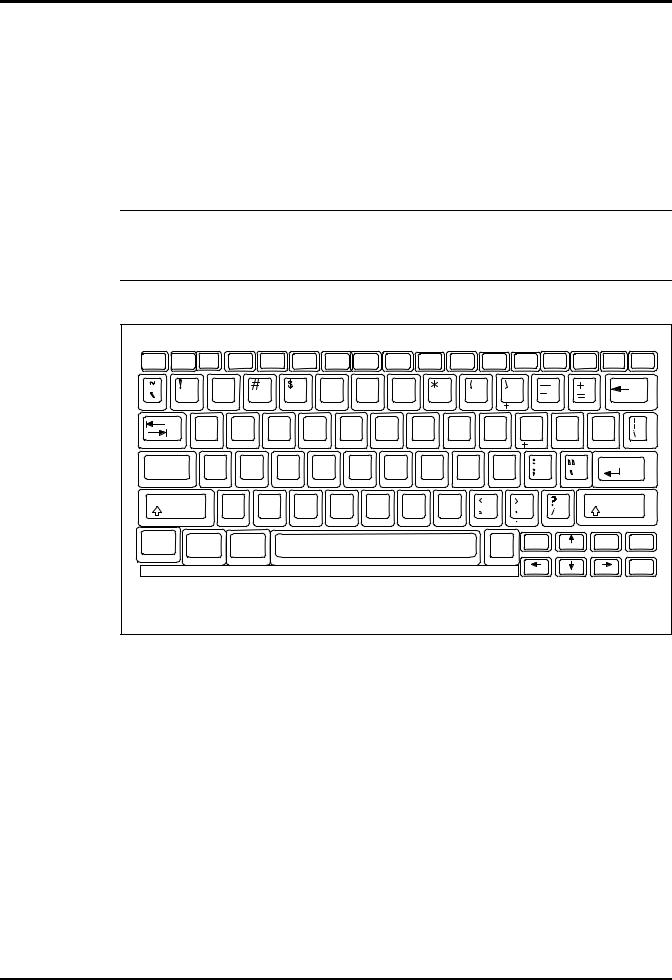
1.4.3Keyboard
The Extensa Series Keyboard is an 83/84-key, IBM enhanced-type keyboard with the standard character and function keys plus 12 programmable function keys (F1 through F12).
Using the Special Function (Fn) key which assigns multiple functions to keys, the keyboard can emulate the IBM 101/102 keyboards using 83 keys (84 on international models).
The keyboard has a 2.77 mm stroke and features a special keyboard interface chip that can detect multiple levels of key input (good simulation of N-key rollover for up to 10 keys).
Some of the major features of the keyboard include:
∙
∙
∙
2.77-mm Key movement
Integrated numeric keypad
“Inverted T" Cursor Control Key layout
1-6 General Description
The notebook keyboard is available in the following versions:
∙U.S. English - This version (also known as the domestic version) has 81 keys and is generally used in the United States and Canada.
∙U.K. English - This version (also known as the international version) has 82 keys and is generally used in England, Germany, and other European countries with the appropriate keycap changes.
nNote: The Extensa Series Notebook Computer User’s Reference Manual contains descriptions of keyboard special function keys. A six-pin Mini-DIN connector can attach to either an external PS/2 keyboard (or 101 Keyboard via an adapter), PS/2 Mouse, or the optional PS/2 Numeric Keypad.
-I? |
. . |
.! |
F4 |
|
.# |
.$ |
.% |
|
.& |
.' |
. |
F11 |
|
F12 |
NumLk |
Prt Sc |
Insert |
Delete |
|
|
|
Pause |
Break |
ScrLk |
SysRq |
||||||||||||||
|
|
|
|
|
|
|
|
|
|
|
|
|
|
|
|||||
|
|
|
|
|
|
|
|
|
|
|
|
|
|
|
|
|
|||
|
|
@ |
|
|
|
|
|
^ |
|
& |
|
|
|
|
|
|
|
|
|
|
|
2 |
|
|
|
|
|
|
7 |
& |
|
9 |
|
|
|
|
|
|
|
|
1 |
|
3 |
|
4 |
5 |
6 |
|
|
|
|
|
|
|
|||||
|
|
|
|
|
|
|
|
|
|
% |
& |
|
' |
|
|
|
|
|
|
|
|
Q |
9 E |
|
R |
|
6 |
; |
U |
|
1 |
O |
|
P |
{ |
|
} |
|
|
|
|
|
|
|
|
|
|
|
|
|
|
|
|
|
|
[ |
|
] |
|
|
|
|
|
|
|
|
|
|
|
" |
|
# |
$ |
|
|
|
|
|
|
Caps |
|
A |
S |
|
D |
F |
|
G |
|
H |
J |
K |
L |
|
|
|
|
Enter |
|
Lock |
|
|
|
|
|
|
|
|
|
|
|
|
|
|
|
|
|
|
|
|
|
|
|
|
|
|
|
|
|
|
|
|
! |
|
|
|
|
|
|
Shift |
|
|
Z |
: |
|
C |
V |
|
B |
N |
|
M |
|
|
|
|
Shift |
|
|
|
|
|
|
|
|
|
|
|
|
|
|
|
|
|
|
|
|
|
|
Fn |
|
Ctrl |
Alt |
|
|
|
|
|
|
|
|
|
Alt |
|
Home |
|
End |
2C7p |
|
|
|
|
|
|
|
|
|
|
|
|
|
|
|
|
|
|
|||
|
|
|
|
|
|
|
|
|
|
|
|
|
|
|
|
|
|
|
2C,n |
|
|
|
|
|
Figure1-5 |
Extensa Keyboard |
|
|
|
|
|
||||||||
1.4.3.1Controls and Indicators
As shown in Figure 1-6, Extensa Series Notebook Computers contain a set of three buttons (switches) and five LED displays just above the keyboard including:
∙Power, Setup, and Standby/Suspend Buttons (Switches)
∙Caps Lock indicator. This LED indicates that the keyboard is locked in the uppercase mode. To switch to the lowercase mode, press the Caps Lock key.
∙Num Lock indicator. This LED lights when you press the NumLk key to toggle on the numeric keypad lock function. When the LED is On, the embedded numeric keyboard keys generate AT-keypad characters and functions when pressed in conjunction with the Shift key. When the indicator is Off, pressing
General Description 1-7
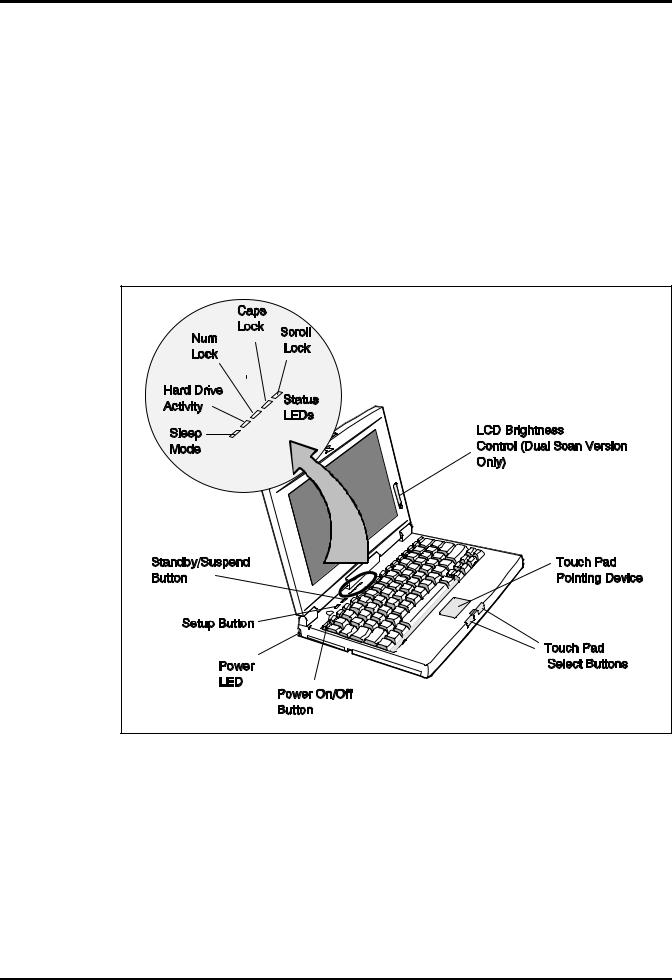
the Fn key with the appropriate keys provides cursor movement, paging and other functions in the normal mode.
∙Scroll Lock indicator. This LED lights to indicate that the keyboard is locked in the scroll mode.
∙Hard Disk Drive Activity Indicator. Indicates when notebook is accessing the hard drive.
∙Standby Indicator. Lights when Notebook is in Standby mode.
Figure1-6 Extensa Series Controls and Indicators
1.4.4Standard Power Features
Notebook power for the Extensa 450 Series Notebook Computers is provided by an AC Adapter and a rechargeable 10.8 V, 2400 mAh Duracell nickel metal hydride (NiMH) battery pack that installs in a power bay near the front of the notebook (right side).
A second lithium ion battery may optionally be installed in the Floppy Drive bay when the Floppy Drive is removed from the Notebook.
1-8 General Description

All members of the Extensa 450 family feature TI’s patented power management subsystem (hardware and software) that provides longer portable operation and protection of files during low battery conditions.
1.4.5Wireless Connection With Serial Infrared Port
The Extensa series notebooks are equipped with a Serial Infrared (IR) port that offers wireless communication with a variety of IRDA-compliant devices made by other manufacturers.
nNote: Prior to communicating with an external device equipped with a serial infrared interface, the appropriate third-party drivers must be installed on your notebook.
1.4.6Preloaded Software
All members of the Extensa 450 Notebook family are preloaded with the Windows 95 Operating System. In addition, Extensa Models 455 and 455T come standard with the following application packages installed:
∙
∙
∙
∙
Microsoft Works
Quicken SE
Lotus Organizer
Microsoft Entertainment Pack No. 4
1.4.7Notebook Expansion Capabilities
Expansion capabilities built into the Extensa notebook series include:
∙User installable expansion RAM memory (to a maximum of 32 MB)
∙By removing the floppy drive, you can add either a second battery pack or a Type III PCMCIA device with option.
∙A Cable Connect PS/2 Numeric Keypad option, P/N 2581381-0001, can be attached to either of the two external PS/2 Ports.
∙A parallel device can be attached to the notebook’s external 25-pin parallel port (EPP/ECP compatible).
∙With the port adapter installed (supplied with the notebook), the notebook’s expansion bus is adapted to provide the following external ports:
–Serial RS-232 Port for attaching any serial device
–External VGA Port for driving an external color monitor
–Second PS/2 Port for attaching an external keyboard or mouse
General Description 1-9
∙Third Party External PS/2 keyboard (or external mouse)
1.5Standard Test Features
The Extensa Series Notebook Computers use modular design and built-in test features to reduce the mean time to repair. A power on self-test automatically verifies the operational state of the primary circuits and a powerful suite of diagnostic tests are available to further test selected parts of the system.
1.6 Notebook Assemblies and
Subassemblies
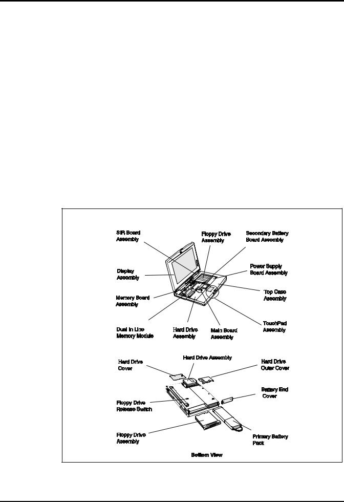
The Extensa Series Notebooks are modular in design and can be disassembled for maintenance purposes using a standard set of flat-bladed, Phillips-head and hexagonal screwdrivers. The major assemblies that comprise a typical notebook in the Extensa family are shown in Figure 1-7 and briefly described in the following paragraphs.
Figure 1-7 Notebook Assemblies
1-10 General Description

1.6.1Cover-Display Assembly
The Cover-Display Assembly contains the LCD screen and associated high voltage power supply and video circuitry. The Cover-Display Assembly contains three field-replaceable components including:
∙
∙
∙
LCD Assembly
Inverter Board
Slide Pot/Converter Board
The Cover-Display Assembly attaches to the System Base Assembly through four top mounted screws and six mounting screws on the bottom of the computer.
1.6.2System Base Assembly
As shown in Figure 1-7, the majority of the notebook’s field replaceable units (FRUs) are located in the system base assembly. These FRUs include:
∙
∙
∙
∙
∙
∙
∙
∙
∙
∙
∙
∙
∙
Main Board Assembly
Hard Disk Drive Assembly
Memory Board Assembly
Up to two Dual Inline Memory Modules
Serial Infra-red Board Assembly
Floppy Drive Assembly
Secondary Battery Board Assembly
Power Supply Board Assembly
Battery Pack Assembly
Top Case Assembly
Touchpad Assembly
Keyboard Assembly (removed in Figure 1-7 for clarity)
Battery Board Assembly
General Description 1-11

1.7 Extensa 450 Series Notebook
Specifications
Specifications for the Extensa 450 Series Notebooks are provided in Table 1-6.
Table 1-6 Extensa 450 Notebook Features
Specifications |
Models 450/450T |
Models 455/455T |
|
|
|
|
|
Memory: |
|
|
|
Standard: |
4MB |
4MB |
|
Maximum |
32MB |
32MB |
|
|
|
|
|
Display |
|
|
|
LCD Type: |
10.4" Dual Scan Color |
9.4" Active Matrix |
|
|
|||
|
|
Color |
|
Simultaneous LCD/Ext. |
Yes |
Yes |
|
VGA |
|||
|
|
||
Video RAM Size: |
512 KB |
512 KB |
|
|
|||
Video Bus |
VLBUS with Graphics |
VLBUS with Graphics |
|
|
|||
|
Accelerator |
Accelerator |
|
|
|
|
|
Keyboard/Pointing |
|
|
|
Device, |
|
|
|
Ergonomic Keyboard |
Yes |
Yes |
|
Built-In Touchpad |
Yes |
Yes |
|
|
|
|
|
Storage |
|
|
|
Floppy Drive: |
3.5", 1.44MB |
3.5", 1.44MB |
|
Hard Drive: |
340 Million Byte |
340 Million Byte |
|
|
|
|
|
Interfaces |
|
|
|
Serial (RS232) Port |
Yes (Port Adapter) |
Yes (Port Adapter) |
|
Parallel Port |
Yes |
|
|
(EPP/ECP), Yes |
|
|
|
External VGA Port |
Yes (Port Adapter) |
Yes (Port Adapter) |
|
External PS2 Ports |
Yes (2nd PS/2 Port on |
Yes (2nd PS/2 Port on |
|
|
Adapter) |
Adapter) |
|
Serial Infrared Port |
Yes |
Yes |
|
|
|
|
|
PCMCIA Support |
Type I/II (III Optional) |
Type I/II (III Optional) |
|
|
|||
|
|
|
|
|
|
|
1-12 General Description
Specifications |
Models 450/450T |
Models 455/455T |
|
|
|
Software |
Windows 95 |
Windows 95,plus |
|
||
|
|
applications |
|
|
|
Physical Characteristics |
|
|
Weight: |
Approx. 5.0 Pounds |
Approx. 5.0 Pounds |
|
(2.27kg) * |
(2.27kg) |
|
|
|
Dimensions: |
11.7” (L) X 1.7” (H) X |
11.7” (L) X 1.7” (H) X |
|
8.2” (W) |
8.2” (W) |
|
|
|
* Wight specifications |
|
|
do not include Floppy |
|
|
Drive, AC Adapter or |
|
|
2nd Battery |
|
|
|
|
|
|
|
|
1.8Agency Approvals
All Extensa 450 Series products meet the following standards:
∙Underwriter’s Lab (UL) Standard 1950 (safety)
∙Canadian Standards Association (CSA) Standard 220 (safety)
∙FCC CFR 47, Part 15, Subpart J, FCC Level B (EMI)
∙Canadian Department of Communications (DOC) Certification
∙VDE 0871, Class B (EMI)
General Description 1-13

2
Installation
2.1Introduction
This section contains unpacking and preparation for use instructions for the
Extensa 450 Series Notebook Computers.
2.2Unpacking Instructions
n
n
c
The packaging diagram for the notebook computer is shown in Figure 2-1. Unpack the computer using the following instructions:
1.Carefully cut the tape that seals the top flap of the shipping carton.
2.Remove the computer and the accessories from the main shipping carton.
3.Remove all protective coverings from the computer.
4.Remove the holding tape and open up the accessory box; remove the contents.
Note: Save the shipping containers and packaging for later reuse.
2.3Installing Notebook Options
If you have no options to install at this time, skip to Paragraph 2.3. Otherwise, continue with Paragraph 2.2.1.
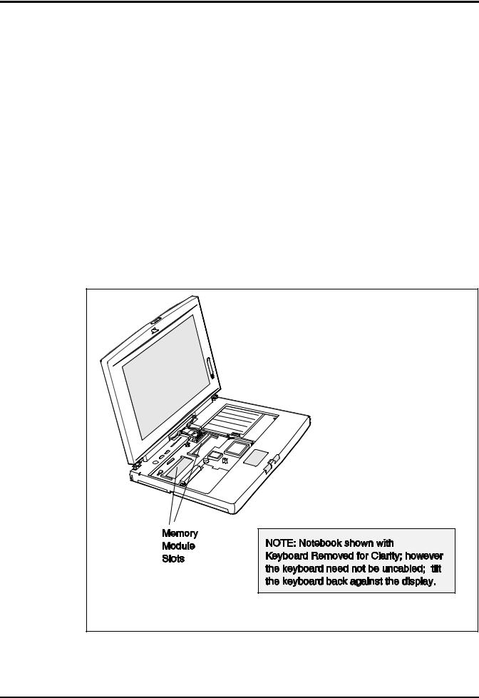
2.3.1Installing Dual Inline Memory Module(s)
Note: If not installing RAM Expansion option at this time, skip to the next paragraph.
Caution: The Dual Inline Memory Module contains components that are sensitive to static electricity. When handling the module and the internal parts of the computer, protect against static electricity by using wrist or ankle grounding straps and grounded working mats. When moving or storing items, use the anti-static bags supplied with the items.
Installation 2-1
1. |
Ensure that the notebook is powered off and that the AC Adapter and internal |
|
battery pack(s) is (are) removed from the notebook. |
2. |
Remove the DIMM module(s) from its shipping container. |
3. |
Release the Keyboard by pulling the keyboard release tabs forward (tabs are |
|
located underneath the Ctrl and right arrow keys). |
4Disengage the Keyboard using a straight blade screwdrive and gently lifting up along the front edge of the keyboard.
5Using the back edge of the keyboard as a hinge, lift the front edge of the keyboard up and lay it against the display.
6.Remove the two Phillips head screws holding heatsink to the Main Board and remove the heatsink by lifting it upwards and out of the unit.
7.Insert the edge of the DIMM Board into the rear of either available connector
(see Figure 2-1). Use a rocking motion to fully insert the module. Push downwards on each side of the DIMMs module until it snaps in place.
8. |
Replace the heatsink, keyboard assembly and any other components removed in |
|
step 1. |
This completes the expansion memory module installation procedure.
Figure 2-1 Installing Additional Memory
2-2 Installation
2.3.2Installing PCMCIA Options
The Notebook has provisions for one Type I or Type II PCMCIA option card.
However, a type III PCMCIA device can be installed if the Floppy Drive is removed from the notebook and the optional PCMCIA Module is installed..
1. |
Review the installation instructions supplied with the PCMCIA option card(s). |
2. |
Open the Type I/II PCMCIA compartment cover on the left side of the |
|
notebook. |
3. |
To insert a PCMCIA card, align the card with the socket and slide the card |
|
into the socket until it locks into place. To install a Type III option, you must |
|
remove the Floppy Drive from the right side of the notebookand install the |
|
PCMCIA Option Assembly.. |
4. |
To eject a PCMCIA card, first ensure that the notebook is not accessing the |
|
memory card or device. Under Windows 95, go to the Control Panel, PC Card |
|
and direct the card to stop before removing card. |
Type III PCMCIA
If Floppy Drive Removed and PCMCIA Option installed
Type 1 or Type II PCMCIA
Option
Figure 2-2 Installing PCMCIA Options
Installation 2-3
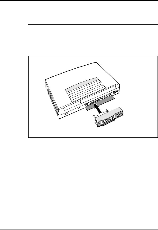
2.3.3Installing the Port Adapter
n Note: Skip this paragraph if not installing the Port Adapter at this time.
To install the Port Adapter, refer to Figure 2-3 and use the following procedure:
1Remove the -port adapter and any accessories from its shipping carton .
2Disconnect the AC Adapter from the notebook (if attached).
3Open the rear connector door on the notebook and attach the Port Adapter to the notebook as shown in Figure 2-3.
Figure 2-3 Installing the Port Adapter
2-4 Installation
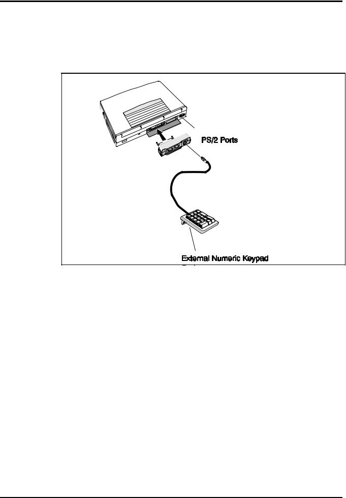
2.3.4Installing the Optional Numeric Keypad
An optional numeric keyboard can be attached to the notebook via the notebook’s
PS/2 connector as shown in Figure 2-4.
Figure 2-4 Installing the Numeric Keypad option
2.4Installing the Battery Pack(s )
The standard configuration of the Extensa Notebook is equipped with a single battery pack that is inserted from the front right side of the computer. However, if you can do without the Floppy Drive, you can use the floppy drive bay to house a second Lithium Ion battery pack.
To remove or replace the battery pack, follow the steps below.
1.Power off the notebook, being sure to save your data first.
2.Locate the battery door (right side of notebook near the front). Press the battery door inwards and slide the door toward the front of the notebook; remove the battery door.
3.Insert a new or recharged battery pack into the battery compartment bay. Make sure that the contacts are facing up and to the rear of the compartment.
Check the label (facing up when inserted) indicating the positive and negative poles of the battery.
Installation 2-5
c Caution: There is danger of explosion if the battery is incorrectly replaced. Replace the battery only with the same or an equivalent type recommended by the manufacturer. Discard used batteries according to the manufacturer’s instructions.
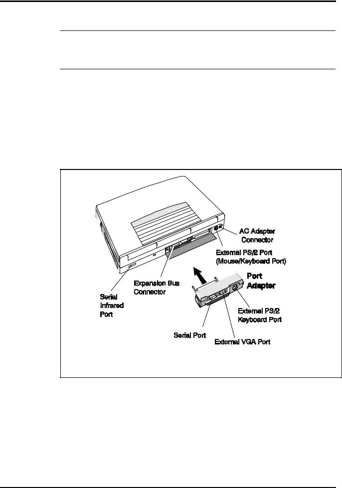
2.5Installing External Devices
Most external devices connect to the Notebook via the connectors on the rear of the notebook and on the rear of the Port Adapter supplied with the notebook (see Figure
2-5 for port assignments).
Figure 2-5 Extensa Port Assignments
2.5.1Installing an External Keyboard/Mouse
As shown in Figure 2-6, the notebook has provisions for two external PS/2 compatible devices (keyboard, mouse, etc.) that may be attached to the notebook. The pinouts for the 6-pin Mini-DIN connectors are also provided in Figure 2-6.
2-6 Installation
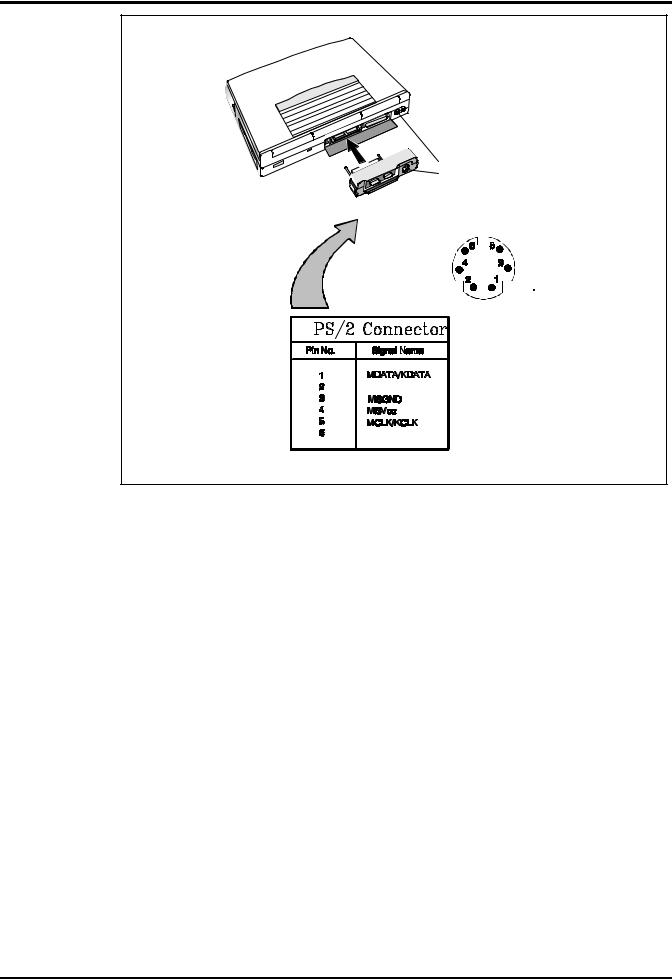
PS/2 Ports
Figure 2-6 PS/2 Port Assignments/Pinouts
To install an external keyboard or external PS/2 mouse on the notebook, use the following procedure:
1.Ensure that the notebook is powered off.
2.Locate the external PS/2 ports at the rear of the notebook (see Figure 2-6).
3.Attach the PS/2 cable from your mouse and/or keyboard cable to the PS/2 port(s).
4.Power on any other peripheral devices you may have connected to the notebook, and then power up the notebook.
Installation 2-7
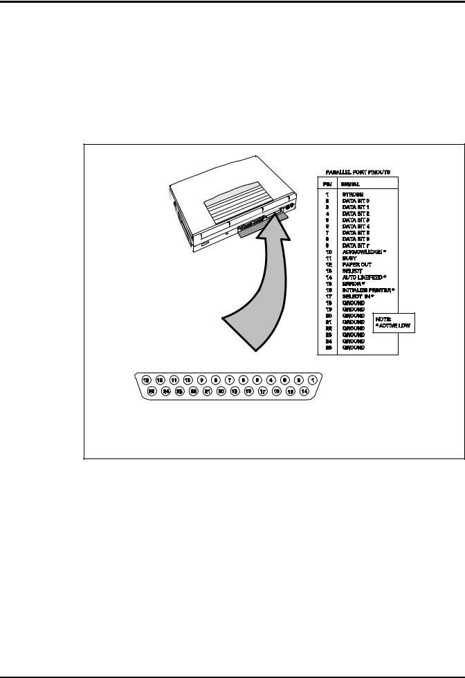
2.5.2Installing External Parallel Printer
The Notebook is equipped with a bi-directional, ECC/EPP compatible, 25-pin parallel printer port. The connector pinouts and connector location are shown in
Figure 2-7.
If you will be using a parallel interface, connect the 25-pin male connector of your printer cable to the 25-pin female parallel port on your notebook. Refer to the manual which accompanied your printer for instructions on configuring your operating environment
Figure 2-7 Parallel Port Location/Pinouts
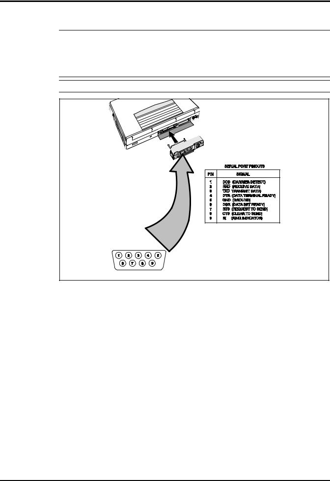
2.5.3Installing External Serial Port Device
The notebook contains an RS-232 serial port with a male DB-9 connector as shown in Figure 2-8. The serial ports are used to interconnect such devices as:
∙
∙
∙
External Modem
Serial Printer
Any device that uses an RS-232 interface
To connect a printer to the notebook, ensure that both the notebook and the printer are turned off.
2-8 Installation
c Caution: Never connect a parallel device to a serial port or a serial device to a parallel port or video port; this may cause damage to the Notebook and/or peripheral device. If you are uncertain of what type connector the external device has, refer to the technical manual for the external device.
Figure 2-8 Serial Port Location/Pinouts
Installation 2-9
 Loading...