


 Loading...
eMachines eM250 Series
Service Guide
Service guide files and updates are available on the ACER/CSD web; for more information, please refer to http://csd.acer.com.tw
PRINTED IN TAIWAN

Revision History
Please refer to the table below for the updates made to this service guide.
Date |
Chapter |
Updates |
|
|
|
|
|
|
|
|
|
|
|
|
II

Copyright
Copyright © 2009 by Acer Incorporated. All rights reserved. No part of this publication may be reproduced, transmitted, transcribed, stored in a retrieval system, or translated into any language or computer language, in any form or by any means, electronic, mechanical, magnetic, optical, chemical, manual or otherwise, without the prior written permission of Acer Incorporated.
Disclaimer
The information in this guide is subject to change without notice.
Acer Incorporated makes no representations or warranties, either expressed or implied, with respect to the contents hereof and specifically disclaims any warranties of merchantability or fitness for any particular purpose. Any Acer Incorporated software described in this manual is sold or licensed "as is". Should the programs prove defective following their purchase, the buyer (and not Acer Incorporated, its distributor, or its dealer) assumes the entire cost of all necessary servicing, repair, and any incidental or consequential damages resulting from any defect in the software.
Acer is a registered trademark of Acer Corporation. Intel is a registered trademark of Intel Corporation.
Other brand and product names are trademarks and/or registered trademarks of their respective holders.
III

Conventions
The following conventions are used in this manual:
SCREEN MESSAGES |
Denotes actual messages that appear |
|
on screen. |
|
|
NOTE |
Gives bits and pieces of additional |
|
information related to the current |
|
topic. |
|
|
WARNING |
Alerts you to any damage that might |
|
result from doing or not doing specific |
|
actions. |
|
|
CAUTION |
Gives precautionary measures to |
|
avoid possible hardware or software |
|
problems. |
|
|
IMPORTANT |
Reminds you to do specific actions |
|
relevant to the accomplishment of |
|
procedures. |
|
|
IV

Preface
Before using this information and the product it supports, please read the following general information.
1.This Service Guide provides you with all technical information relating to the BASIC CONFIGURATION decided for Acer's "global" product offering. To better fit local market requirements and enhance product competitiveness, your regional office MAY have decided to extend the functionality of a machine (e.g. add-on card, modem, or extra memory capability). These LOCALIZED FEATURES will NOT be covered in this generic service guide. In such cases, please contact your regional offices or the responsible personnel/channel to provide you with further technical details.
2.Please note WHEN ORDERING FRU PARTS, that you should check the most up-to-date information available on your regional web or channel. If, for whatever reason, a part number change is made, it will not be noted in the printed Service Guide. For ACER-AUTHORIZED SERVICE PROVIDERS, your Acer office may have a DIFFERENT part number code to those given in the FRU list of this printed Service Guide. You MUST use the list provided by your regional Acer office to order FRU parts for repair and service of customer machines.
V

VI

Table of Contents
System Specifications |
1 |
Features . . . . . . . . . . . . . . . . . . . . . . . . . . . . . . . . . . . . . . . . . . . . . . . . . . . . . . . . . . . .1 System Block Diagram . . . . . . . . . . . . . . . . . . . . . . . . . . . . . . . . . . . . . . . . . . . . . . . . .3 Your eMachines Notebook tour . . . . . . . . . . . . . . . . . . . . . . . . . . . . . . . . . . . . . . . . . .4 Front View . . . . . . . . . . . . . . . . . . . . . . . . . . . . . . . . . . . . . . . . . . . . . . . . . . . . . . .4 Closed Front View . . . . . . . . . . . . . . . . . . . . . . . . . . . . . . . . . . . . . . . . . . . . . . . . .5 Left View . . . . . . . . . . . . . . . . . . . . . . . . . . . . . . . . . . . . . . . . . . . . . . . . . . . . . . . .5 Right View . . . . . . . . . . . . . . . . . . . . . . . . . . . . . . . . . . . . . . . . . . . . . . . . . . . . . . .6 Rear and Base View . . . . . . . . . . . . . . . . . . . . . . . . . . . . . . . . . . . . . . . . . . . . . . .6 Indicators . . . . . . . . . . . . . . . . . . . . . . . . . . . . . . . . . . . . . . . . . . . . . . . . . . . . . . .7 TouchPad Basics . . . . . . . . . . . . . . . . . . . . . . . . . . . . . . . . . . . . . . . . . . . . . . . . .8 Using the Keyboard . . . . . . . . . . . . . . . . . . . . . . . . . . . . . . . . . . . . . . . . . . . . . . . . . . .9 Lock Keys and embedded numeric keypad . . . . . . . . . . . . . . . . . . . . . . . . . . . . .9 Windows Keys . . . . . . . . . . . . . . . . . . . . . . . . . . . . . . . . . . . . . . . . . . . . . . . . . .10 Hot Keys . . . . . . . . . . . . . . . . . . . . . . . . . . . . . . . . . . . . . . . . . . . . . . . . . . . . . . .11 Special Keys . . . . . . . . . . . . . . . . . . . . . . . . . . . . . . . . . . . . . . . . . . . . . . . . . . . .12
Hardware Specifications and Configurations . . . . . . . . . . . . . . . . . . . . . . . . . . . . . . .13
System Utilities |
19 |
BIOS Setup Utility . . . . . . . . . . . . . . . . . . . . . . . . . . . . . . . . . . . . . . . . . . . . . . . . . . . .19
Navigating the BIOS Utility . . . . . . . . . . . . . . . . . . . . . . . . . . . . . . . . . . . . . . . . .19
Information . . . . . . . . . . . . . . . . . . . . . . . . . . . . . . . . . . . . . . . . . . . . . . . . . . . . .20
Main . . . . . . . . . . . . . . . . . . . . . . . . . . . . . . . . . . . . . . . . . . . . . . . . . . . . . . . . . .21
Security . . . . . . . . . . . . . . . . . . . . . . . . . . . . . . . . . . . . . . . . . . . . . . . . . . . . . . . .22
Boot . . . . . . . . . . . . . . . . . . . . . . . . . . . . . . . . . . . . . . . . . . . . . . . . . . . . . . . . . . .25
Exit . . . . . . . . . . . . . . . . . . . . . . . . . . . . . . . . . . . . . . . . . . . . . . . . . . . . . . . . . . .26
BIOS Flash Utility . . . . . . . . . . . . . . . . . . . . . . . . . . . . . . . . . . . . . . . . . . . . . . . . . . . .27
DOS Flash Utility . . . . . . . . . . . . . . . . . . . . . . . . . . . . . . . . . . . . . . . . . . . . . . . . .28
WinFlash Utility . . . . . . . . . . . . . . . . . . . . . . . . . . . . . . . . . . . . . . . . . . . . . . . . . .30
Remove HDD/BIOS Password Utilities . . . . . . . . . . . . . . . . . . . . . . . . . . . . . . . . . . . .31
Miscellaneous Utilities . . . . . . . . . . . . . . . . . . . . . . . . . . . . . . . . . . . . . . . . . . . . .33
Machine Disassembly and Replacement |
37 |
Disassembly Requirements . . . . . . . . . . . . . . . . . . . . . . . . . . . . . . . . . . . . . . . . . . . |
.37 |
Related Information . . . . . . . . . . . . . . . . . . . . . . . . . . . . . . . . . . . . . . . . . . . . . . |
.37 |
General Information . . . . . . . . . . . . . . . . . . . . . . . . . . . . . . . . . . . . . . . . . . . . . . . . . |
.38 |
Pre-disassembly Instructions . . . . . . . . . . . . . . . . . . . . . . . . . . . . . . . . . . . . . . |
.38 |
Disassembly Process . . . . . . . . . . . . . . . . . . . . . . . . . . . . . . . . . . . . . . . . . . . . . |
38 |
External Module Disassembly Process . . . . . . . . . . . . . . . . . . . . . . . . . . . . . . . . . . . |
39 |
External Modules Disassembly Flowchart . . . . . . . . . . . . . . . . . . . . . . . . . . . . . |
39 |
Removing the Battery Pack . . . . . . . . . . . . . . . . . . . . . . . . . . . . . . . . . . . . . . . . |
40 |
Removing the Lower Covers . . . . . . . . . . . . . . . . . . . . . . . . . . . . . . . . . . . . . . . . |
41 |
Removing the Hard Disk Drive Module . . . . . . . . . . . . . . . . . . . . . . . . . . . . . . . . |
43 |
Removing the DIMM Module . . . . . . . . . . . . . . . . . . . . . . . . . . . . . . . . . . . . . . . |
45 |
Removing the 3G Module . . . . . . . . . . . . . . . . . . . . . . . . . . . . . . . . . . . . . . . . . . |
46 |
Main Unit Disassembly Process . . . . . . . . . . . . . . . . . . . . . . . . . . . . . . . . . . . . . . . . . |
48 |
Main Unit Disassembly Flowchart . . . . . . . . . . . . . . . . . . . . . . . . . . . . . . . . . . . . |
48 |
Removing the Keyboard . . . . . . . . . . . . . . . . . . . . . . . . . . . . . . . . . . . . . . . . . . . |
49 |
Removing the Upper Cover . . . . . . . . . . . . . . . . . . . . . . . . . . . . . . . . . . . . . . . . |
51 |
Removing the Power Board . . . . . . . . . . . . . . . . . . . . . . . . . . . . . . . . . . . . . . . . |
55 |
Removing the Bluetooth Module . . . . . . . . . . . . . . . . . . . . . . . . . . . . . . . . . . . . . |
57 |
Removing the TouchPad FFC . . . . . . . . . . . . . . . . . . . . . . . . . . . . . . . . . . . . . . |
58 |
Removing the WLAN Board . . . . . . . . . . . . . . . . . . . . . . . . . . . . . . . . . . . . . . . . |
59 |
Removing the USB Board . . . . . . . . . . . . . . . . . . . . . . . . . . . . . . . . . . . . . . . . . . |
61 |
VII

Table of Contents
Removing the Mainboard . . . . . . . . . . . . . . . . . . . . . . . . . . . . . . . . . . . . . . . . . .63
Removing the RTC Battery . . . . . . . . . . . . . . . . . . . . . . . . . . . . . . . . . . . . . . . . .66
Removing the Thermal Module . . . . . . . . . . . . . . . . . . . . . . . . . . . . . . . . . . . . . .67
Removing the Speaker Module . . . . . . . . . . . . . . . . . . . . . . . . . . . . . . . . . . . . . .69
Removing the LCD Module . . . . . . . . . . . . . . . . . . . . . . . . . . . . . . . . . . . . . . . . .71
Removing the AC Power Jack . . . . . . . . . . . . . . . . . . . . . . . . . . . . . . . . . . . . . .74
LCD Module Disassembly Process . . . . . . . . . . . . . . . . . . . . . . . . . . . . . . . . . . . . . .75
LCD Module Disassembly Flowchart . . . . . . . . . . . . . . . . . . . . . . . . . . . . . . . . .75
Removing the LCD Bezel . . . . . . . . . . . . . . . . . . . . . . . . . . . . . . . . . . . . . . . . . .76
Removing the Camera Board . . . . . . . . . . . . . . . . . . . . . . . . . . . . . . . . . . . . . . .78
Removing the LCD Panel . . . . . . . . . . . . . . . . . . . . . . . . . . . . . . . . . . . . . . . . . .79
Removing the LCD Brackets and FPC Cable . . . . . . . . . . . . . . . . . . . . . . . . . . .81
Removing the Antennas . . . . . . . . . . . . . . . . . . . . . . . . . . . . . . . . . . . . . . . . . . .83
LCD Module Reassembly Procedure . . . . . . . . . . . . . . . . . . . . . . . . . . . . . . . . . . . . .86
Replacing the Antennas . . . . . . . . . . . . . . . . . . . . . . . . . . . . . . . . . . . . . . . . . . .86
Replacing the LCD Cable and Brackets . . . . . . . . . . . . . . . . . . . . . . . . . . . . . . .89
Replacing the LCD Panel . . . . . . . . . . . . . . . . . . . . . . . . . . . . . . . . . . . . . . . . . .92
Replacing the Camera Board . . . . . . . . . . . . . . . . . . . . . . . . . . . . . . . . . . . . . . .93
Replacing the LCD Bezel . . . . . . . . . . . . . . . . . . . . . . . . . . . . . . . . . . . . . . . . . .95
Main Module Reassembly Procedure . . . . . . . . . . . . . . . . . . . . . . . . . . . . . . . . . . . . .96
Replacing the AC Power Jack . . . . . . . . . . . . . . . . . . . . . . . . . . . . . . . . . . . . . .96
Replacing the LCD Module . . . . . . . . . . . . . . . . . . . . . . . . . . . . . . . . . . . . . . . . .97
Replacing the Speaker Module . . . . . . . . . . . . . . . . . . . . . . . . . . . . . . . . . . . . .100
Replacing the Thermal Module . . . . . . . . . . . . . . . . . . . . . . . . . . . . . . . . . . . . .101
Replacing the Mainboard . . . . . . . . . . . . . . . . . . . . . . . . . . . . . . . . . . . . . . . . .102
Replacing the USB Board . . . . . . . . . . . . . . . . . . . . . . . . . . . . . . . . . . . . . . . . .104
Replacing the WLAN Board . . . . . . . . . . . . . . . . . . . . . . . . . . . . . . . . . . . . . . .105
Replacing the TouchPad FFC . . . . . . . . . . . . . . . . . . . . . . . . . . . . . . . . . . . . . .106
Replacing the Bluetooth Module . . . . . . . . . . . . . . . . . . . . . . . . . . . . . . . . . . . .106
Replacing the Power Board . . . . . . . . . . . . . . . . . . . . . . . . . . . . . . . . . . . . . . .108
Replacing the Upper Cover . . . . . . . . . . . . . . . . . . . . . . . . . . . . . . . . . . . . . . . .110
Replacing the Keyboard . . . . . . . . . . . . . . . . . . . . . . . . . . . . . . . . . . . . . . . . . .113
Replacing the 3G Module . . . . . . . . . . . . . . . . . . . . . . . . . . . . . . . . . . . . . . . . .113
Replacing the DIMM Module . . . . . . . . . . . . . . . . . . . . . . . . . . . . . . . . . . . . . . .115
Replacing the Hard Disk Drive Module . . . . . . . . . . . . . . . . . . . . . . . . . . . . . . .115
Replacing the Lower Covers . . . . . . . . . . . . . . . . . . . . . . . . . . . . . . . . . . . . . . .117
Replacing the Battery Pack . . . . . . . . . . . . . . . . . . . . . . . . . . . . . . . . . . . . . . . .118
Troubleshooting |
119 |
Common Problems . . . . . . . . . . . . . . . . . . . . . . . . . . . . . . . . . . . . . . . . . . . . . . . . . .119
Power On Issue . . . . . . . . . . . . . . . . . . . . . . . . . . . . . . . . . . . . . . . . . . . . . . . .120
No Display Issue . . . . . . . . . . . . . . . . . . . . . . . . . . . . . . . . . . . . . . . . . . . . . . . .121
Random Loss of BIOS Settings . . . . . . . . . . . . . . . . . . . . . . . . . . . . . . . . . . . .122
LCD Failure . . . . . . . . . . . . . . . . . . . . . . . . . . . . . . . . . . . . . . . . . . . . . . . . . . . .123
Built-In Keyboard Failure . . . . . . . . . . . . . . . . . . . . . . . . . . . . . . . . . . . . . . . . .123
TouchPad Failure . . . . . . . . . . . . . . . . . . . . . . . . . . . . . . . . . . . . . . . . . . . . . . .124
Internal Speaker Failure . . . . . . . . . . . . . . . . . . . . . . . . . . . . . . . . . . . . . . . . . .125
Internal Microphone Failure . . . . . . . . . . . . . . . . . . . . . . . . . . . . . . . . . . . . . . .127
HDD Not Operating Correctly . . . . . . . . . . . . . . . . . . . . . . . . . . . . . . . . . . . . . .128
USB Failure (Rightside) . . . . . . . . . . . . . . . . . . . . . . . . . . . . . . . . . . . . . . . . . .129
Wireless Function Test Failure . . . . . . . . . . . . . . . . . . . . . . . . . . . . . . . . . . . . .130
3G Function Test Failure . . . . . . . . . . . . . . . . . . . . . . . . . . . . . . . . . . . . . . . . .131
Switch Failure . . . . . . . . . . . . . . . . . . . . . . . . . . . . . . . . . . . . . . . . . . . . . . . . . .132
Thermal Units Failure . . . . . . . . . . . . . . . . . . . . . . . . . . . . . . . . . . . . . . . . . . . .133
Power Button Failure . . . . . . . . . . . . . . . . . . . . . . . . . . . . . . . . . . . . . . . . . . . .133
VIII

Table of Contents
External Mouse Failure . . . . . . . . . . . . . . . . . . . . . . . . . . . . . . . . . . . . . . . . . . .134 Other Failures . . . . . . . . . . . . . . . . . . . . . . . . . . . . . . . . . . . . . . . . . . . . . . . . . .134 Intermittent Problems . . . . . . . . . . . . . . . . . . . . . . . . . . . . . . . . . . . . . . . . . . . . . . . .135 Undetermined Problems . . . . . . . . . . . . . . . . . . . . . . . . . . . . . . . . . . . . . . . . . . . . . .135 Motherboard CMOS Discharge . . . . . . . . . . . . . . . . . . . . . . . . . . . . . . . . . . . . . . . .136 POST Code Reference Tables . . . . . . . . . . . . . . . . . . . . . . . . . . . . . . . . . . . . . . . . .137 Sec: . . . . . . . . . . . . . . . . . . . . . . . . . . . . . . . . . . . . . . . . . . . . . . . . . . . . . . . . . .137 Memory: . . . . . . . . . . . . . . . . . . . . . . . . . . . . . . . . . . . . . . . . . . . . . . . . . . . . . .137 BDS & Specific action: . . . . . . . . . . . . . . . . . . . . . . . . . . . . . . . . . . . . . . . . . . .138 Each PEIM entry point used in 80_PORT . . . . . . . . . . . . . . . . . . . . . . . . . . . . .139 Each Driver entry point used in 80_PORT . . . . . . . . . . . . . . . . . . . . . . . . . . . .139 Each SmmDriver entry point used in 80_PORT . . . . . . . . . . . . . . . . . . . . . . . .142
Jumper and Connector Locations |
143 |
Top View . . . . . . . . . . . . . . . . . . . . . . . . . . . . . . . . . . . . . . . . . . . . . . . . . . . . . . . . . |
.143 |
Bottom View . . . . . . . . . . . . . . . . . . . . . . . . . . . . . . . . . . . . . . . . . . . . . . . . . . . . . . |
.144 |
Power board . . . . . . . . . . . . . . . . . . . . . . . . . . . . . . . . . . . . . . . . . . . . . . . . . . . . . . |
.145 |
Card reader board . . . . . . . . . . . . . . . . . . . . . . . . . . . . . . . . . . . . . . . . . . . . . . . . . |
.146 |
Clearing Password Check and BIOS Recovery . . . . . . . . . . . . . . . . . . . . . . . . . . . |
.147 |
Clearing Password Check . . . . . . . . . . . . . . . . . . . . . . . . . . . . . . . . . . . . . . . . |
.147 |
BIOS Recovery by Crisis Disk . . . . . . . . . . . . . . . . . . . . . . . . . . . . . . . . . . . . |
.148 |
FRU (Field Replaceable Unit) List |
149 |
eMachines eM250 Exploded Diagrams . . . . . . . . . . . . . . . . . . . . . . . . . . . . . . . . . .150
Main Assembly . . . . . . . . . . . . . . . . . . . . . . . . . . . . . . . . . . . . . . . . . . . . . . . . .150
Rear Assembly . . . . . . . . . . . . . . . . . . . . . . . . . . . . . . . . . . . . . . . . . . . . . . . . .151
Upper Cover Assembly . . . . . . . . . . . . . . . . . . . . . . . . . . . . . . . . . . . . . . . . . . .152
Lower Cover Assembly . . . . . . . . . . . . . . . . . . . . . . . . . . . . . . . . . . . . . . . . . . .153
LCD Assembly . . . . . . . . . . . . . . . . . . . . . . . . . . . . . . . . . . . . . . . . . . . . . . . . .154
eMachines eM250 FRU List . . . . . . . . . . . . . . . . . . . . . . . . . . . . . . . . . . . . . . .155
Screw List . . . . . . . . . . . . . . . . . . . . . . . . . . . . . . . . . . . . . . . . . . . . . . . . . . . . .162
Model Definition and Configuration |
164 |
eMachines eM250 Series . . . . . . . . . . . . . . . . . . . . . . . . . . . . . . . . . . . . . . . . . . . . .164
Model eM250-01G16i . . . . . . . . . . . . . . . . . . . . . . . . . . . . . . . . . . . . . . . . . . . .165
Model eM250-01G25i . . . . . . . . . . . . . . . . . . . . . . . . . . . . . . . . . . . . . . . . . . . .170
Model eM250-02G16i . . . . . . . . . . . . . . . . . . . . . . . . . . . . . . . . . . . . . . . . . . . .171
Model eM250-02G25i . . . . . . . . . . . . . . . . . . . . . . . . . . . . . . . . . . . . . . . . . . . .171
Test Compatible Components |
173 |
Windows XP Environment Test . . . . . . . . . . . . . . . . . . . . . . . . . . . . . . . . . . . . . . . |
.174 |
Online Support Information |
181 |
Index |
183 |
IX

Table of Contents
X
Chapter 1
System Specifications
Features
Below is a brief summary of the computer’s many features:
Operating System
•Genuine Windows® 7 Starter
•Genuine Windows® 7 Home Basic (China only)
•Genuine Windows® XP Home (Service Pack 3)
Platform
•Intel® Atom™ processor
•Mobile Intel® 945GSE Express Chipset
•Mobile Intel® 82801GBM Chipset
•Acer InviLink™ 802.11b/g
System Memory
•Single channel with one soDIMM slot:
•DDR2 533/667 MHz SDRAM memory interface design
•soDIMM slot: Supports 512 MB / 1 GB / 2 GB soDIMMs for total system memory of up to 2 GB
Display and graphics
•10.1" WSVGA high-brightness (typical 180-nit) Acer CrystalBrite™ TFT LCD, 1024 x 600 pixel resolution
•Mobile Intel® 945GSE Express Chipset
Storage subsystem
•2.5" 9.5 mm 160 GB or larger hard disk drive
•Multi-in-1 card reader
Audio
•High-definition audio support
•Two built-in stereo speakers
•MS-Sound compatible
•Built-in digital microphone
Dimensions and Weight
•258.5 (W) x 184 (D) x 25.4 (H) mm
Chapter 1 |
1 |

•1.18 kg (2.62 lbs.) for SKUs with 3-cell battery pack
•1.33 kg (2.95 lbs.) for SKUs with 6-cell battery pack
Communication
•Integrated webcam, supporting 0.3-megapixel resolution
•WLAN: Acer InviLink™ 802.11b/g Wi-Fi CERTIFIED® network connection, supporting Acer SignalUp™ wireless technology
•LAN: 10/100 Mbps Fast Ethernet
•WPAN: Bluetooth® 2.0+EDR
•WWAN: UMTS/HSPA at 2100 MHz and quad-band GSM/GPRS/EDGE (850/900/1800/1900 MHz), or UMTS/HSPA at 850/1900/2100 MHz and quad-band GSM/GPRS/EDGE (850/900/1800/1900 MHz) (for 3G models)
Privacy control
•BIOS user, supervisor, HDD passwords
•Kensington lock slot
Special keys and controls
•84-key keyboard with 1.6 mm (minimum) key travel
•Touchpad pointing device with two buttons
Power
•24.4 W 2200 mAh 3-cell Li-ion battery pack, 3-hour battery life
•48.8 W 4400 mAh 6-cell Li-ion battery pack, 6-hour battery life
•57.7 W 5200 mAh 6-cell Li-ion battery pack, 7-hour battery life
•30 W adapter with power cord
I/O interface
•Multi-in-1 card reader
•Three USB 2.0 ports
•External display (VGA) port
•Headphone/speaker/line-out jack
•Microphone-in jack
•Ethernet (RJ-45) port
•DC-in jack for AC adapter
Environment
•Temperature:
•Operating: 5 °C to 35 °C
•Non-operating: -20 °C to 65 °C
•Humidity (non-condensing):
•Operating: 20% to 80%
•Non-operating: 20% to 80%
2 |
Chapter 1 |
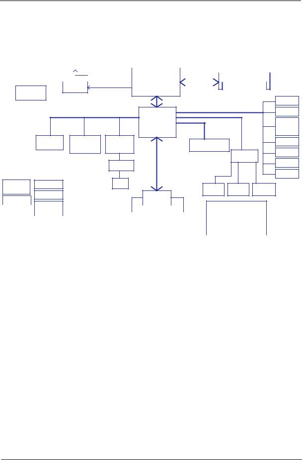
System Block Diagram
|
|
|
|
Diamondville SC |
|
|
|
|
|
|
|
||
|
|
|
|
|
FCBGA8 |
|
|
|
|
|
|
|
|
|
|
|
|
|
437Pins |
|
|
|
|
|
|
|
|
|
|
|
|
|
22x22mm |
|
|
|
|
|
|
|
|
|
|
|
|
|
page 4,5 |
|
|
|
|
|
|
||
CRT Conn |
|
|
|
FSB |
|
|
|
|
|
Clock Generator |
|
||
H_A#(3..31) |
|
|
H_D#(0..63) |
|
|
CK505 page 12 |
|
|
|||||
|
400/533MHz |
|
|
|
|
||||||||
|
page 14 |
RGB |
|
|
|
|
|
|
|
|
|
|
|
|
|
|
|
|
|
|
|
|
|
|
|
|
|
|
|
|
|
|
|
|
|
|
|
|
|
|
|
|
|
Calistoga GSE |
|
Memory BUS(DDRII) |
DDRII-SO-DIMM |
||||||||
|
|
|
|
|
|||||||||
|
|
|
|
FCBGA998 |
|
|
|
|
|
page 11 |
|||
|
|
|
|
|
|
|
|
|
|
|
|||
|
|
LCD Conn. |
LVDS |
|
1.8V DDRII 400/533 |
|
|
|
Thermal Sensor |
27x27mm |
|
|
|
|
|||
page 13 |
|
|
|
|
|
|||
EMC1402 |
|
|
|
page 6,7,8,9,10 |
|
|
|
|
page 4 |
|
|
|
|
|
|
|
|
|
|
DMI |
|
|
|
|
USB Port X1 |
|
|
|
|
|
|
|
|
||
|
|
|
X2 mode |
|
|
|
page 28 |
|
|
|
|
|
|
|
|
||
|
|
|
|
ICH7M |
|
|
USB |
I/O Board X2 |
|
|
|
PCI-Express |
|
|
HDA |
||
|
|
|
|
|
page 22 |
|||
|
|
|
|
BGA652 |
|
|
|
to I/O board |
|
|
|
|
|
|
|
|
|
|
|
|
|
31x31mm |
|
|
|
CONN |
|
|
|
|
|
|
|
RTS5159E |
|
|
|
|
|
|
|
|
|
|
|
|
|
|
page 15,16,17,18 |
|
SATA |
|
page 22 |
|
|
|
|
|
|
|
||
|
|
|
10/100 Ethernet |
|
|
|
|
|
|
SDIO CONN |
MINI Card x2 |
|
to I/OBoard CONN |
|
BlueToothX1 |
||
|
|
|
|
|||||
|
|
|
AR8114A |
|
|
page19 |
||
|
|
|
|
|
|
|
|
|
|
page 27 |
|
|
|
JP7 |
page 22 |
|
|
|
|
page 19 |
page 24 |
|
|
|
CMOS CAM |
|
|
|
|
|
|
Aralia Codec |
|||
|
|
|
|
|
|
|
||
|
|
|
|
LPC BUS |
|
|
page13 |
|
|
|
|
|
|
|
ALC272 |
|
|
|
|
|
|
|
|
|
page 20 |
WLANX1 |
|
|
|
Transfermer |
|
|
|
|
|
|
|
|
|
|
|
|
page19 |
|
|
|
|
page 24 |
|
|
|
|
|
|
|
|
|
|
|
|
|
WWANX1 |
|
|
|
|
|
|
|
|
page19 |
Power ON/OFF |
DC/DC Interface |
|
RJ45 |
|
|
|
|
|
|
|
|
|
|
|
|
||
& LED CONN |
page 29 |
|
page 24 |
|
|
AMP & INT |
HeadPhone & |
INT DMIC CONN |
|
|
|
|
|
MIC Jack |
|
||
page 26 |
|
|
|
|
|
Speaker |
|
|
|
|
|
|
|
page 21 |
page 13 |
||
|
3VALW/5VALW |
|
|
ENE KBC |
SPI |
page 21 |
||
|
|
|
|
|
|
|||
DC IN |
page 33 |
|
|
KB926 |
|
|
|
|
|
|
|
|
|
|
|
||
page 31 |
|
|
|
page 25 |
|
|
|
|
|
|
1.5VS/0.9VS/ |
|
|
|
|
|
|
|
|
I/O board |
|
|
|
|
BATT IN |
|
2.5VS |
|
|
|
|
|
|
|
|
|
SATA CONN |
|
|
|
page 32 |
|
page 36 |
Int.KBD |
|
|
|
|
|
SPI ROM |
|
|
|
|
|
|
|
|
|
|
page 27 |
|
|
|
|
|
page 25 |
|
|
USB Port X2 |
|
|
CHARGER |
|
1.8V/VCCP |
|
|
|
Touch Pad |
|
|
|
|
|||||
|
|
|
|
|
|
|
|
|
|
||||||
|
|
|
|
|
|
|
|
|
|
|
|
||||
page 34 |
|
page 35 |
|
|
|
|
|
page 27 |
|
|
|
|
USB Card Reader |
|
|
|
|
|
|
|
|
|
|
|
|
|
|
||||
|
|
|
|
|
|
|
|
|
|
|
|
|
x1 RTS5159E |
|
|
|
|
CPU_CORE |
|
|
|
|
|
|
|
|
|
|
|
||
|
|
|
|
|
|
|
|
|
|
|
|
|
|
|
|
|
|
page 37 |
|
|
|
|
|
|
|
|
|
|
|
|
|
Chapter 1 |
3 |
Your eMachines Notebook tour
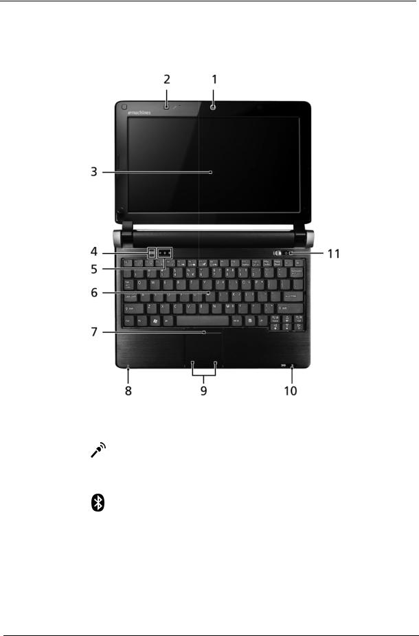
Front View
No. |
Icon |
Item |
Description |
|
|
|
|
1 |
|
Webcam |
Web camera for video communication |
|
|
|
|
2 |
|
Microphone |
Internal microphone for sound |
|
|
|
recording. |
|
|
|
|
3 |
|
Display screen |
Also called Liquid-Crystal Display (LCD), |
|
|
|
displays computer output. |
|
|
|
|
4 |
|
Bluetooth |
Enables/disables the Bluetooth function. |
|
|
communication |
Indicates the status of Bluetooth communication. |
|
|
switch/indicator |
(only for certain models) |
|
|
|
|
5 |
|
Status indicators |
Light-Emitting Diodes (LED) that light up to show |
|
|
|
the status of the computer's functions and |
|
|
|
components. |
|
|
|
|
6 |
|
Keyboard |
For entering data into your computer. |
|
|
|
|
7 |
|
TouchPad |
Touch-sensitive pointing device which functions like |
|
|
|
a computer mouse. |
8 |
|
Power indicator |
Indicates the computer's power status. |
|
|
|
|
4 |
Chapter 1 |
No. |
Icon |
Item |
Description |
|
|
|
|
9 |
|
Click buttons (left |
The left and right buttons function like the left and |
|
|
and right) |
right mouse buttons. |
|
|
|
|
10 |
|
Wireless LAN/3G |
Indicates the status of Wireless LAN/3G |
|
|
communication |
communication. (only for certain models) |
|
|
indicator |
|
|
|
|
|
11 |
|
Power button/ |
Turns the computer on and off. |
|
|
indicator |
|
|
|
|
|
Closed Front View
No. |
Icon |
Item |
Description |
|
|
|
|
1 |
|
Wireless |
Enables/disables the wireless function. |
|
|
communication |
|
|
|
switch |
|
|
|
|
|
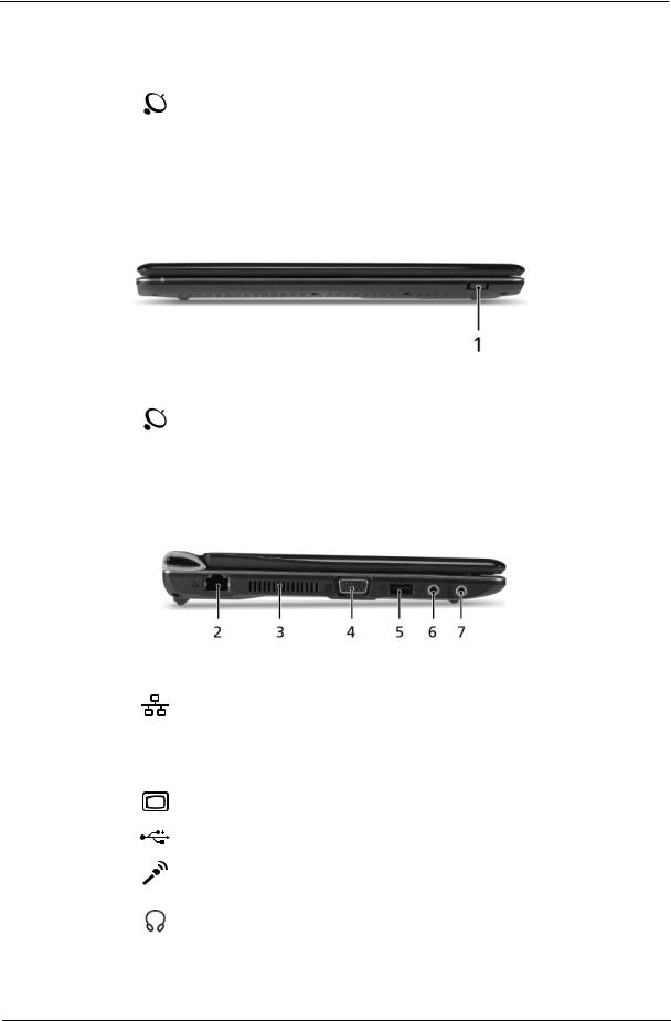
Left View
|
|
|
|
|
|
|
|
|
|
|
1 |
2 |
3 |
4 |
5 |
6 |
|
||
|
|
|
|
|
|
|
|
|
|
No. |
Icon |
|
|
Item |
|
|
|
Description |
|
|
|
|
|
|
|
||||
1 |
|
|
Ethernet (RJ-45) |
Connects to an Ethernet 10/100-based |
|||||
|
|
|
port |
|
network. |
|
|
|
|
|
|
|
|
|
|
||||
2 |
|
|
Ventilation slots |
Enable the computer to stay cool, even after |
|||||
|
|
|
and cooling fan |
prolonged use. |
|
|
|
||
|
|
|
|
|
Note: Do not cover or obstruct the fan opening. |
||||
|
|
|
|
|
|
||||
3 |
|
|
External display |
Connects to a display device |
|||||
|
|
|
(VGA) port |
(e.g. external monitor, projector). |
|||||
|
|
|
|
|
|
||||
4 |
|
|
USB 2.0 port |
Connect to USB 2.0 devices (e.g. USB mouse). |
|||||
|
|
|
|
|
|
||||
6 |
|
|
Microphone-in |
Accepts input from external microphones. |
|||||
|
|
|
jack |
|
|
|
|
|
|
|
|
|
|
|
|
||||
5 |
|
|
Headphones/ |
Connects to line-out audio devices |
|||||
|
|
|
speaker/line-out |
(e.g. speakers, headphones). |
|||||
|
|
|
jack |
|
|
|
|
|
|
|
|
|
|
|
|
|
|
|
|
Chapter 1 |
5 |
Right View
|
|
|
|
|
|
|
1 |
2 |
3 |
4 |
|
|
|
|
|
|
|
|
|
|
|
|
|
No. |
|
Icon |
|
Item |
Description |
||||||
|
|
|
|
|
|
|
|
|
|
||
1 |
|
|
|
|
|
|
|
Multi-in-1 card |
Accepts Secure Digital (SD), MultiMediaCard |
||
|
|
|
|
|
|
|
|
reader |
|
(MMC), Memory Stick (MS), Memory Stick PRO |
|
|
|
|
|
|
|
|
|
|
|
(MS PRO), xD-Picture Card (xD). |
|
|
|
|
|
|
|
|
|
|
|
Note: Push to remove/install the card. Only one |
|
|
|
|
|
|
|
|
|
|
|
card can operate at any given time. |
|
2 |
|
|
|
|
|
|
|
USB 2.0 ports |
Connect to USB 2.0 devices (e.g. USB mouse). |
||
|
|
|
|
|
|
|
|
|
|
||
3 |
|
|
|
|
|
|
|
DC-in jack |
Connects to an AC adapter |
||
|
|
|
|
|
|
|
|||||
|
|
|
|
|
|
|
|||||
|
|
|
|
|
|
|
|
|
|
|
|
4 |
|
|
|
|
|
|
|
Kensington lock |
Connects to a Kensington-compatible computer |
||
|
|
|
|
|
|
|
|
slot |
|
security lock. |
|
|
|
|
|
|
|
|
|
|
|
|
|
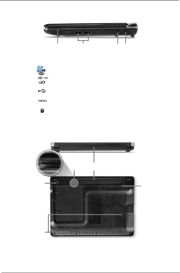
Rear and Base View
5 1
2
4
3
No. |
Icon |
Item |
Description |
|
|
|
|
1 |
|
Battery bay |
Houses the computer's battery pack. |
|
|
|
Note: The battery shown is for reference only. Your |
|
|
|
PC may have a different battery, depending on the |
|
|
|
model purchased. |
|
|
|
|
6 |
Chapter 1 |
No. |
Icon |
Item |
Description |
||
|
|
|
|
|
|
2 |
|
|
|
Battery lock |
Locks the battery in position. |
|
|
|
|
|
|
3 |
|
|
|
Ventilation slots |
Vents enable the computer to stay cool, even after |
|
|
|
|
|
prolonged use. |
|
|
|
|
|
Note: Do not cover or obstruct the cooling vents. |
|
|
|
|
|
|
4 |
|
|
|
Battery release |
Releases the battery for removal. |
|
|
|
|
latch |
|
|
|
|
|
|
|
5 |
|
|
|
3G SIM card slot |
Accepts a 3G SIM card for 3G connectivity (only for |
|
|
|
|
|
certain models). |
|
|
|
|
|
|
Indicators
The computer has several easy-to-read status indicators. The battery indicator is visible even when the computer cover is closed.
|
|
|
Icon |
Function |
Description |
|
|
|
|
|
|
|
|
|
|
Bluetooth |
Indicates the status of Bluetooth communication. |
|
|
|
|
|
|
|
|
|
|
Wireless LAN |
Indicates the status of Wireless LAN communication. |
|
|
|
|
|
|
|
|
|
|
3G communication |
Indicates the status of 3G communication. |
|
|
|
|
|
|
|
|
|
|
HDD |
Indicates when the hard disk drive is active. |
|
|
|
|
|
|
|
|
|
|
Num Lock |
Lights up when Num Lock is activated. |
|
|
|
|
|
|
|
|
|
|
|
|
|
|
|
|
Caps Lock |
Lights up when Caps Lock is activated. |
|
|
|
|
|
|
|
|
|
|
Battery |
Indicates the computer's battery status. |
|
|
|
|
||
|
|
|
|
|
|
|
|
|
|
|
|
Chapter 1 |
7 |

TouchPad Basics
The following items show you how to use the TouchPad:
•Move your finger across the TouchPad (1) to move the cursor.
•Press the left (2) and right (3) buttons located beneath the TouchPad to perform selection and execution functions. These two buttons are similar to the left and right buttons on a mouse. Tapping on the TouchPad is the same as clicking the left button.
Function |
Left Button (2) |
Right Button (3) |
Main TouchPad (1) |
|
|
|
|
Execute |
Quickly click twice. |
|
Tap twice (at the same speed |
|
|
|
as double-clicking a mouse |
|
|
|
button). |
|
|
|
|
Select |
Click once. |
|
Tap once. |
|
|
|
|
Drag |
Click and hold, then use |
|
Tap twice (at the same speed |
|
finger on the TouchPad to |
|
as double-clicking a mouse |
|
drag the cursor. |
|
button); rest your finger on |
|
|
|
the TouchPad on the second |
|
|
|
tap and drag the cursor. |
|
|
|
|
Access |
|
Click once. |
|
context menu |
|
|
|
|
|
|
|
NOTE: When using the TouchPad, keep it - and your fingers - dry and clean. The TouchPad is sensitive to finger movement; hence, the lighter the touch, the better the response. Tapping too hard will not increase the TouchPad’s responsiveness.
8 |
Chapter 1 |

Using the Keyboard
Your eMachines eM250 has a close-to-full-sized keyboard and an embedded numeric keypad, separate cursor, lock, function and special keys.
Lock Keys and embedded numeric keypad
The keyboard has three lock keys which you can toggle on and off.
Lock key |
Description |
|
|
Caps Lock |
When Caps Lock is on, all alphabetic characters typed are in uppercase. |
|
|
Num Lock |
When Num Lock is on, the embedded keypad is in numeric mode. The keys |
<Fn> + <F11> |
function as a calculator (complete with the arithmetic operators +, -, *, and /). Use |
|
this mode when you need to do a lot of numeric data entry. A better solution |
|
would be to connect an external keypad. |
|
|
Scroll Lock <Fn> + |
When Scroll Lock is on, the screen moves one line up or down when you press |
<F12> |
the up or down arrow keys respectively. Scroll Lock does not work with some |
|
applications. |
The embedded numeric keypad functions like a desktop numeric keypad. It is indicated by small characters located on the upper right corner of the keycaps. To simplify the keyboard legend, cursor-control key symbols are not printed on the keys.
Desired access |
Num Lock on |
Num Lock off |
|
|
|
Number keys on |
Type numbers in a normal manner. |
|
embedded keypad |
|
|
Cursor-control keys on |
Hold <Shift> while using cursor- |
Hold <Fn> while using cursor- |
embedded keypad |
control keys. |
control keys. |
|
|
|
Main keyboard keys |
Hold <Fn> while typing letters on |
Type the letters in a normal |
|
embedded keypad. |
manner. |
|
|
|
Chapter 1 |
9 |
Windows Keys
The keyboard has two keys that perform Windows-specific functions.
|
|
|
|
|
Key |
Description |
|
|
|
|
|
|
|
|
|
|
|
|
Windows key |
Pressed alone, this key has the same effect as clicking on the Windows Start button; |
|
|
|
|
|
|
it launches the Start menu. It can also be used with other keys to provide a variety of |
|
|
|
|
|
|
functions: |
|
|
|
|
|
|
< >: Open or close the Start menu |
|
|
|
|
|
|
< > + <D>: Display the desktop |
|
|
|
|
|
|
< > + <E>: Open Windows Explore |
|
|
|
|
|
|
< > + <F>: Search for a file or folder |
|
|
|
|
|
|
< > + <L>: Lock your computer (if you are connected to a network domain), or |
|
|
|
|
|
|
switch users (if you're not connected to a network domain) |
|
|
|
|
|
|
< > + <M>: Minimizes all windows |
|
|
|
|
|
|
< > + <R>: Open the Run dialog box |
|
|
|
|
|
|
< > + <U>: Open Ease of Access Center |
|
|
|
|
|
|
< > + <BREAK>: Display the System Properties dialog box |
|
|
|
|
|
|
< > + <SHIFT+M>: Restore minimized windows to the desktop |
|
|
|
|
|
|
< > + <TAB>: Cycle through programs on the taskbar by using Windows Flip 3-D |
|
|
|
|
|
|
< > + <SPACEBAR>: Bring all gadgets to the front and select Windows Sidebar |
|
|
|
|
|
|
<CTRL> + < > + <F>: Search for computers (if you are on a network) |
|
|
|
|
|
|
<CTRL> + < > + <TAB>: Use the arrow keys to cycle through programs on the |
|
|
|
|
|
|
taskbar by using Windows Flip 3-D |
|
|
|
|
|
|
Note: Depending on your edition of Windows Vista, some shortcuts may not function |
|
|
|
|
|
|
as described. |
|
|
|
|
|
|
|
|
|
|
|
|
Application |
This key has the same effect as clicking the right mouse button; it opens the |
|
|
|
|
|
||
|
|
|
|
|
key |
application's context menu. |
10 |
Chapter 1 |

Hot Keys
The computer employs hotkeys or key combinations to access most of the computer's controls like screen brightness and volume output.
To activate hotkeys, press and hold the <Fn> key before pressing the other key in the hotkey combination.
Hotkey |
Icon |
Function |
Description |
|
<Fn> + <F1> |
|
Hotkey help |
Displays help on hotkeys. |
|
<Fn> + <F2> |
|
Acer eSettings |
Launches Acer eSettings Management in Acer |
|
|
|
|
Management |
Empowering Technology. |
<Fn> + <F3> |
|
Acer ePower |
Launches Acer ePower Management in Acer |
|
|
|
|
Management |
Empowering Technology. |
<Fn> + <F4> |
|
Sleep |
Puts the computer in Sleep mode. |
|
<Fn> + <F5> |
|
Display toggle |
Switches display output between the display |
|
|
|
|
|
screen, external monitor (if connected) and |
|
|
|
|
both. |
<Fn> + <F6> |
|
Screen blank |
Turns the display screen backlight off to save |
|
|
|
|
|
power. Press any key to return. |
<Fn> + <F7> |
|
TouchPad toggle |
Turns the internal TouchPad on and off. |
|
<Fn> + <F8> |
|
Speaker toggle |
Turns the speakers on and off. |
|
<Fn> + < |
> |
|
Brightness up |
Increases the screen brightness. |
<Fn> + < |
> |
|
Brightness down |
Decreases the screen brightness. |
<Fn> + < |
> |
|
Volume up |
Increases the sound volume. |
<Fn> + < |
> |
|
Volume down |
Decreases the sound volume. |
Chapter 1 |
11 |

Special Keys
You can locate the Euro symbol and the US dollar sign at the upper-center and/or bottom-right of your keyboard.
The Euro symbol
1.Open a text editor or word processor.
2.Hold <Alt Gr> and then press the <5> key at the upper-center of the keyboard.
NOTE: Some fonts and software do not support the Euro symbol. See www.microsoft.com/typography/faq/ faq12.htm for more information.
The US dollar sign
1.Open a text editor or word processor.
2.Hold <Shift> and then press the <4> key at the upper-center of the keyboard. NOTE: This function varies according to the language settings.
12 |
Chapter 1 |

Hardware Specifications and Configurations
Processor
|
|
Item |
|
|
|
|
|
|
|
Specification |
|
|
||
|
|
|
|
|
|
|
|
|
|
|
|
|
|
|
CPU type |
|
|
Intel Atom N270/N280, 1.6GHz, 512K, 533/667MHz, 2.5W |
|||||||||||
|
|
|
|
|
|
|
|
|
|
|
|
|
|
|
CPU package |
|
|
Micro-FCBGA8 packaging, 437-pin |
|
|
|
|
|||||||
|
|
|
|
|
|
|
|
|
|
|
|
|
|
|
Core Logic |
|
|
• |
Intel 945GSE Express chipset |
|
|
|
|
||||||
|
|
|
|
|
• |
ICH7M Intel 82801GBM |
|
|
|
|
||||
|
|
|
|
|
|
|
|
|
|
|
|
|
|
|
Chipset |
|
|
|
• |
ENE KB926 for Keyboard Controller, Battery management |
|||||||||
|
|
|
|
|
|
Unit, and RTC. |
|
|
|
|
|
|||
|
|
|
|
|
• Integrated VGA solution for Intel 945GSE. |
|
|
|||||||
|
|
|
|
|
• Realtek ALC272X-GR for High Definition Audio Codec. |
|||||||||
|
|
|
|
|
• Atheros AR8114A/AR8132 for 10/100 LAN |
|
|
|||||||
|
|
|
|
|
|
|
|
|
|
|
|
|
|
|
Features |
|
|
|
• |
On-die, primary 32-kB instructions cache and 24-kB write-back |
|||||||||
|
|
|
|
|
|
data cache |
|
|
|
|
|
|
|
|
|
|
|
|
|
• 533-MHz source-synchronous front side bus (FSB) |
|||||||||
|
|
|
|
|
• |
2-Threads support |
|
|
|
|
|
|||
|
|
|
|
|
• On-die 512-kB, 8-way L2 cache |
|
|
|
|
|||||
|
|
|
|
|
• Support for IA 32-bit architecture |
|
|
|
|
|||||
|
|
|
|
|
• Intel® Streaming SIMD Extensions-2 and -3 (Intel® SSE2 and |
|||||||||
|
|
|
|
|
|
Intel® SSE3) support and Supplemental Streaming SIMD |
||||||||
|
|
|
|
|
|
Extension 3 (SSSE3) support |
|
|
|
|
||||
|
|
|
|
|
• Micro-FCBGA8 packaging technologies |
|
|
|||||||
|
|
|
|
|
• Thermal management support via Intel® Thermal Monitor 1 |
|||||||||
|
|
|
|
|
|
and Intel Thermal Monitor 2 |
|
|
|
|
||||
|
|
|
|
|
• FSB Lane Reversal for flexible routing |
|
|
|||||||
|
|
|
|
|
• |
Supports C0/C1(e)/C2(e)/C4(e) |
|
|
|
|
||||
|
|
|
|
|
• L2 Dynamic Cache Sizing |
|
|
|
|
|||||
|
|
|
|
|
• Advanced power management features including Enhanced |
|||||||||
|
|
|
|
|
|
Intel SpeedStep® Technology |
|
|
|
|
||||
|
|
|
|
|
• Execute Disable Bit support for enhanced security |
|||||||||
|
|
|
|
|
|
|
|
|
|
|
|
|
|
|
Processor Specifications |
|
|
|
|
|
|
|
|
|
|
|
|||
|
|
|
|
|
|
|
|
|
|
|
|
|
|
|
Item |
|
CPU |
Cores |
Bus |
|
Mfg |
Cache |
Package |
Core |
Acer P/N |
|
|||
|
Speed |
Speed |
|
Tech |
Size |
Voltage |
|
|||||||
|
|
|
|
|
|
|
||||||||
|
|
|
|
|
|
|
|
|
|
|
|
|
|
|
N270 |
|
1.6 GHz |
1 |
533 MHz |
|
45 nm |
512 |
|
Micro- |
0.9V- |
KC.ANB01.270 |
|
||
|
|
|
|
|
|
|
|
KB |
FCBGA8 |
1.100V |
|
|
||
|
|
|
|
|
|
|
|
|
|
|
|
|
|
|
N280 |
|
1.66 GHz |
1 |
667 MHz |
|
45 nm |
512 |
|
Micro- |
0.9V- |
KC.ANB01.280 |
|
||
|
|
|
|
|
|
|
|
KB |
FCBGA8 |
1.1625V |
|
|
||
|
|
|
|
|
|
|
|
|
|
|
|
|
|
|
CPU Fan True Value Table |
|
|
|
|
|
|
|
|
|
|
|
|||
|
|
|
|
|
|
|
|
|
|
|
|
|
|
|
CPU Temperature of Diode |
Fan Speed (RPM) |
|
SPL Spec (dBA) |
|
|
|
||||||||
|
|
|
|
|
|
|
|
|
|
|
|
|
|
|
40 |
|
|
|
|
|
5200 |
|
|
26 |
|
|
|
|
|
|
|
|
|
|
|
|
|
|
|
|
|
|
|
|
50 |
|
|
|
|
|
5900 |
|
|
29 |
|
|
|
|
|
|
|
|
|
|
|
|
|
|
|
|
|
|
|
|
60 |
|
|
|
|
|
6300 |
|
|
31 |
|
|
|
|
|
|
|
|
|
|
|
|
|
|
|
|
|
|
|
|
•Throttling 50%: On= 85°C; OFF=75°C
•EC shut down at 90°C; H/W shut down(PH1) at 92°C
Chapter 1 |
13 |

System Memory
|
|
Item |
|
|
|
|
Specification |
|
|
||
|
|
|
|
|
|
|
|
|
|
||
|
Memory controller |
|
Built in |
|
|
|
|
||||
|
Memory size |
|
|
|
512MB or 1GB DDR2 RAM (if 2Gb die support is available) |
|
|||||
|
|
|
|
|
|
|
|
|
|
|
|
|
DIMM socket number |
|
1 |
|
|
|
|
|
|
||
|
|
|
|
|
|
|
|
|
|
||
|
Supports memory size per socket |
|
2 GB |
|
|
|
|
||||
|
|
|
|
|
|
|
|
|
|
||
|
Supports maximum memory size |
|
2 GB |
|
|
|
|
||||
|
|
|
|
|
|
|
|
|
|||
|
Supports DIMM type |
|
DDR II 533Mhz SDRAM memory interface design |
|
|
||||||
|
|
|
|
|
|
|
|
|
|||
|
Supports DIMM Speed |
|
533Mhz SDRAM |
|
|
|
|||||
|
|
|
|
|
|
|
|
|
|
|
|
|
System Storage |
|
|
|
|
|
|
|
|
||
|
|
|
|
|
|
|
|
|
|
|
|
|
|
Item |
|
|
|
|
Specification |
|
|
||
|
|
|
|
|
|
|
|
|
|
||
|
HDD |
|
|
|
• 9.5mm height, 2.5" HDD |
|
|
|
|||
|
|
|
|
|
• Easily removable no more than two screws |
|
|
||||
|
|
|
|
|
• |
SATA bus |
|
|
|
|
|
|
|
|
|
|
• |
160/250GB and above |
|
|
|
||
|
|
|
|
|
• |
5400 rpm |
|
|
|
|
|
|
|
|
|
|
• |
SATA connector BTO |
|
|
|
||
|
|
|
|
|
|
|
|
|
|
|
|
|
Hard Disk Drive Interface |
|
|
|
|
|
|
|
|
||
|
|
|
|
|
|
|
|
|
|
|
|
|
Item |
|
|
|
|
|
|
Specification |
|
|
|
|
|
|
|
|
|
|
|
|
|
||
|
Vendor & |
|
Seagate |
Seagate |
|
Seagate |
HGST L9A300 |
WD |
|
||
|
Model Name |
|
ST9160310AS |
ST9250827AS |
|
ST9250315AS |
HTS543225 |
WD2500BEVT |
|
||
|
|
|
|
|
|
|
|
|
HTS543216 |
WD1600BEVT |
|
|
|
|
|
|
|
|
|
|
|
|
|
|
Capacity |
|
160 |
250 |
|
|
250 |
250, 160 |
250, 160 |
|
|
|
(GB) |
|
|
|
|
|
|
|
|
|
|
|
|
|
|
|
|
|
|
|
|
|
|
|
Bytes per |
|
512 |
512 |
|
|
512 |
512 |
512 |
|
|
|
sector |
|
|
|
|
|
|
|
|
|
|
|
|
|
|
|
|
|
|
|
|
|
|
|
Data heads |
|
2 |
4 |
|
|
2 |
3, 2 |
3, 2 |
|
|
|
|
|
|
|
|
|
|
|
|
|
|
|
Drive Format |
|
|
|
|
|
|
|
|
|
|
|
|
|
|
|
|
|
|
|
|
||
|
Disks |
|
1 |
2 |
|
|
1 |
2, 1 |
2, 1 |
|
|
|
|
|
|
|
|
|
|
|
|
|
|
|
Spindle |
|
5400 |
5400 |
|
|
5400 |
5400 |
5400 |
|
|
|
speed (RPM) |
|
|
|
|
|
|
|
|
|
|
|
|
|
|
|
|
|
|
|
|
|
|
|
Performance Specifications |
|
|
|
|
|
|
|
|
||
|
|
|
|
|
|
|
|
|
|
|
|
|
Buffer size |
|
8 MB |
8 MB |
|
|
TBD |
8 MB |
8 MB |
|
|
|
|
|
|
|
|
|
|
|
|
|
|
|
Interface |
|
SATA |
SATA |
|
|
SATA |
SATA |
SATA |
|
|
|
|
|
|
|
|
|
|
|
|
|
|
|
Fast data |
|
352 |
778 |
|
|
TBD |
3000 |
3000 |
|
|
|
transfer rate |
|
|
|
|
|
|
|
|
|
|
|
(Mbits/sec, |
|
|
|
|
|
|
|
|
|
|
|
max) |
|
|
|
|
|
|
|
|
|
|
|
|
|
|
|
|
|
|
|
|
|
|
|
Media data |
|
150 |
300 |
|
|
TBD |
775 |
850 |
|
|
|
transfer rate |
|
|
|
|
|
|
|
|
|
|
|
(Mbytes/sec |
|
|
|
|
|
|
|
|
|
|
|
max) |
|
|
|
|
|
|
|
|
|
|
|
|
|
|
|
|
|
|
|
|
|
|
|
DC Power Requirements |
|
|
|
|
|
|
|
|
||
|
|
|
|
|
|
|
|
|
|
||
|
Voltage |
|
5V ±5% |
5V ±5% |
|
TBD |
5V ±5% |
5V ±5% |
|
||
|
tolerance |
|
|
|
|
|
|
|
|
|
|
|
|
|
|
|
|
|
|
|
|
|
|
14 |
Chapter 1 |

Hard Disk Drive Interface (cont.)
Item |
|
|
|
Specification |
|
|
|
|
|
|
|
|
|
Vendor & Model Name |
Toshiba MK1652GSX |
|
Toshiba MK1655GSX |
|
||
Capacity (GB) |
160 |
|
|
160 |
|
|
|
|
|
|
|
|
|
Bytes per sector |
|
|
|
512 |
|
|
|
|
|
|
|
|
|
Data heads |
2 |
|
|
2 |
|
|
|
|
|
|
|
|
|
Drive Format |
|
|
|
|
|
|
|
|
|
|
|
|
|
Disks |
1 |
|
|
1 |
|
|
|
|
|
|
|
|
|
Spindle speed (RPM) |
5400 |
|
|
5400 |
|
|
|
|
|
|
|
|
|
Performance Specifications |
|
|
|
|
|
|
|
|
|
|
|
|
|
Buffer size (MB) |
8 |
|
|
8 |
|
|
|
|
|
|
|
|
|
Interface |
SATA |
|
|
SATA |
|
|
|
|
|
|
|
|
|
Fast data transfer rate (Mbits/ |
400 - 794 typical |
|
395 - 952 typical |
|
||
sec, max) |
|
|
|
|
|
|
|
|
|
|
|
|
|
Media data transfer rate |
3 |
|
|
3 |
|
|
(Gbytes/sec max) |
|
|
|
|
|
|
|
|
|
|
|
|
|
DC Power Requirements |
|
|
|
|
|
|
|
|
|
|
|
|
|
Voltage tolerance |
5V ±5% |
|
5V ±5% |
|
||
|
|
|
|
|
|
|
BIOS |
|
|
|
|
|
|
|
|
|
|
|
|
|
Item |
|
|
|
Specification |
|
|
|
|
|
|
|
|
|
BIOS vendor |
|
InSyde |
|
|
|
|
|
|
|
|
|
|
|
BIOS Version |
|
v0.10 |
|
|
|
|
|
|
|
|
|
|
|
BIOS ROM type |
|
Flash |
|
|
|
|
|
|
|
|
|
|
|
BIOS ROM size |
|
1 MB |
|
|
|
|
|
|
|
|
|
|
|
Features |
|
• |
Support ISIPP |
|
|
|
|
|
• |
Support Acer UI |
|
|
|
|
|
• Support multi-boot |
|
|
|
|
|
|
• Suspend to RAM (S3)/Disk (S4) |
|
|||
|
|
• Various hot-keys for system control |
|
|||
|
|
• Support SMBUS 2.0, PCI2.3 |
|
|||
|
|
• ACPI 2.0 compliance with Intel Speed Step Support C1, C2, |
|
|||
|
|
|
C3, C4 and S3, S4 for mobile CPU |
|
||
|
|
• DMI utility for BIOS serial number configurable/asset tag |
|
|||
|
|
• |
Support PXE |
|
|
|
|
|
• |
Support Y2K solution |
|
||
|
|
• Support Win Flash Wake on LAN from S3 |
|
|||
|
|
• Wake on LAN from S4 in AC mode |
|
|||
|
|
• |
System information |
|
|
|
|
|
|
|
|
|
|
LED 10.1” |
|
|
|
|
|
|
|
|
|
|
|
|
|
Item |
|
|
|
Specification |
|
|
|
|
|
|
|||
Vendor/model name |
|
Chimei N101L6-L02, AUO B101AW03 V0, Samsung |
|
|||
|
|
LTN101NT02-A01, LPL LP101WSA-TLA1 |
|
|||
|
|
|
|
|
|
|
Screen Diagonal (mm) |
|
257 (10.1”) |
|
|
|
|
|
|
|
|
|
|
|
Active Area (mm) |
|
222.72x125.28 |
|
|
|
|
|
|
|
|
|
|
|
Display resolution (pixels) |
|
1024x576 |
|
|
|
|
|
|
|
|
|
|
|
Chapter 1 |
15 |

Item |
Specification |
|
|
Pixel Pitch (mm) |
0.2175 |
Typical White Luminance (cd/m2) |
200 |
also called Brightness |
|
|
|
Contrast Ratio |
500:1 |
|
|
Response Time (Optical Rise |
10 |
Time/Fall Time) msec |
|
|
|
Typical Power Consumption |
2.5 |
(watt) |
|
Weight (without inverter) |
180 |
|
|
Physical Size (mm) |
235.5 x 143.5 x 5.2 |
|
|
Electrical Interface |
LVDS |
|
|
Viewing Angle (degree) |
|
Horizontal (Right) CR = 10 (Left) |
45/45 |
Vertical (Upper) CR = 10 (Lower) |
20/45 |
|
|
Audio Codec and Amplifier
Item |
|
Specification |
|
|
|
Audio |
REALTEK ALC272X-GR |
|
Controller |
|
|
|
|
|
Features |
• Two stereo DAC support 16/20/24-bit PCM for two independent playback (multiple |
|
|
streaming) |
|
|
• Two stereo ADC supports 16/20/24-bit PCM format for two independent recording |
|
|
• All DACs support independent 44.1k/48k/96k/192kHz sample rate |
|
|
• All ADCs support independent 44.1k/48k/96k/192kHz sample rate |
|
|
• Two independent SPDIF outputs support 16/20/24-bit format and 44.1k/48k/88.2k/ |
|
|
96k/192kHz rate |
|
|
• Supports line level mono output |
|
|
• Supports analog PCBEEP input, and features an integrated digital BEEP |
|
|
generator |
|
|
• Support two stereo digital microphone input for microphone array AEC/BF |
|
|
application |
|
|
• Supports legacy analog mixer architecture |
|
|
• Supports two GPIO (General Purpose Input/Output) pins (pin sharing with digital |
|
|
microphone interface) |
|
|
• Supports EAPD (External Amplifier Power Down) control for external amplifier |
|
|
• Supports anti-pop mode when analog power AVDD is on and digital power is off |
|
|
• Supports 1.5V~3.3V scalable I/O for HD Audio link |
|
|
• 48-pin LQFP ‘Green’ package |
|
|
|
|
LAN Interface |
|
|
|
|
|
|
Item |
Specification |
|
|
|
LAN Chipset |
|
Atheros AR8114/AR8132 |
Features |
|
• Supports 10/100 |
|
|
|
Keyboard |
|
|
|
|
|
|
Item |
Specification |
|
|
|
Type |
|
New Acer flat keyboard |
|
|
|
Total number of keypads |
84/88 with 101/102 key emulation |
|
|
|
|
Windows logo key |
Yes |
|
|
|
|
16 |
Chapter 1 |

Item |
|
|
|
Specification |
|
|
|
|
|
|
|
|
|
Internal & external keyboard work |
Plug USB keyboard to the USB port directly: Yes |
|
||||
simultaneously |
|
|
|
|
|
|
|
|
|
|
|
|
|
Features |
|
• 2.0+/- 3mm full stroke keys |
|
|||
|
|
• Phantom key auto detect |
|
|||
|
|
• |
Overlay numeric keypad |
|
||
|
|
• Support independent pgdn/pgup/pgup/home/end keys |
|
|||
|
|
• Support reverse T cursor keys |
|
|||
|
|
• Factory configurable different languages by OEM |
|
|||
|
|
|
customer |
|
|
|
|
|
|
|
|
|
|
Mini Card |
|
|
|
|
|
|
|
|
|
|
|
|
|
Item |
|
|
|
Specification |
|
|
|
|
|
|
|
|
|
Number Supported |
|
2 |
|
|
|
|
|
|
|
|
|
|
|
Features |
|
• 2 mini card slot (1 for 3G and 1 for WLAN or WLAN/ |
|
|||
|
|
|
WiMax) |
|
|
|
|
|
• Embedded 3G module and built-in 1 antenna (combo |
|
|||
|
|
|
wireless + 3G) on top/side of LCD |
|
||
|
|
|
|
|
|
|
Camera |
|
|
|
|
|
|
|
|
|
|
|
|
|
Item |
|
|
|
Specification |
|
|
|
|
|
|
|
|
|
Vendor and model |
|
Suyin Camera Rosa |
|
|
|
|
|
|
Liteon Camera Lily |
|
|
|
|
|
|
|
|
|
|
|
Type |
|
0.3M LDV |
|
|
|
|
|
|
|
|
|
|
|
3G Card |
|
|
|
|
|
|
|
|
|
|
|
|
|
Item |
|
|
|
Specification |
|
|
|
|
|
|
|
|
|
Features |
|
• 3G card in mini-PCI card size |
|
|||
|
|
• Control by USB interface |
|
|||
|
|
• User accessible SIM card by battery remove |
|
|||
|
|
• Antenna: Has to be placed on the sides of LCD in A/B |
|
|||
|
|
|
cover |
|
|
|
|
|
|
|
|
|
|
Wireless LAN |
|
|
|
|
|
|
|
|
|
|
|
|
|
Item |
|
|
|
Specification |
|
|
|
|
|
|
|
|
|
Type |
|
WiMax Intel Echo Peak 5150 |
|
|||
|
|
|
|
|
|
|
Features |
|
• |
802.16e+802.11a/g/h |
|
||
|
|
• |
1×2 MIMO |
|
|
|
|
|
• Mini card/Half Mini card |
|
|||
|
|
|
|
|
|
|
Battery |
|
|
|
|
|
|
|
|
|
|
|
|
|
Item |
|
|
Specification |
|
|
|
|
|
|
|
|
||
Vendor & model name |
SANYO UM-2008A, |
SANYO UM-2008BW, |
|
|
||
|
PANASONIC UM-2008AW, |
PANASONIC UM-2008B, |
|
|
||
|
SIMPLO UM-2008A |
SIMPLO UM-2008A |
|
|
||
|
|
|
|
|
|
|
Battery Type |
Li-ion |
|
|
Li-ion |
|
|
|
|
|
|
|
|
|
Pack capacity |
2200/2900 mAh |
|
4400/5800 mAh |
|
|
|
|
|
|
|
|
|
|
Number of battery cell |
3 |
|
|
6 |
|
|
|
|
|
|
|
|
|
Package configuration |
3S1P |
|
|
3S2P |
|
|
|
|
|
|
|
|
|
Chapter 1 |
17 |

18 |
Chapter 1 |

Chapter 2
System Utilities
BIOS Setup Utility
The BIOS Setup Utility is a hardware configuration program built into your computer’s BIOS (Basic Input/ Output System).
Your computer is already properly configured and optimized, and you do not need to run this utility. However, if you encounter configuration problems, you may need to run Setup. Please also refer to Chapter 4 Troubleshooting when problem arises.
To activate the BIOS Utility, press F2 during POST (when Press <F2> to enter Setup message is prompted on the bottom of screen).
Press F2 to enter setup. The default parameter of F12 Boot Menu is set to “disabled”. If you want to change boot device without entering BIOS Setup Utility, please set the parameter to “enabled”.
Press <F12> during POST to enter multi-boot menu. In this menu, user can change boot device without entering BIOS SETUP Utility.
Navigating the BIOS Utility
There are six menu options: Information, Main, Advanced, Security, Power, Boot, and Exit. Follow these instructions:
•To choose a menu, use the left and right arrow keys.
•To choose an item, use the up and down arrow keys.
•To change the value of a parameter, press F5 or F6.
•A plus sign (+) indicates the item has sub-items. Press Enter to expand this item.
•Press Esc while you are in any of the menu options to go to the Exit menu.
•In any menu, you can load default settings by pressing F9. You can also press F10 to save any changes made and exit the BIOS Setup Utility.
NOTE: You can change the value of a parameter if it is enclosed in square brackets. Navigation keys for a particular menu are shown on the bottom of the screen. Help for parameters are found in the Item Specific Help part of the screen. Read this carefully when making changes to parameter values. Please note that system information is subject to different models.
Chapter 2 |
19 |

Information
The Information screen displays a summary of your computer hardware information.
|
|
|
|
|
|
|
InsydeH20 Setup Utility |
|
|
|
Rev. 3.5 |
|||
|
|
Information |
|
Main |
Security |
Boot |
Exit |
|
|
|
|
|
|
|
|
|
|
|
|
|
|
|
|
|
|
|
|
|
|
|
|
CPU Type |
|
|
Intel(R) Atom(TM) |
CPU |
N270 |
|
@ 1.60GHz |
|
||||
|
|
CPU Speed |
|
1.60GHz |
|
|
|
|
|
|
|
|||
|
|
HDD Model Name: |
Hitachi HTS543225L9A300 |
|
|
|
|
|
||||||
|
|
HDD Serial Number: |
081107FB2E00LKCSHX9A |
|
|
|
|
|
||||||
|
|
System BIOS Version: |
V0.05T1 |
|
|
|
|
|
|
|
||||
|
|
VGA BIOS Version: |
Intel V1585 |
|
|
|
|
|
|
|
||||
|
|
Serial Number: |
|
|
|
|
|
|
|
|
|
|
||
|
|
Asset Tag Number: |
Aspire one |
|
|
|
|
|
|
|
||||
|
|
Product Name: |
|
|
|
|
|
|
|
|
||||
|
|
Manufacturer Name: |
Acer |
|
|
|
|
|
|
|
|
|||
|
|
UUID: |
|
|
63623032-6261-3964-6338-00235A495964 |
|
|
|||||||
|
|
|
|
|
|
|
|
|
|
|
|
|
|
|
|
|
|
|
|
|
|
|
|
|
|
|
|
|
|
|
|
F1 Help |
|
Select |
Item |
F5/F6 |
Change |
Values |
|
F9 |
Setup |
Default |
||
|
|
ESC Exit |
|
Select |
Menu |
Enter |
Select |
SubMenu |
F10 |
Save |
and Exit |
|||
NOTE: The system information is subject to different models.
Parameter |
Description |
|
|
CPU Type |
This field shows the CPU type and speed of the system. |
|
|
CPU Speed |
This field shows the speed of the CPU. |
|
|
HDD Model Name |
This field shows the model name of HDD installed on primary IDE master. |
|
|
HDD Serial Number |
This field displays the serial number of HDD installed on primary IDE master. |
|
|
System BIOS Version |
Displays system BIOS version. |
|
|
VGA BIOS Version |
This field displays the VGA firmware version of the system. |
|
|
Serial Number |
This field displays the serial number of this unit. |
|
|
Asset Tag Number |
This field displays the asset tag number of the system. |
|
|
Product Name |
This field shows product name of the system. |
|
|
Manufacturer Name |
This field displays the manufacturer of this system. |
|
|
UUID |
Universally Unique Identifier (UUID) is an identifier standard used in software |
|
construction, standardized by the Open Software Foundation (OSF) as part of |
|
the Distributed Computing Environment (DCE). |
|
|
20 |
Chapter 2 |
Loading...