


Power M6
Table of contents
 Loading...
Aspire T160/E360 AcerPower M6
Service Guide
Service guide files and updates are
available on the AIPG/CSD web. For more
information, please refer to http://
csd.acer.com.tw

PRINTED IN TAIWAN
II

Revision History
Please refer to the table below for the updates made on Aspire T160/E360 and AcerPower M6 service guide.
Date Chapter Updates
III

Copyright
Copyright © 2005 by Acer Incorporated. All rights reserved. No part of this publication may be reproduced,
transmitted, transcribed, stored in a retrieval system, or translated into any language or computer language, in
any form or by any means, electronic, mechanical, magnetic, optical, chemical, manual or otherwise, without
the prior written permission of Acer Incorporated.
Disclaimer
The information in this guide is subject to change without notice.
Acer Incorporated makes no representations or warranties, either expressed or implied, with respect to the
contents hereof and specifically disclaims any warranties of merchantability or fitness for any particular
purpose. Any Acer Incorporated software described in this manual is sold or licensed "as is". Should the
programs prove defective following their purchase, the buyer (and not Acer Incorporated, its distributor, or its
dealer) assumes the entire cost of all necessary servicing, repair, and any incidental or consequential
damages resulting from any defect in the software.
IV

Acer is a registered trademark of Acer Corporation.
Intel is a registered trademark of Intel Corporation.
Athlon 64 / Athlon 64x2 / Sempron are trademarks of AMD Corporation.
Other brand and product names are trademarks and/or registered trademarks of their respective holders.
V

Conventions
The following conventions are used in this manual:
Screen messages Denotes actual messages that appear
on screen.
NOTE Gives bits and pieces of additional
information related to the current
topic.
WARNING Alerts you to any damage that might
result from doing or not doing specific
actions.
CAUTION Gives precautionary measures to
avoid possible hardware or software
problems.
IMPORTANT Reminds you to do specific actions
relevant to the accomplishment of
procedures.
VI

Preface
Before using this information and the product it supports, please read the following general information.
1. This Service Guide provides you with all technical information relating to the BASIC CONFIGURATION
decided for Acer's "global" product offering. To better fit local market requirements and enhance product
competitiveness, your regional office MAY have decided to extend the functionality of a machine (e.g.
add-on card, modem, or extra memory capability). These LOCALIZED FEATURES will NOT be covered
in this generic service guide. In such cases, please contact your regional offices or the responsible
personnel/channel to provide you with further technical details.
2. Please note WHEN ORDERING FRU PARTS, that you should check the most up-to-date information
available on your regional web or channel. If, for whatever reason, a part number change is made, it will
not be noted in the printed Service Guide. For ACER-AUTHORIZED SERVICE PROVIDERS, your Acer
office may have a DIFFERENT part number code to those given in the FRU list of this printed Service
Guide. You MUST use the list provided by your regional Acer office to order FRU parts for repair and
service of customer machines.
VII

Table of Contents
Chapter 1 System Specifications 1
Overview . . . . . . . . . . . . . . . . . . . . . . . . . . . . . . . . . . . . . . . . . . . . . . . . . . . .1
Main Board Specifications . . . . . . . . . . . . . . . . . . . . . . . . . . . . . . . . . . . . . . .2
Wake-up Event Specifications . . . . . . . . . . . . . . . . . . . . . . . . . . . . . . . . . . . 4
System LED Definition . . . . . . . . . . . . . . . . . . . . . . . . . . . . . . . . . . . . . . . . . 4
Block Diagram . . . . . . . . . . . . . . . . . . . . . . . . . . . . . . . . . . . . . . . . . . . . . . . . 5
Main Board Placement . . . . . . . . . . . . . . . . . . . . . . . . . . . . . . . . . . . . . . . . . 6
Aspire T160 Front Panel . . . . . . . . . . . . . . . . . . . . . . . . . . . . . . . . . . . . . . . . 9
Aspire E360 Front Panel . . . . . . . . . . . . . . . . . . . . . . . . . . . . . . . . . . . . . . . 10
AcerPower M6 Front Panel . . . . . . . . . . . . . . . . . . . . . . . . . . . . . . . . . . . . . 11
AcerPower M6 Rear Panel . . . . . . . . . . . . . . . . . . . . . . . . . . . . . . . . . . . . . 12
Aspire T160/E360 Rear Panel . . . . . . . . . . . . . . . . . . . . . . . . . . . . . . . . . . . 13
System Peripherals . . . . . . . . . . . . . . . . . . . . . . . . . . . . . . . . . . . . . . . . . . . 14
Acer eRecovery . . . . . . . . . . . . . . . . . . . . . . . . . . . . . . . . . . . . . . . . . . . . . . 15
Acer disc-to-disc Recovery . . . . . . . . . . . . . . . . . . . . . . . . . . . . . . . . . . . . . 17
Hardware Specifications and Configurations . . . . . . . . . . . . . . . . . . . . . . . . 18
Power Management Function (ACPI Support Function) . . . . . . . . . . . . . . . 25
Chapter 2 System Utilities
Entering Setup . . . . . . . . . . . . . . . . . . . . . . . . . . . . . . . . . . . . . . . . . . . . . . . 27
Product Information . . . . . . . . . . . . . . . . . . . . . . . . . . . . . . . . . . . . . . . . . . . 28
Standard CMOS Features . . . . . . . . . . . . . . . . . . . . . . . . . . . . . . . . . . . . . . 29
Advanced BIOS Features . . . . . . . . . . . . . . . . . . . . . . . . . . . . . . . . . . . . . . 31
Advanced Chipset Features . . . . . . . . . . . . . . . . . . . . . . . . . . . . . . . . . . . . 33
Integrated Peripherals . . . . . . . . . . . . . . . . . . . . . . . . . . . . . . . . . . . . . . . . .35
IDE Function Setup . . . . . . . . . . . . . . . . . . . . . . . . . . . . . . . . . . . . . . . . . . . 36
Onboard Device Setup . . . . . . . . . . . . . . . . . . . . . . . . . . . . . . . . . . . . . . . . 38
Onboard I/O Chip Setup . . . . . . . . . . . . . . . . . . . . . . . . . . . . . . . . . . . . . . . 39
Power Management Setup . . . . . . . . . . . . . . . . . . . . . . . . . . . . . . . . . . . . . 41
PnP/PCI configuration . . . . . . . . . . . . . . . . . . . . . . . . . . . . . . . . . . . . . . . . . 43
PC Health Status . . . . . . . . . . . . . . . . . . . . . . . . . . . . . . . . . . . . . . . . . . . . . 45
Load Default Settings . . . . . . . . . . . . . . . . . . . . . . . . . . . . . . . . . . . . . . . . . 46
Set supervisor/User Password . . . . . . . . . . . . . . . . . . . . . . . . . . . . . . . . . . 47
Save & Exit Setup . . . . . . . . . . . . . . . . . . . . . . . . . . . . . . . . . . . . . . . . . . . . 48
Exit without Saving . . . . . . . . . . . . . . . . . . . . . . . . . . . . . . . . . . . . . . . . . . . 49
Chapter 3 Machine Disassembly and Replacement
General Information . . . . . . . . . . . . . . . . . . . . . . . . . . . . . . . . . . . . . . . . . .51
Before You Begin . . . . . . . . . . . . . . . . . . . . . . . . . . . . . . . . . . . . . . . . . . . .51
Aspire T160 and AcerPower M6 Disassembly Procedure. . . . . . . . . . . . . .52
Open the Computer . . . . . . . . . . . . . . . . . . . . . . . . . . . . . . . . . . . . . . . . . . . 52
Disconnect the Cables. . . . . . . . . . . . . . . . . . . . . . . . . . . . . . . . . . . . . . . . . 52
Detach the HDD, FDD, and Card Reader (if equipped) . . . . . . . . . . . . . . . 55
Detach the USB Module . . . . . . . . . . . . . . . . . . . . . . . . . . . . . . . . . . . . . . .57
Detach the CPU Cooler . . . . . . . . . . . . . . . . . . . . . . . . . . . . . . . . . . . . . . . . 57
Remove the Memory . . . . . . . . . . . . . . . . . . . . . . . . . . . . . . . . . . . . . . . . . .58
Remove the System Fan . . . . . . . . . . . . . . . . . . . . . . . . . . . . . . . . . . . . . . .58
Remove the Main Board . . . . . . . . . . . . . . . . . . . . . . . . . . . . . . . . . . . . . . .58
Remove the Power Supply . . . . . . . . . . . . . . . . . . . . . . . . . . . . . . . . . . . . .59
Remove the CPU. . . . . . . . . . . . . . . . . . . . . . . . . . . . . . . . . . . . . . . . . . . . . 59
Aspire E360 Desassembly Procedure. . . . . . . . . . . . . . . . . . . . . . . . . . . . .59
Open the Computer . . . . . . . . . . . . . . . . . . . . . . . . . . . . . . . . . . . . . . . . . . . 60
26
50
VIII

Table of Contents
Remove the PCI . . . . . . . . . . . . . . . . . . . . . . . . . . . . . . . . . . . . . . . . . . . . .60
Detach the CPU Cooler . . . . . . . . . . . . . . . . . . . . . . . . . . . . . . . . . . . . . . . . 61
Remove the Memory . . . . . . . . . . . . . . . . . . . . . . . . . . . . . . . . . . . . . . . . . .62
Disconnect the Cables. . . . . . . . . . . . . . . . . . . . . . . . . . . . . . . . . . . . . . . . . 62
Disassemble the HDD, ODD, FDD and Card Reader . . . . . . . . . . . . . . . . .65
Disassemble the USB Module. . . . . . . . . . . . . . . . . . . . . . . . . . . . . . . . . . .67
Remove the System Fan . . . . . . . . . . . . . . . . . . . . . . . . . . . . . . . . . . . . . . .67
Remove the Main Board . . . . . . . . . . . . . . . . . . . . . . . . . . . . . . . . . . . . . . .67
Remove the Power Supply . . . . . . . . . . . . . . . . . . . . . . . . . . . . . . . . . . . . .68
Separate the CPU from the Main Board . . . . . . . . . . . . . . . . . . . . . . . . . . . 68
Chapter 4 Troubleshooting 6
Power-On Self-Test (POST) . . . . . . . . . . . . . . . . . . . . . . . . . . . . . . . . . . . . 69
POST Error Messages List . . . . . . . . . . . . . . . . . . . . . . . . . . . . . . . . . . . . . 76
Error Symptoms List . . . . . . . . . . . . . . . . . . . . . . . . . . . . . . . . . . . . . . . . . .78
Undetermined Problems . . . . . . . . . . . . . . . . . . . . . . . . . . . . . . . . . . . . . . .83
Chapter 5 Jumper and Connector Information
Connectors Introduction . . . . . . . . . . . . . . . . . . . . . . . . . . . . . . . . . . . . . . . 84
ATX_12V/ATX (Power Connector) . . . . . . . . . . . . . . . . . . . . . . . . . . . . . . . 85
CPU Fan/System Fan (Cooler Fan Power Conncetor). . . . . . . . . . . . . . . . 87
FDD (Floppy Connector) . . . . . . . . . . . . . . . . . . . . . . . . . . . . . . . . . . . . . . 88
IDE1/IDE2 (IDE Connector) . . . . . . . . . . . . . . . . . . . . . . . . . . . . . . . . . . . . 89
SATA1/SATA2/SATA3/SATA4 (Serial ATA Connector) . . . . . . . . . . . . . . . 91
F_Panel (Front Panel Jumper) . . . . . . . . . . . . . . . . . . . . . . . . . . . . . . . . . . 92
F_Audio (Front Audio Panel connector) . . . . . . . . . . . . . . . . . . . . . . . . . . . 93
CD_IN (CD In Connector, Black) . . . . . . . . . . . . . . . . . . . . . . . . . . . . . . . . 94
F_USB1/F_USB2/F_USB3 (Front USB Connector) . . . . . . . . . . . . . . . . . . 94
F_1394 (IEEE 1394 Connector) . . . . . . . . . . . . . . . . . . . . . . . . . . . . . . . . . 95
SPDIF_OUT (SPDIF Out). . . . . . . . . . . . . . . . . . . . . . . . . . . . . . . . . . . . . . 96
CLR_CMOS (Clear CMOS) . . . . . . . . . . . . . . . . . . . . . . . . . . . . . . . . . . . . 97
INTR (Intruder, Case Open Header). . . . . . . . . . . . . . . . . . . . . . . . . . . . . . 97
BAT (Battery) . . . . . . . . . . . . . . . . . . . . . . . . . . . . . . . . . . . . . . . . . . . . . . . 98
How to Erase CMOS . . . . . . . . . . . . . . . . . . . . . . . . . . . . . . . . . . . . . . . . . 98
9
84
Chapter 6 FRU (Field Replaceable Unit) List 99
General Description . . . . . . . . . . . . . . . . . . . . . . . . . . . . . . . . . . . . . . . . . . 99
Aspire E360 Exploded Diagram . . . . . . . . . . . . . . . . . . . . . . . . . . . . . . . . 100
AcerPower M6 Exploded Diagram . . . . . . . . . . . . . . . . . . . . . . . . . . . . . . 101
Parts . . . . . . . . . . . . . . . . . . . . . . . . . . . . . . . . . . . . . . . . . . . . . . . . . . . . . 102
IX
System Specifications
Overview
CPU AMD Athlon 64 / Athlon 64x2 / Sempron (939)
Chipset C51G + MCP51
Memory Dual Channel DDR1 266/333/400, four DDR1 DIMM (Max. four GB)
supported
System BIOS Feature LCP-4MB (wake on LAN boot)
Award BIOS code
ACPI supported; S3 will be defaulted.
Hardware monitor supported
Super I/O ITE8712F with hardware monitor
IDE Interface PCI bus master enhanced IDE (MCP51)
RTC NCP51
Chapter 1
Serial ATA Independent DMA operation on four ports
Data transfer rates up to 300MB/sec.
SATA II Support Raid function
FDD Interface
Audio Audio on board (ALC850, 7.1 channels)
LAN Marvell 88E1111
USB USB 2.0 host controller supporting up to eight ports
Expansion Slots Three PCI slot (PCI 2.3), one PCI Express x16 graphics slot
I/O Ports One serial port, one parallel (EPP/ECP supported), eight USB ports
Power Connectors 24-pin ATX power connector and ATX 12V connector
Power management Dark green, ACPI 2.0 compliant, SMBIOS 2.3
1.44/2.88MB FDD
(four rear panel / four front panel), VGA port, RJ45, one PS/2 keyboard
port and one PS/2 mouse port, audio jack six mic-in, line-in, and lineout
Chapter 1 1

Main Board Specifications
Description
Size
Processor
System Chipset
Memory
PCI Express / PCI Slots
FDD Interface
IDE Interface
T Max. 244 mm x 244 mm, Micro ATX
T Processor type: AMD Athlon 64 / Athlon 64x2 / Sempron
T Socket type: AMD Socket 939
T Socket quantity: one
T North bridge: Nvidia C51G
T South bridge: MCP51
T Memory type:
T DDR
T CAS latency, CL = 4
T Socket type: DDR memory slots
T Socket quantity: four
T Capacity: 256MB to 4GB
T Single channel
T PCI Express Slot type: x1 / x16
T Quantity: none / one
T PCI Slot type: PCI 2.3 5V slots
T Quantity: two
T Slot quantity: one
T One 1.44MB 3.5” device
T Slot type: 40 pin PATA IDE slot
T Quantity: two
T Transfer rate support: PIO Mode (0/1/2/3/4), ATA
Mode (33/66/100/133)
T Device type support: HDD / CD-ROW / CD-RW / DVD-
ROM / Combo / DVD burner
T Connector type: SATA IDE connector
T Quantity: four
T Storage type support: HDD
Audio
T Controller: MCP51
T Codec: Realtek ALC850 (7.1 channel audio support)
T UAJ support (HD audio feature suppport on rear only)
T Reserved disable function on BIOS side. Default is
enabled.
LAN T Controller: MCP51
T LAN chip: Marvell 88E1111
T 10/100/1000 BASE-T IEEE 802.3 compliant
USB (AcerPower M6)
T Controller: MCP51
T Connector quantity: eight
T Rear connectors: four
T On-board header: two (2*5 pin)
T Two for front daughter board (2*5 pin Intel FPIO)
T Data transfer rate support: USB 2.0/1.1
2 Chapter 1

Description
USB (Aspire E360/T160) T Controller: MCP51
T Connectors Quantity: eight
T Rear connectors: four
T On-board header: three (2*5 pin)
T One for front daughter board (2*5 pin Intel EPIO)
T One for Multi Card Reader (2*5 pin)
T One for cable (leverage rear USB ports)
T Data transfer rate support: USB 2.0/1.1
I/O Ports
All On-Board Connector /
Device List
T Dual stack PS/2 keyboard / mouse
T Parallel port
T Serial port
T VGA port
T Dual stack USB ports with 1394
T Dual stack USB ports with RJ45 connector
T Vertical audio connector with line-in, line-out and
microphone
T Rear I/O connectors
T One PS/2 keyboard port, one PS/2 mouse port
T One parallel port, one serial port
T One VGA (CRT) port
T One GigaLAN port
T Four USB ports (AcerPower M6) / Two USB ports
(Aspire T160/E360)
T Six ports jack supporting HD audio output
T On-board connectors / devices
T One CPU socket
T Four memory sockets
T One PCI Express x16 slot
T One PCI Express x1 slot
T Two PCI slots
T One FDD slot
T Tw o PATA I D E s lot
T Four PATA IDE connectors
T Two 2*5 pin Intel FPIO specification USB pin
connectors
T One 2*5 pin USB pin connector
T One 2*5 Intel FPIO specification front audio connector
T One serial port pin connector
T One CD-In four-pin connector (CD-ROM / TV tuner
card audio input)
T One four-pin CPU fan connector
T Two three-pin system fan connectors
T One 20-pin + four-pin ATX interface PS3/PS2 SPS
connector
T One 2*7 Power / LED FPIO (following Intel FPIO
spec.)
T One buzzer
Chapter 1 3
Wake-up Event Specifications
Device S1 (Idle)
Power button Enabled Enabled Enabled Enabled
PS/2 keyboard Enabled Enabled Enabled No
USB keyboard Enabled Enabled Disabled No
RTC Disabled Disabled Disabled Disabled
Lan Disabled Disabled Disabled Disabled
Modem (Ring) Disabled Disabled Disabled Disabled
S3 (Suspend
to RAM)
S4 (Suspend
to Disk)
System LED Definition
Aspire T160
State Response
Power state LED S0: Green steady
S1/S3: Green blinking
S4/S5: Off
HDD state LED IDE active: Red blinking
IDE idle: Off
LAN state LED LAN active: Green blinking
LAN idle: Off
S5 (Shut
down)
Aspire E360 / AcerPower M6
State Response
Power state LED S0: Blue steady
S1/S3: Blue blinking
S4/S5: Off
HDD state LED IDE active: Blue blinking
IDE idle: Off
LAN state LED LAN active: Blue blinking
LAN idle: Off
4 Chapter 1
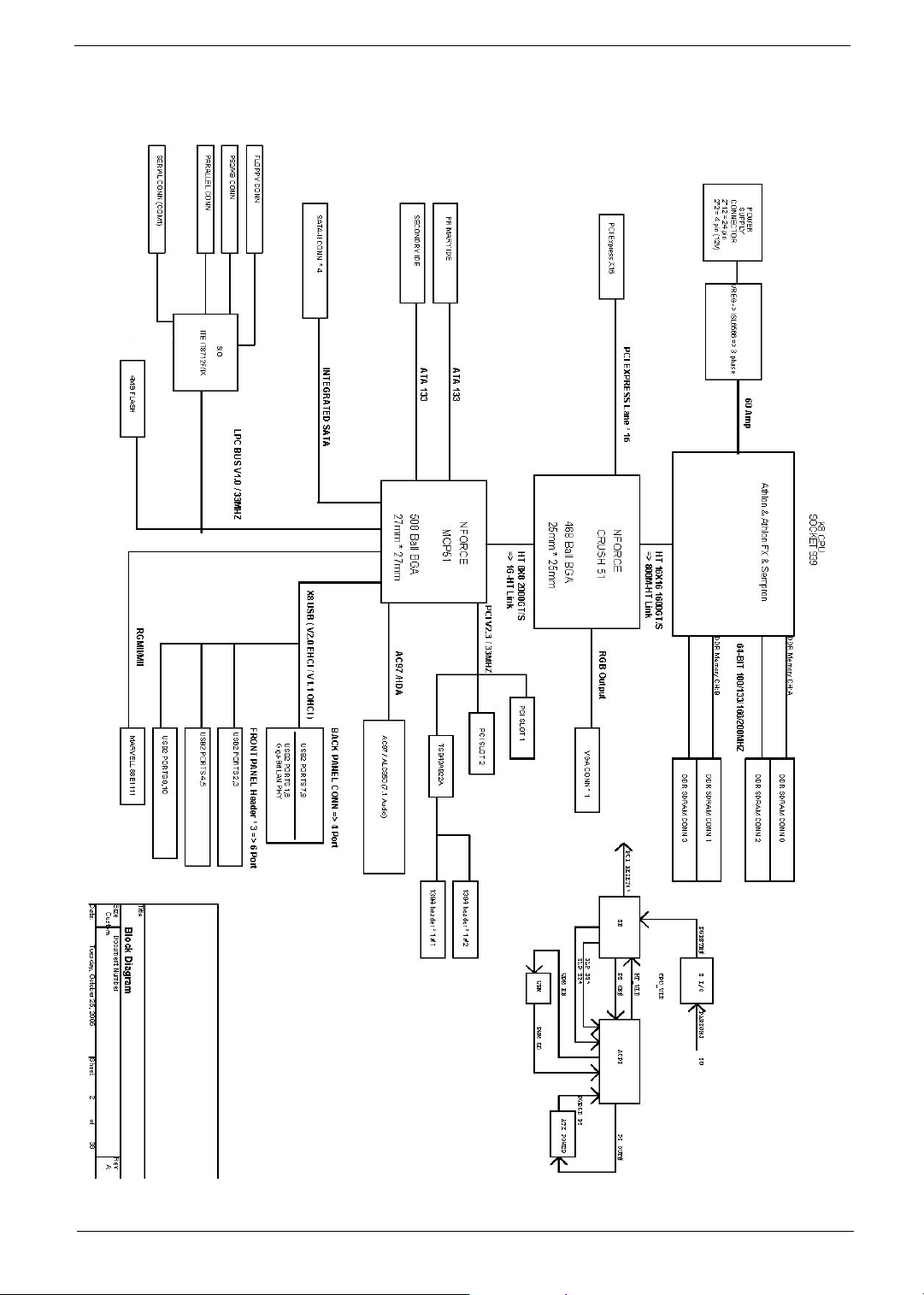
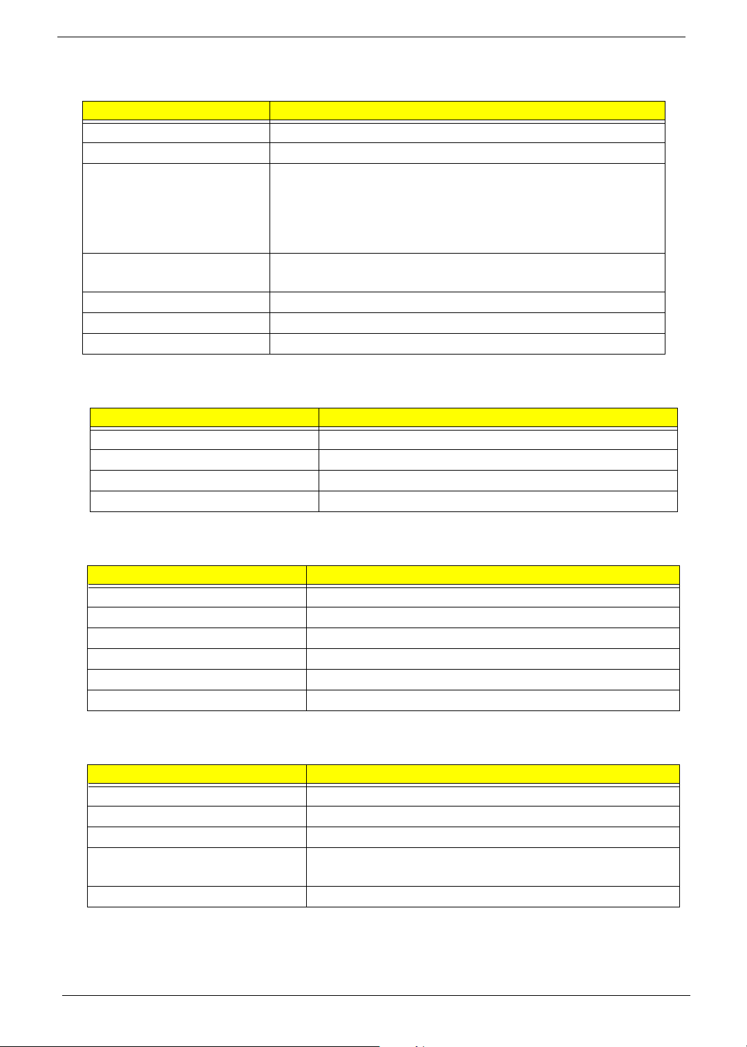
Block Diagram
Chapter 1 5
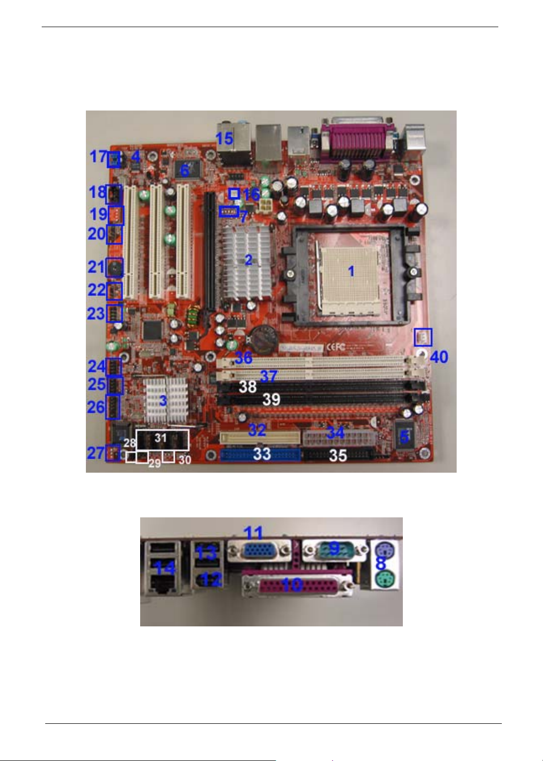
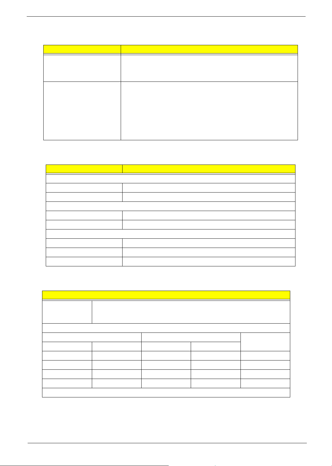
Main Board Placement
6 Chapter 1

No. Label Description
1U16 CPU socket
2 U15 North bridge
3 U26 South bridge
4 U2 Audio codec
5 U29 Super I/O controller
6 U3 LAN controller
7J4 TV OUT port
8 KB / MS Keyboard and mouse
9 COM1 COM1
10 PRT Printer
11 V GA VGA
12 1394_USB 1394 USB
13 USB USB port
14 NIC_USB Network and USB connector
15 Audio Audio
16 SYS_FAN System fan connector
17 F_Audio Front audio header
18 CD_IN CD IN
19 AUX_IN AUX IN
20 SPDIF_OUT SPDIF_OUT
21 BZ1 Buzzer
22 SPEAKER Speaker cable connector
23 F_1394 Front 1394 header
24 F_USB1 Front USB header
25 F_USB2 Front USB header
26 FP Front panel
27 TBL_EN Boot block jumper
28 CLR_CMOS Clear CMOS (password switch)
29 INTR Intruder
30 J2 Recovery
Chapter 1 7
No. Label Description
31
(from left
to right)
32 SIDE Secondary IDE port
33 PIDE Primary IDE port
34 Floppy Floppy drive connector
35 PWR1 24-pin power connector
36 DIMM1 DIMM socket 1
37 DIMM2 DIMM socket 2
38 DIMM3 DIMM socket 3
39 DIMM4 DIMM socket 4
40 CPU_FAN CPU fan connector
SATA_1 SATA_1
SATA_2 SATA_2
SATA_3 SATA_3
SATA_4 SATA_4
8 Chapter 1
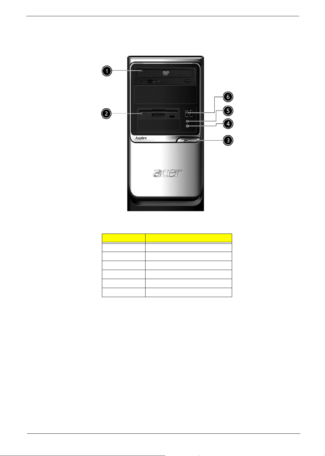
Aspire T160 Front Panel
No. Description
1 Optical device
2 Floppy drive
3 Power button
4 Microphone jack
5 Speaker/Headphone jack
6 USB ports
Chapter 1 9
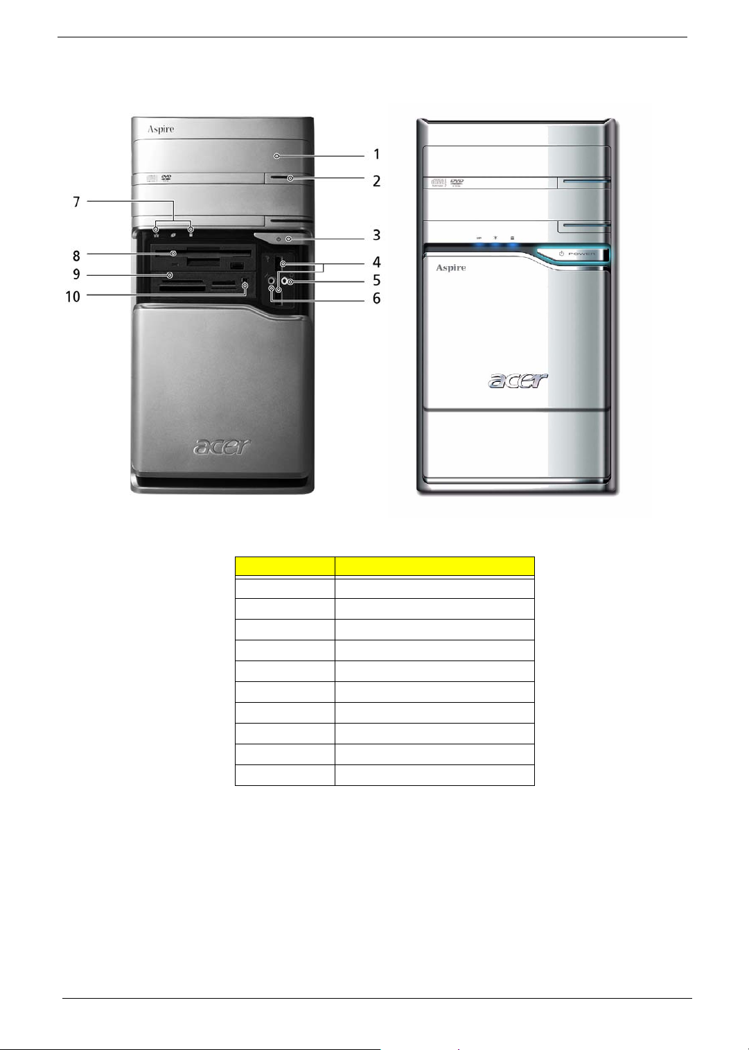
Aspire E360 Front Panel
No. Description
1 Optical driver
2 Optical drive eject button
3 Power button
4 USB ports
5 Speaker/Headphone jack
6 Microphone jack
7 Indicators
8 Floppy disk drive
9 Card reader
10 IEEE 1394 port
NOTE: The picture left is the front bezel with cover slided down.
10 Chapter 1
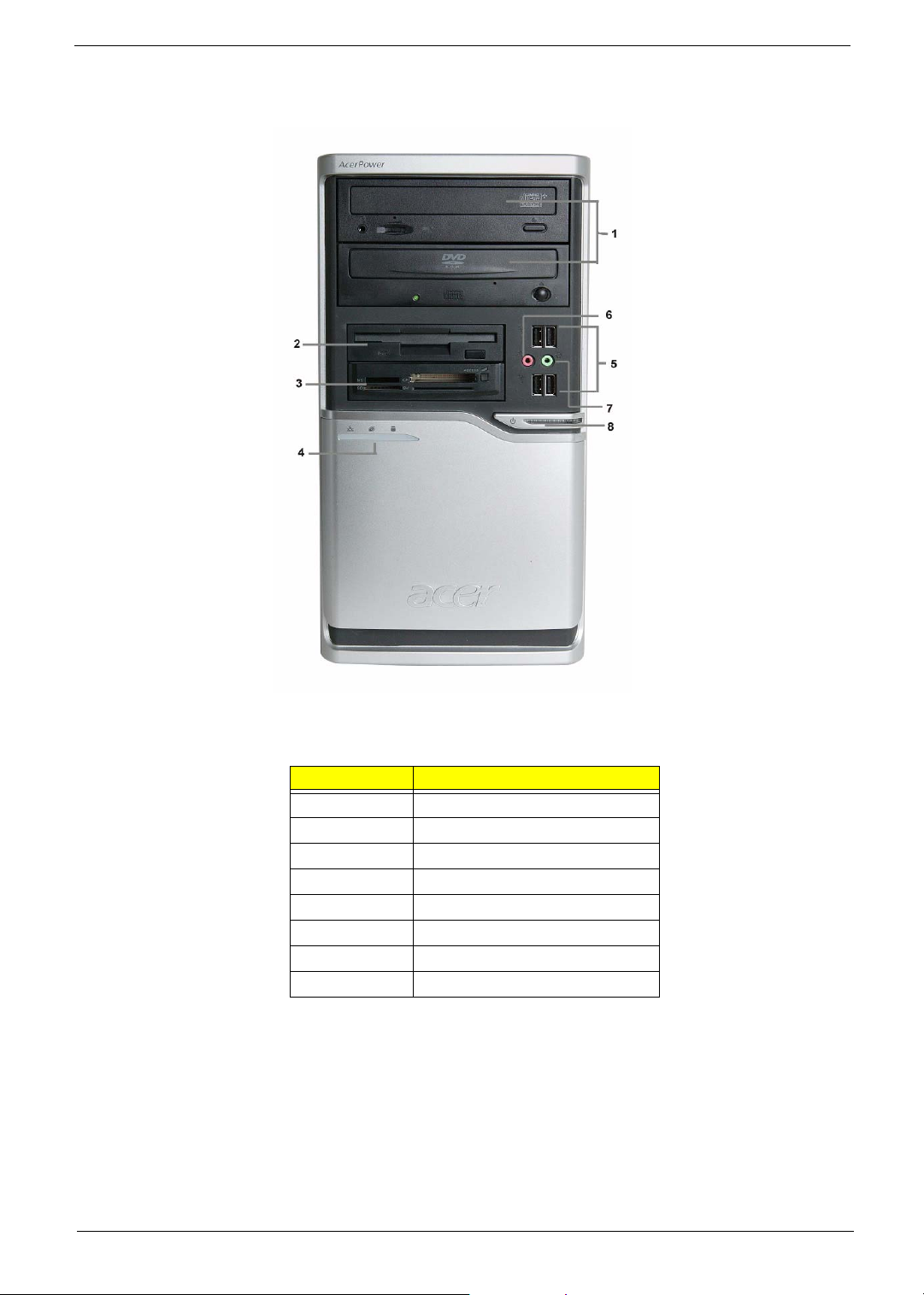
AcerPower M6 Front Panel
No. Description
1 Optical drive
2 Floppy disk drive
3 Card reader
4 Indicators
5 USB ports
6 Microphone jack
7 Speaker/Headphone jack
8 Power button
Chapter 1 11

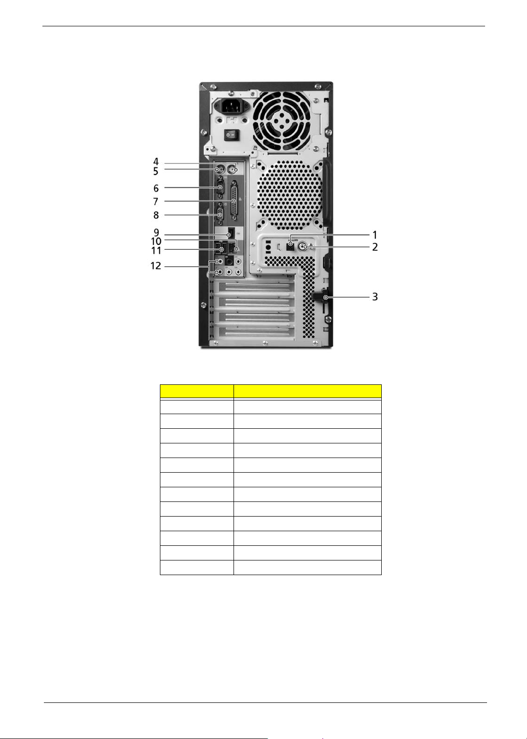
AcerPower M6 Rear Panel
No. Description
1 Power supply
2 Power cord socket
3 Voltage select switch
4 PS/2 Mouse port
5 PS/2 Keyboard port
6 Serial port
7 Printer port
8VGA port
9 USB Ports
10 RJ45 port
11 Audio jacks
12 Expansion slots
13 Lock handle
14 SPDIF port
15 Recovery switch holder
12 Chapter 1
Aspire T160/E360 Rear Panel
No. Description
1 SPDIF port
2 SPDIF port
3 Lock handle
4 PS/2 Mouse port
5 PS/2 Keyboard port
6 Serial port
7 Printer port
8VGA port
9 IEEE 1394 port
10 LAN port
11 USB ports
12 Audio jacks
Chapter 1 13
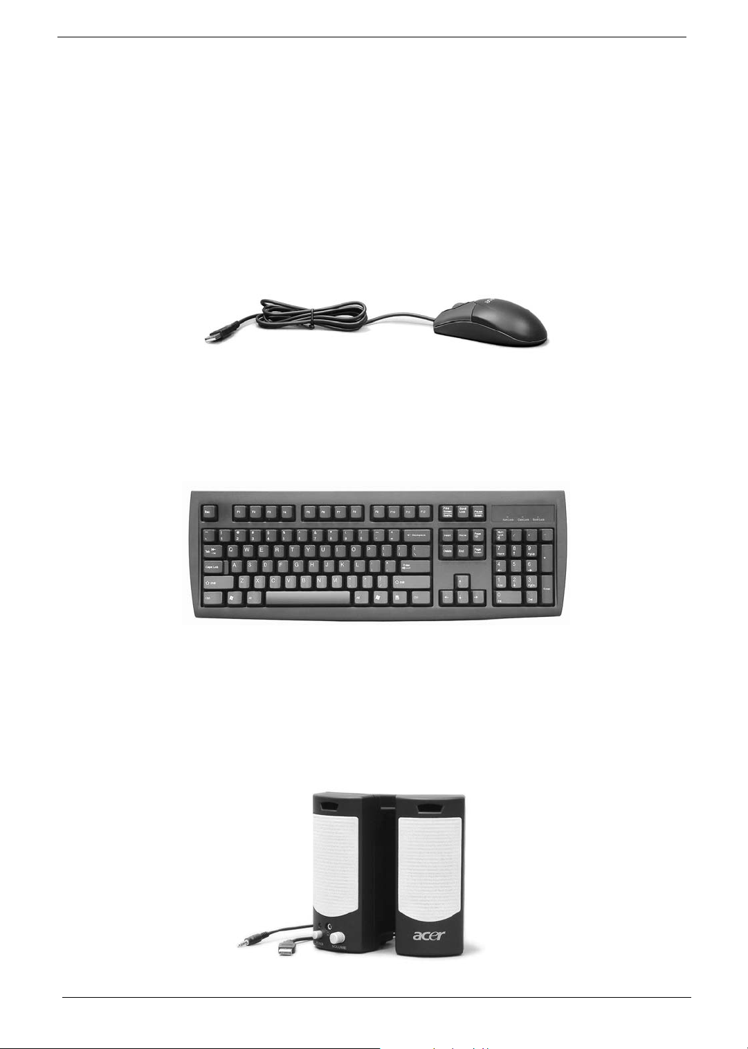
System Peripherals
Note:
The Aspire T160/E360 and AcerPower M6 computer consist of the system itself, and system peripherals, like
a mouse, keyboard and a set of speakers (optional). This section provides a brief description of the basic
system peripherals.
Mouse (PS/2 or USB, manufacturing option)
The included mouse is a standard two-button wheel mouse. Connect the mouse to the PS/2 mouse port or
USB port on the back panel of the system.
Keyboard (PS/2 or USB, manufacturing option)
Connect the keyboard to the PS/2 keyboard port or USB port on the back panel of the system.
Speakers
For system bundled with speakers, before powering on the system, connect the speaker cable to the audio out
(external speaker) port on the back panel of the system. Please refer to the included operating instructions for
more information.
NOTE: speakers are optional and the appearance might be different depending on the actual product.
14 Chapter 1

Acer eRecovery
Acer eRecovery is a tool to quickly backup and restore the system. Users can create and save a
backup of the current system configuration to hard drive, CD, or DVD.
Acer eRecovery consists of the following functions:
1. Create backup
2. Restore from backup
3. Create factory default image CD
4. Re-install bundled software without CD
5. Change Acer eRecovery password
Create Backup
Users can create and save backup images to hard drive, CD, or DVD.
1. Boot to Windows XP
2. Press <Alt>+<F10> to open the Acer eRecovery utility.
3. Enter the password to proceed. The default password is six zeros.
4. In the Acer eRecovery window, select Recovery settings and click Next
5. In the Recovery settings window, select Backup snapshot image and click Next.
6. Select the backup method.
T Use Backup to HDD to store the backup disc image on drive D:.
T Backup to optical device to store the backup disc image on CD or DVD (only available on
systems that include an optical disc burner).
7. After choosing the backup method, click Next.
Follow the instruction on screen to complete the process.
Restore from backup
Users can restore backup previously created (as stated in the Create backup section) from hard drive,
CD, or DVD.
1. Boot to Windows XP.
2. Press <Alt>+<F10> to open the Acer eRecovery utility.
3. Enter the password to proceed. The default password is six zeros.
4. In the Acer eRecovery window, select Recovery actions and click Next.
5. Select the desired restore action and follow the onscreen instructions to complete the restore process.
Create factory default image CD
When the System CD and Recovery CD are not available, you can create them by using this feature.
1. Boot to Windows XP.
2. Press <Alt>+<F10> to open the Acer eRecovery utility.
Chapter 1 15

3. Enter the password to proceed. The default password is six zeros.
4. In the Acer eRecovery window, select Recovery settings and click Next.
5. In the Recovery settings window, select Burn image to disc and click Next.
6. In the Burn image to disc window, select 01. Factory default image and click Next.
7. Follow the instructions on screen to complete the process.
Re-install bundled software without CD
Acer eRecovery stores pre-loaded software internally for easy driver and application re-installation.
1. Boot to Windows XP.
2. Press <Alt>+<F10> to open the Acer eRecovery utility.
3. Enter the password to proceed. The default password is six zeros.
4. In the Acer eRecovery window, select Recovery actions and click Next.
5. In the Recovery settings window, select Reinstall applications/drivers and click Next.
6. Select the desired driver/application and follow the instructions on screen to re-install.
At first launch, Acer eRecovery prepares all the needed software and may take few seconds to bring up the
software content window.
Change Password
Acer eRecovery and Acer disc-to-disc recovery are protected by a password that can be changed by
the user. Follow the steps below to change the password in Acer eRecovery.
1. Boot to Windows XP.
2. Press <Alt>+<F10> to open the Acer eRecovery utility.
3. Enter the password to proceed. The default password is six zeros.
4. In the Acer eRecovery window, select Recovery settings and click Next.
5. In the Recovery settings window, select Password: Change Acer eRecovery password and click Next.
6. Follow the instructions on screen to complete the process.
16 Chapter 1

Acer disc-to-disc recovery
Restore without a Recovery CD
This recovery process helps you restore the C: drive with the original software content that is installed when
you purchase your PC. Follow the steps below to rebuild your C: drive. (Your C: drive will be
reformatted and all data will be erased.) It is important to back up all data files before you use this option.
1. Restart the system.
2. While the Acer logo is showing, press <Alt>+<F10> at the same time to enter the recovery process.
3. The message "The system has password protection. Please enter 000000:" is displayed.
4. Enter six zeros and continue.
5. The Acer Recovery main page appears.
6. Use the arrow keys to scroll through the items (operating system versions) and press <Enter> to select.
Multilingual operating system installation
Follow the instructions to choose the operating system and language you prefer when you first power-on the
system.
1. Turn on the system.
2. Acer's multilingual operating system selection menu will pop-up automatically.
3. Use the arrow keys to scroll to the language version you want. Press <Enter> to confirm your selection.
4. The operating system and language you choose now will be the only option for future recovery
operations.
5. The system will install the operating system and language you choose.
Chapter 1 17
Hardware Specifications and Configurations
Major Chips
Item Specification
System Core Logic Nvidia C51G
MCP51
Super I/O Controller ITE 8712F
LAN Controller Marvell 88E1111
Memory Controller Nvidia C51G
IDE Controller MCP51
Audio Controller ALC850
VGA Controller Nvidia C51G
Keyboard Controller ITE 8712F
Processor
Item Specification
Type AMD Athlon 64 / Athlon 64x2 / Sempron
Slot Socket 939
Speed Depends on CPU, which is local configured
Bus Frequency
Voltage Processor voltage can be detected by any system without
HyperTransport
setting any jumper
TM
technology up to 1.0 GHz
BIOS
Item Specification
BIOS code programmer Phoenix Award
BIOS version R01-B1
BIOS ROM size 4MB
BIOS ROM package 32-pin PLCC package
Support protocol PCIX 1.0,PCI 2.2,APM 1.2,VESA/DPMS (VBE/PM V1.1),
SMBIOS 2.3, E-IDE 1.1, ACPI 1.0b,ESCD1.03, PnP 1.0a,
Bootable CD-ROM 1.0, USB 1.1~ USB 2.0, UHCI 1.0, ANSI
ATA 3.0 ATAPI
Boot from CD-ROM feature Yes
Support to LS-120 drive Yes
Support to BIOS boot block feature Yes
BIOS Password Control Yes
BIOS Hotkey
Hotkey Function Description
DEL Enter BIOS Setup Utility Press while the system is booting to
enter BIOS Setup Utility.
18 Chapter 1
System Memory
Item Specification
Memory Slot Number four slots
Memory Size per Slot 256 MB ~ 1GB
Supported Maximum Memory Size 4GB
Supported Memory Speed 400 MHz
Supported memory voltage 1.8 V
Support memory module package 240-pin DIMM
Support to parity check feature Yes
Support to Error Correction Code (ECC)
feature
Memory module combinations You can install memory modules in any combination as
VRM (Voltage Regulator Module)
Function VRM Specification Typical Voltage Power Source Maximum Output
CPU VRM VRM10.1 0.8375~1.6v 12 Voltage 101A
CPU VRM VRM 9.0 1.1-1.85 Voltage 12 Voltage 70A
Yes
long as they match the above specifications.
Cache Memory
Item Specification
First-Level Cache Configurations
Cache function control Enable/Disable by BIOS Setup
Second-Level Cache Configurations
The information below is only applicable to system installed with a Pentium 4 processor
Tag RAM Location On Processor
L2 Cache RAM Location On Processor
L2 Cache RAM type PBSRAM (Pipelined-burst Synchronous RAM)
L2 Cache RAM size Depends on CPU, which is local configured
L2 Cache RAM speed Full of the processor core clock frequency (Advanced Transfer Cache)
L2 Cache function control Enable/Disable by BIOS Setup
L2 Cache scheme Fixed in write-back
LAN Interface
Item Specification
LAN Controller
LAN Controller Resident Bus PCI Bus
LAN Port One RJ45 on board
Function Control Enable/Disable by BIOS Setup
Marvell 88E1111 GigaLAN Controller
Chapter 1 19
IDE Interface
Item Specification
IDE Controller MCP51
IDE Controller Resident Bus ATA133
Number of 40-pin PATA slot Two
Device Type Support: HDD, CD-ROM, CD-RW, DVD-ROM, Combo,
DVD burner
Transfer Rate Support: PIO 0/1/2/3/4
ATA Mode: 33/66/100/133
Number of STAT IDE slot Four
Device Type Support: HDD
LS-120 Supported
Bootable CD-ROM Supported
Function Control Enable/Disable by BIOS setup
Diskette Drive Interface
Item Specification
Diskette Drive Controller ITE 8712F
Diskette Drive Controller Resident Bus LPC Bus V1.0 / 33MHz
Supported Diskette Drive Formats 1.44MB, 2.88MB format and slim type diskette drive
Function Control Enable/Disable by BIOS Setup
Serial Port
Item Specification
Serial port controller ITE 8712F
Serial port controller resident bus LPC Bus V1.0 / 33MHz
Number of serial port One
Serial port location Rear Panel
16550 UART support Yes
Connector type 9-pin D-type female connector
USB Port
Item Specification
Universal HCI USB 2.0/1.1
Controller MCP51
Number of the connectors eight
Location Rear: four for AcerPower M6; two for Aspire T160/E360
Front: four for AcerPower M6; two for Aspire T160/E360
USB Class with support for legacy input devices
20 Chapter 1
Special Design Specifications
Thermal T Dynamic fan speed control by hardware monitor
T CPU over temperature (over 120
o
C) power off
protection
Power On / Wake-Up Event
T Power Button: S1/S3/S4/S5
T PS/2 Keyboard: S1/S3/S4
T USB Keyboard: S1/S3/S4
T RTC: S1/S5
T LAN: S1/S3/S5
T Modem (Ring): S1/S3/S5
Environment Requirements
Temperature
Operating +5°C ~ +35°C
Non-operating -20°C ~ +60°C (packed), -10°C ~ +60°C (un-packed)
Humidity
Operating 15% to 80% RH, non-condensing
Non-operating 10% to 90% RH, non-condensing at 40°C
Vibration
Operating (unpacked) 5 ~ 500Hz, 2.20g RMS random, 10 minutes per axis in all three axes
Non-operating (packed) 5 ~ 500Hz, 1.09g RMS random, one hour per axis in all three axes
Shock Operating Half sine, 2g 11m seconds
Drop Test
Definition The protection ability of packing & cushion must be capable of withstanding,
with no physical or functional damage, mechanical impact from height-specific
drops.
Test Standard
Package Cross Weight Drop Height Times of Drop
KGs lbs CM Inch
0~9.10~20763010
9.1~18.2 20~40 61 24 10
18.2~27.3 40~60 46 18 10
27.3~45.4 60~100 31 12 10
10 drops: one corner, three edges, six surfaces
Chapter 1 21
Loading...