


 Loading...
Acer Aspire 8942/8942G Series
Service Guide
Service guide files and updates are available on the ACER/CSD web; for more information, please refer to http://csd.acer.com.tw
PRINTED IN TAIWAN

Revision History
Please refer to the table below for the updates made on Acer Aspire 8942G service guides.
Date |
Chapter |
Updates |
|
|
|
|
|
|
|
|
|
|
|
|
II

Copyright
Copyright © 2009 by Acer Computer Incorporated. All rights reserved. No part of this publication may be reproduced, transmitted, transcribed, stored in a retrieval system, or translated into any language or computer language, in any form or by any means, electronic, mechanical, magnetic, optical, chemical, manual or otherwise, without the prior written permission of Acer Incorporated.
Disclaimer
The information in this guide is subject to change without notice.
Acer Incorporated makes no representations or warranties, either expressed or implied, with respect to the contents hereof and specifically disclaims any warranties of merchantability or fitness for any particular purpose. Any Acer Incorporated software described in this manual is sold or licensed "as is". Should the programs prove defective following their purchase, the buyer (and not Acer Incorporated, its distributor, or its dealer) assumes the entire cost of all necessary servicing, repair, and any incidental or consequential damages resulting from any defect in the software.
Acer is a registered trademark of Computer Corporation. Intel is a registered trademark of Intel Corporation.
Other brand and product names are trademarks and/or registered trademarks of their respective holders.
III

Conventions
The following conventions are used in this manual:
SCREEN MESSAGES |
Denotes actual messages that appear |
|
on screen. |
|
|
NOTE |
Gives bits and pieces of additional |
|
information related to the current |
|
topic. |
|
|
WARNING |
Alerts you to any damage that might |
|
result from doing or not doing specific |
|
actions. |
|
|
CAUTION |
Gives precautionary measures to |
|
avoid possible hardware or software |
|
problems. |
|
|
IMPORTANT |
Reminds you to do specific actions |
|
relevant to the accomplishment of |
|
procedures. |
|
|
IV

Preface
Before using this information and the product it supports, please read the following general information.
1.This Service Guide provides you with all technical information relating to the BASIC CONFIGURATION decided for Acer’s "global" product offering. To better fit local market requirements and enhance product competitiveness, your regional office MAY have decided to extend the functionality of a machine (e.g. add-on card, modem, or extra memory capability). These LOCALIZED FEATURES will NOT be covered in this generic service guide. In such cases, please contact your regional offices or the responsible personnel/channel to provide you with further technical details.
2.Please note WHEN ORDERING FRU PARTS, that you should check the most up-to-date information available on your regional web or channel. If, for whatever reason, a part number change is made, it will not be noted in the printed Service Guide. For ACER-AUTHORIZED SERVICE PROVIDERS, your Acer office may have a DIFFERENT part number code to those given in the FRU list of this printed Service Guide. You MUST use the list provided by your regional Acer office to order FRU parts for repair and service of customer machines.
V

VI

Table of Contents
System Specifications |
1 |
Features . . . . . . . . . . . . . . . . . . . . . . . . . . . . . . . . . . . . . . . . . . . . . . . . . . . . . . . . . . . .1
System Block Diagram . . . . . . . . . . . . . . . . . . . . . . . . . . . . . . . . . . . . . . . . . . . . . . . . .4
Front View . . . . . . . . . . . . . . . . . . . . . . . . . . . . . . . . . . . . . . . . . . . . . . . . . . . . . . .5
Closed Front View . . . . . . . . . . . . . . . . . . . . . . . . . . . . . . . . . . . . . . . . . . . . . . . . .7
Rear View . . . . . . . . . . . . . . . . . . . . . . . . . . . . . . . . . . . . . . . . . . . . . . . . . . . . . . .7
Left View . . . . . . . . . . . . . . . . . . . . . . . . . . . . . . . . . . . . . . . . . . . . . . . . . . . . . . . .8
Right View . . . . . . . . . . . . . . . . . . . . . . . . . . . . . . . . . . . . . . . . . . . . . . . . . . . . . . .9
Bottom View . . . . . . . . . . . . . . . . . . . . . . . . . . . . . . . . . . . . . . . . . . . . . . . . . . . .10
TouchPad Basics . . . . . . . . . . . . . . . . . . . . . . . . . . . . . . . . . . . . . . . . . . . . . . . .11
Using the Keyboard . . . . . . . . . . . . . . . . . . . . . . . . . . . . . . . . . . . . . . . . . . . . . . . . . .12
Key Types . . . . . . . . . . . . . . . . . . . . . . . . . . . . . . . . . . . . . . . . . . . . . . . . . . . . . .12
Windows Keys . . . . . . . . . . . . . . . . . . . . . . . . . . . . . . . . . . . . . . . . . . . . . . . . . .13
System Hotkeys . . . . . . . . . . . . . . . . . . . . . . . . . . . . . . . . . . . . . . . . . . . . . . . . .14
Hardware Specifications and Configurations . . . . . . . . . . . . . . . . . . . . . . . . . . . . . . .15
System Utilities |
31 |
BIOS Setup Utility . . . . . . . . . . . . . . . . . . . . . . . . . . . . . . . . . . . . . . . . . . . . . . . . . . . .31
Navigating the BIOS Utility . . . . . . . . . . . . . . . . . . . . . . . . . . . . . . . . . . . . . . . . .31
Information . . . . . . . . . . . . . . . . . . . . . . . . . . . . . . . . . . . . . . . . . . . . . . . . . . . . .32
Main . . . . . . . . . . . . . . . . . . . . . . . . . . . . . . . . . . . . . . . . . . . . . . . . . . . . . . . . . .33
Security . . . . . . . . . . . . . . . . . . . . . . . . . . . . . . . . . . . . . . . . . . . . . . . . . . . . . . . .34
Boot . . . . . . . . . . . . . . . . . . . . . . . . . . . . . . . . . . . . . . . . . . . . . . . . . . . . . . . . . . .37
Exit . . . . . . . . . . . . . . . . . . . . . . . . . . . . . . . . . . . . . . . . . . . . . . . . . . . . . . . . . . .38
BIOS Flash Utilities . . . . . . . . . . . . . . . . . . . . . . . . . . . . . . . . . . . . . . . . . . . . . . . . . . .39
DOS Flash Utility . . . . . . . . . . . . . . . . . . . . . . . . . . . . . . . . . . . . . . . . . . . . . . . . .40
WinFlash Utility . . . . . . . . . . . . . . . . . . . . . . . . . . . . . . . . . . . . . . . . . . . . . . . . . .42
Remove HDD/BIOS Password Utilities . . . . . . . . . . . . . . . . . . . . . . . . . . . . . . . . . . . .43
Machine Disassembly and Replacement |
49 |
Disassembly Requirements . . . . . . . . . . . . . . . . . . . . . . . . . . . . . . . . . . . . . . . . . . . |
.49 |
General Information . . . . . . . . . . . . . . . . . . . . . . . . . . . . . . . . . . . . . . . . . . . . . . . . . |
.50 |
Pre-disassembly Instructions . . . . . . . . . . . . . . . . . . . . . . . . . . . . . . . . . . . . . . |
.50 |
Disassembly Process . . . . . . . . . . . . . . . . . . . . . . . . . . . . . . . . . . . . . . . . . . . . . |
50 |
External Module Disassembly Process . . . . . . . . . . . . . . . . . . . . . . . . . . . . . . . . . . . |
51 |
External Modules Disassembly Flowchart . . . . . . . . . . . . . . . . . . . . . . . . . . . . . |
51 |
Removing the Battery Pack . . . . . . . . . . . . . . . . . . . . . . . . . . . . . . . . . . . . . . . . |
52 |
Removing the Express Dummy Card . . . . . . . . . . . . . . . . . . . . . . . . . . . . . . . . . |
53 |
Removing the SD Dummy Card . . . . . . . . . . . . . . . . . . . . . . . . . . . . . . . . . . . . . |
54 |
Removing the Lower Door . . . . . . . . . . . . . . . . . . . . . . . . . . . . . . . . . . . . . . . . . |
55 |
Removing the Optical Drive Module . . . . . . . . . . . . . . . . . . . . . . . . . . . . . . . . . . |
56 |
Removing the Primary Hard Disk Drive Module . . . . . . . . . . . . . . . . . . . . . . . . . |
58 |
Removing the Secondary Hard Disk Drive Module . . . . . . . . . . . . . . . . . . . . . . . |
60 |
Removing the DIMM Modules . . . . . . . . . . . . . . . . . . . . . . . . . . . . . . . . . . . . . . . |
62 |
Removing the TV Tuner Module . . . . . . . . . . . . . . . . . . . . . . . . . . . . . . . . . . . . . |
63 |
Removing the WLAN Module . . . . . . . . . . . . . . . . . . . . . . . . . . . . . . . . . . . . . . . |
65 |
Main Unit Disassembly Process . . . . . . . . . . . . . . . . . . . . . . . . . . . . . . . . . . . . . . . . . |
67 |
Upper Cover Disassembly Flowchart . . . . . . . . . . . . . . . . . . . . . . . . . . . . . . . . . |
67 |
Lower Cover Disassembly Flowchart . . . . . . . . . . . . . . . . . . . . . . . . . . . . . . . . . |
68 |
Removing the Keyboard . . . . . . . . . . . . . . . . . . . . . . . . . . . . . . . . . . . . . . . . . . . |
69 |
Removing the Switch Cover . . . . . . . . . . . . . . . . . . . . . . . . . . . . . . . . . . . . . . . . |
71 |
Removing the Power Board . . . . . . . . . . . . . . . . . . . . . . . . . . . . . . . . . . . . . . . . |
73 |
Removing the LCD Module . . . . . . . . . . . . . . . . . . . . . . . . . . . . . . . . . . . . . . . . . |
74 |
Removing the Upper Cover . . . . . . . . . . . . . . . . . . . . . . . . . . . . . . . . . . . . . . . . |
77 |
VII

Table of Contents |
|
Removing the Launch Board . . . . . . . . . . . . . . . . . . . . . . . . . . . . . . . . . . . . . |
. .81 |
Removing the Volume Control Board . . . . . . . . . . . . . . . . . . . . . . . . . . . . . . . |
. .82 |
Removing the Power Saving Board FFC . . . . . . . . . . . . . . . . . . . . . . . . . . . . . |
.84 |
Removing the Media Board . . . . . . . . . . . . . . . . . . . . . . . . . . . . . . . . . . . . . . . |
.85 |
Removing the TouchPad Lock Board . . . . . . . . . . . . . . . . . . . . . . . . . . . . . . . . |
.87 |
Removing the Finger Print Reader Bracket . . . . . . . . . . . . . . . . . . . . . . . . . . . |
.89 |
Removing the TouchPad Board . . . . . . . . . . . . . . . . . . . . . . . . . . . . . . . . . . . . |
.90 |
Removing the RTC Battery . . . . . . . . . . . . . . . . . . . . . . . . . . . . . . . . . . . . . . . . |
.93 |
Removing the Bluetooth Board . . . . . . . . . . . . . . . . . . . . . . . . . . . . . . . . . . . . . |
.94 |
Removing the USB Board . . . . . . . . . . . . . . . . . . . . . . . . . . . . . . . . . . . . . . . . . |
.96 |
Removing the Power Saving Board . . . . . . . . . . . . . . . . . . . . . . . . . . . . . . . . . |
.98 |
Removing the Mainboard . . . . . . . . . . . . . . . . . . . . . . . . . . . . . . . . . . . . . . . . . |
.99 |
Removing the Kensington Lock Bracket . . . . . . . . . . . . . . . . . . . . . . . . . . . . . . |
101 |
Removing the TV Tuner Antenna . . . . . . . . . . . . . . . . . . . . . . . . . . . . . . . . . . . |
102 |
Removing the Subwoofer . . . . . . . . . . . . . . . . . . . . . . . . . . . . . . . . . . . . . . . . . |
103 |
Removing the Hinge Supports . . . . . . . . . . . . . . . . . . . . . . . . . . . . . . . . . . . . . |
105 |
Removing the Speaker Module . . . . . . . . . . . . . . . . . . . . . . . . . . . . . . . . . . . . . |
106 |
Removing the Thermal Module . . . . . . . . . . . . . . . . . . . . . . . . . . . . . . . . . . . . . |
107 |
Removing the Graphics Card Heatsink . . . . . . . . . . . . . . . . . . . . . . . . . . . . . . . |
108 |
Removing the Graphics Card . . . . . . . . . . . . . . . . . . . . . . . . . . . . . . . . . . . . . . |
109 |
Removing the CPU . . . . . . . . . . . . . . . . . . . . . . . . . . . . . . . . . . . . . . . . . . . . . . |
110 |
LCD Module Disassembly Process . . . . . . . . . . . . . . . . . . . . . . . . . . . . . . . . . . . . . |
111 |
Standard Bezel LCD Module Disassembly Flowchart . . . . . . . . . . . . . . . . . . . |
111 |
Removing the Standard LCD Bezel . . . . . . . . . . . . . . . . . . . . . . . . . . . . . . . . . |
112 |
Removing the LCD Panel . . . . . . . . . . . . . . . . . . . . . . . . . . . . . . . . . . . . . . . . . |
115 |
Removing the Camera Board . . . . . . . . . . . . . . . . . . . . . . . . . . . . . . . . . . . . . . |
117 |
Removing the LCD Brackets and FPC Cable . . . . . . . . . . . . . . . . . . . . . . . . . . |
118 |
Flush Bezel LCD Module Disassembly Flowchart . . . . . . . . . . . . . . . . . . . . . . |
120 |
Removing the Flush LCD Bezel Cap . . . . . . . . . . . . . . . . . . . . . . . . . . . . . . . . |
121 |
Removing the Flush LCD Bezel . . . . . . . . . . . . . . . . . . . . . . . . . . . . . . . . . . . . |
123 |
Removing the LCD Panel . . . . . . . . . . . . . . . . . . . . . . . . . . . . . . . . . . . . . . . . . |
125 |
Removing the Camera Board . . . . . . . . . . . . . . . . . . . . . . . . . . . . . . . . . . . . . . |
127 |
Removing the LCD Brackets and FPC Cable . . . . . . . . . . . . . . . . . . . . . . . . . . |
128 |
LCD Module Reassembly Procedure . . . . . . . . . . . . . . . . . . . . . . . . . . . . . . . . . . . . |
130 |
Standard Bezel LCD Module Reassembly—LCD Panel . . . . . . . . . . . . . . . . . . |
130 |
Replacing the LCD Bezel . . . . . . . . . . . . . . . . . . . . . . . . . . . . . . . . . . . . . . . . . |
134 |
Flush Bezel LCD Module Reassembly—LCD Panel . . . . . . . . . . . . . . . . . . . . |
136 |
Replacing the LCD Bezel . . . . . . . . . . . . . . . . . . . . . . . . . . . . . . . . . . . . . . . . . |
140 |
Replacing the Flush LCD Bezel Cap . . . . . . . . . . . . . . . . . . . . . . . . . . . . . . . . |
142 |
Main Module Reassembly Procedure . . . . . . . . . . . . . . . . . . . . . . . . . . . . . . . . . . . . |
144 |
Replacing the CPU . . . . . . . . . . . . . . . . . . . . . . . . . . . . . . . . . . . . . . . . . . . . . . |
144 |
Replacing the Graphics Card . . . . . . . . . . . . . . . . . . . . . . . . . . . . . . . . . . . . . . |
145 |
Replacing the Graphics Card Heatsink . . . . . . . . . . . . . . . . . . . . . . . . . . . . . . . |
146 |
Replacing the Thermal Module . . . . . . . . . . . . . . . . . . . . . . . . . . . . . . . . . . . . . |
147 |
Replacing the Speaker Module . . . . . . . . . . . . . . . . . . . . . . . . . . . . . . . . . . . . . |
148 |
Replacing the Hinge Supports . . . . . . . . . . . . . . . . . . . . . . . . . . . . . . . . . . . . . |
149 |
Replacing the Subwoofer . . . . . . . . . . . . . . . . . . . . . . . . . . . . . . . . . . . . . . . . . |
150 |
Removing the TV Tuner Antenna . . . . . . . . . . . . . . . . . . . . . . . . . . . . . . . . . . . |
152 |
Replacing the Kensington Lock Bracket . . . . . . . . . . . . . . . . . . . . . . . . . . . . . . |
153 |
Replacing the Mainboard . . . . . . . . . . . . . . . . . . . . . . . . . . . . . . . . . . . . . . . . . |
154 |
Replacing the Power Saving Board . . . . . . . . . . . . . . . . . . . . . . . . . . . . . . . . . |
155 |
Replacing the USB Board . . . . . . . . . . . . . . . . . . . . . . . . . . . . . . . . . . . . . . . . . |
156 |
Replacing the Bluetooth Board . . . . . . . . . . . . . . . . . . . . . . . . . . . . . . . . . . . . . |
158 |
Replacing the RTC Battery . . . . . . . . . . . . . . . . . . . . . . . . . . . . . . . . . . . . . . . . |
160 |
Replacing the TouchPad Board . . . . . . . . . . . . . . . . . . . . . . . . . . . . . . . . . . . . |
161 |
VIII

|
Table of Contents |
Replacing the Finger Print Reader Bracket . . |
. . . . . . . . . . . . . . . . . . . . . . . . .164 |
Replacing the TouchPad Lock Board . . . . . . . |
. . . . . . . . . . . . . . . . . . . . . . . . .165 |
Replacing the Media Board . . . . . . . . . . . . . . . |
. . . . . . . . . . . . . . . . . . . . . . . . .167 |
Replacing the Power Saving Board FFC . . . . |
. . . . . . . . . . . . . . . . . . . . . . . . .168 |
Replacing the Volume Control Board . . . . . . . |
. . . . . . . . . . . . . . . . . . . . . . . . .169 |
Replacing the Launch Board . . . . . . . . . . . . . . |
. . . . . . . . . . . . . . . . . . . . . . . . .171 |
Replacing the Upper Case . . . . . . . . . . . . . . . |
. . . . . . . . . . . . . . . . . . . . . . . . .172 |
Replacing the LCD Module . . . . . . . . . . . . . . . |
. . . . . . . . . . . . . . . . . . . . . . . . .175 |
Replacing the Power Board . . . . . . . . . . . . . . |
. . . . . . . . . . . . . . . . . . . . . . . . .179 |
Replacing the Switch Cover . . . . . . . . . . . . . . |
. . . . . . . . . . . . . . . . . . . . . . . . .180 |
Replacing the Keyboard . . . . . . . . . . . . . . . . . |
. . . . . . . . . . . . . . . . . . . . . . . . .182 |
External Module Reassembly Instructions . . . . . . . |
. . . . . . . . . . . . . . . . . . . . . . . . .184 |
Replacing the WLAN Module . . . . . . . . . . . . . |
. . . . . . . . . . . . . . . . . . . . . . . . .184 |
Replacing the TV Tuner Module . . . . . . . . . . . |
. . . . . . . . . . . . . . . . . . . . . . . . .185 |
Replacing the DIMM Modules . . . . . . . . . . . . . |
. . . . . . . . . . . . . . . . . . . . . . . . .186 |
Replacing the Hard Disk Drive Module . . . . . . |
. . . . . . . . . . . . . . . . . . . . . . . . .186 |
Replacing the ODD Module . . . . . . . . . . . . . . |
. . . . . . . . . . . . . . . . . . . . . . . . .187 |
Replacing the Lower Covers . . . . . . . . . . . . . . |
. . . . . . . . . . . . . . . . . . . . . . . . .188 |
Replacing the SD Dummy Card . . . . . . . . . . . |
. . . . . . . . . . . . . . . . . . . . . . . . .189 |
Replacing the Battery . . . . . . . . . . . . . . . . . . . |
. . . . . . . . . . . . . . . . . . . . . . . . .189 |
Troubleshooting |
191 |
Common Problems . . . . . . . . . . . . . . . . . . . . . . . . . . . . . . . . . . . . . . . . . . . . . . . . . .191
Power On Issue . . . . . . . . . . . . . . . . . . . . . . . . . . . . . . . . . . . . . . . . . . . . . . . .192
No Display Issue . . . . . . . . . . . . . . . . . . . . . . . . . . . . . . . . . . . . . . . . . . . . . . . .193
Random Loss of BIOS Settings . . . . . . . . . . . . . . . . . . . . . . . . . . . . . . . . . . . .194
LCD Failure . . . . . . . . . . . . . . . . . . . . . . . . . . . . . . . . . . . . . . . . . . . . . . . . . . . .195
Built-In Keyboard Failure . . . . . . . . . . . . . . . . . . . . . . . . . . . . . . . . . . . . . . . . .196
TouchPad Failure . . . . . . . . . . . . . . . . . . . . . . . . . . . . . . . . . . . . . . . . . . . . . . .197
Internal Speaker Failure . . . . . . . . . . . . . . . . . . . . . . . . . . . . . . . . . . . . . . . . . .198
Internal Microphone Failure . . . . . . . . . . . . . . . . . . . . . . . . . . . . . . . . . . . . . . .199
HDD Not Operating Correctly . . . . . . . . . . . . . . . . . . . . . . . . . . . . . . . . . . . . . .200
USB (Right Up/Down Side) Failure . . . . . . . . . . . . . . . . . . . . . . . . . . . . . . . . . .201
Other Failures . . . . . . . . . . . . . . . . . . . . . . . . . . . . . . . . . . . . . . . . . . . . . . . . . .201
Intermittent Problems . . . . . . . . . . . . . . . . . . . . . . . . . . . . . . . . . . . . . . . . . . . . . . . .201
Undetermined Problems . . . . . . . . . . . . . . . . . . . . . . . . . . . . . . . . . . . . . . . . . . . . . .202
Post Codes . . . . . . . . . . . . . . . . . . . . . . . . . . . . . . . . . . . . . . . . . . . . . . . . . . . . . . . .203
Chipset POST Codes . . . . . . . . . . . . . . . . . . . . . . . . . . . . . . . . . . . . . . . . . . . .203
Jumper and Connector Locations |
207 |
Top View . . . . . . . . . . . . . . . . . . . . . . . . . . . . . . . . . . . . . . . . . . . . . . . . . . . . . |
.207 |
Bottom View . . . . . . . . . . . . . . . . . . . . . . . . . . . . . . . . . . . . . . . . . . . . . . . . . . |
.208 |
Clearing Password Check and BIOS Recovery . . . . . . . . . . . . . . . . . . . . . . . . . . . |
.209 |
Clearing Password Check . . . . . . . . . . . . . . . . . . . . . . . . . . . . . . . . . . . . . . . . |
.209 |
BIOS Recovery by Crisis Disk . . . . . . . . . . . . . . . . . . . . . . . . . . . . . . . . . . . . |
.210 |
FRU (Field Replaceable Unit) List |
211 |
Acer 8942G Exploded Diagrams . . . . . . . . . . . . . . . . . . . . . . . . . . . . . . . . . . . . . . .212
Main Chassis . . . . . . . . . . . . . . . . . . . . . . . . . . . . . . . . . . . . . . . . . . . . . . . . . .212
LCD Assembly . . . . . . . . . . . . . . . . . . . . . . . . . . . . . . . . . . . . . . . . . . . . . . . . .214
Acer Aspire 8942G FRU List . . . . . . . . . . . . . . . . . . . . . . . . . . . . . . . . . . . . . . . . . .216
Screw List . . . . . . . . . . . . . . . . . . . . . . . . . . . . . . . . . . . . . . . . . . . . . . . . . . . . .226
Model Definition and Configuration |
228 |
Aspire 8942G Series . . . . . . . . . . . . . . . . . . . . . . . . . . . . . . . . . . . . . . . . . . . . . . . . .228
IX

Table of Contents |
|
Test Compatible Components |
291 |
Microsoft® Windows® 7 Environment Test . . . . . . . . . . . . . . . . . . . . . . . . . . . . . . |
.292 |
Online Support Information |
295 |
Index |
297 |
X
Chapter 1
System Specifications
Features
Below is a brief summary of the computer’s many features:
NOTE: Items marked with * denote only selected models.
Operating System
•Genuine Windows 7®
Platform
•Intel® Core™ i7 processor*
•Intel® Core™ i5 processor*
•Intel® Core™ i3 processor*
•Intel® HM55 Express Chipset
•ATI Mobility Radeon™ HD 5650 or 5850
System Memory
•Dual-Channel SDRAM support
•Up to 4 GB of DDR3 1066 MHz memory, upgradeable to 8 GB using two soDIMM modules
Display
•18.4” TFT LCD
•Resolution: 1920 x 1080 Full HD
•16:9 aspect ratio
Graphics
•AMD Broadway-Pro or Madison-Pro
Storage subsystem
•2.5" hard disk drive
•Optical drive options:
•Blu-ray Disc™ Writer/DVD-Super Multi doublelayer drive*
•Blu-ray Disc™/DVD-Super Multi double-layer drive*
•DVD-Super Multi double-layer drive*
•Multi-in-1 card reader
Chapter 1 |
1 |

Audio
•Dolby®-optimized surround sound system with five built-in stereo speakers and one subwoofer
•True5.1-channel surround sound output
•High-definition audio support
•S/PDIF (Sony/Philips Digital Interface) support for digital speakers
•MS-Sound compatible
•Acer Purezone technology with two built-in stereo microphones
Dimensions and Weight
•440 (W) x 295 (D) x 31/43.8 (H) mm (17.34 x 11.62 x 1.22/1.73 inches)
•4.6 kg (10.1 lbs.) with 8-cell battery
Communication
•Acer Video Conference, featuring:
•Integrated Acer Crystal Eye webcam*
•Acer PureZone technology*
•WLAN:
•Intel® Centrino® Ultimate-N 6300 802.11a/g/n*
•Intel® Centrino® Advanced-N 6200 802.11a/g/n*
•Intel® Centrino® Wireless-N 1000 802.11b/g/n*
•Acer InviLink™ Nplify™ 802.11b/g/n*
•Acer InviLink™ 802.11b/g*
•WPAN: Bluetooth® 2.1+Enhanced Data Rate (EDR)*
•LAN: Gigabit Ethernet; Wake-on-LAN ready
Privacy control
•Acer Bio-Protection fingerprint solution*
•BIOS user, supervisor, HDD passwords
•Kensington lock slot
Power subsystem
•ACPI 3.0
•71 W 4800 mAh battery
•3-pin 120 W AC adapter
•ENERGY STAR®*
Special keys and controls
•103-/104-/107-key keyboard
•Touchpad pointing device
2 |
Chapter 1 |

I/O interface
•ExpressCard®/54 slot
•Acer Bio-Protection fingerprint reader*
•Multi-in-1 card reader (SD/MMC/MS/MS PRO/xD)
•USB 2.0 port
•IEEE 1394 port
•HDMI™ port with HDCP support
•DISPLAY port
•eSATA port
•External display (VGA) port
•Consumer infrared (CIR) port
•RF-in jack*
•Headphones/speaker/line-out jack with S/PDIF support
•Microphone-in jack
•Line-in jack
•Ethernet (RJ-45) port
•DC-in jack for AC adapter
Environment
•Temperature:
•Operating: 5 °C to 35 °C
•Non-operating: -20 °C to 65 °C
•Humidity (non-condensing):
•Operating: 20% to 80%
•Non-operating: 20% to 80%
Chapter 1 |
3 |

System Block Diagram
|
|
|
|
|
|
|
|
|
|
|
|
|
|
|
|
|
|
|
|
|
|
|
|
|
|
|
|
|
|
|
|
|
|
|
|
|
|
|
|
|
|
|
|
|
|
|
|
|
|
|
|
|
|
|
|
|
|
|
|
|
|
|
|
|
|
|
|
|
|
|
|
|
|
|
|
|
|
|
|
|
|
|
|
|
|
|
|
|
|
|
|
|
|
|
|
|
|
|
|
|
|
|
|
|
|
|
|
|
|
|
|
|
|
|
|
|
|
|
|
|
|
|
|
|
|
|
|
|
|
|
|
|
|
|
|
GPU CORE PWR |
CHARGER |
|
|||||||
|
|
|
|
|
|
|
|
|
|
|
|
|
|
|
|
|
|
|
|
|
|
|
|
|
|
|
|
|
|
|
|
|
|
|
|
|
|
|
|
|
|
|
|
|
|
|
|
|
|
|
|
|
|
|
|
|
|
|
|
|
|
|
ISL6264 |
ISL88731 |
|
|||||||
|
|
|
|
|
|
|
|
|
|
|
|
|
|
|
|
|
|
|
|
|
|
|
|
|
|
|
|
|
|
|
|
|
|
|
|
|
|
|
|
|
|
|
|
|
|
|
|
|
|
|
|
|
|
|
|
|
|
|
|
|
|
|
|
|
|
|
|
|||||
|
|
|
|
|
|
|
|
|
|
|
|
|
|
|
|
|
|
|
|
|
|
|
|
|
|
|
|
|
|
|
|
|
|
|
|
|
|
|
|
|
|
|
|
|
|
|
|
|
|
|
|
|
|
|
|
|
|
|
|
|
|
|
GPU IO PWR |
3/5V SYS PWR |
|
|||||||
|
|
|
|
|
|
|
|
|
|
|
|
|
|
|
|
|
|
|
|
|
|
|
|
|
|
|
|
|
|
|
|
|
|
|
|
|
|
|
|
|
|
|
|
|
|
|
|
|
|
|
|
|
|
|
|
|
|
|
|
|
|
|
ISL62827 |
ISL6237 |
|
|||||||
|
|
|
|
|
|
|
|
|
|
|
|
|
|
|
|
|
|
|
|
|
|
|
|
|
|
|
|
|
|
|
|
|
|
|
|
|
|
|
|
|
|
|
|
|
|
|
|
|
|
|
|
|
|
|
|
|
|
|
|
|
|
|
|
|
|
|
|
|||||
|
|
|
|
|
|
|
|
|
|
|
|
|
|
|
|
|
|
|
|
|
|
|
|
|
|
|
|
|
|
|
|
|
|
|
|
|
|
|
|
|
|
|
|
|
|
|
|
|
|
|
|
|
|
|
|
|
|
|
|
|
|
|
DISCHARGER |
CPU CORE PWR |
|
|||||||
|
|
|
|
|
|
|
|
|
|
|
|
|
|
|
|
|
|
|
|
|
|
|
|
|
|
|
|
|
|
|
|
|
|
|
|
|
|
|
|
|
|
|
|
|
|
|
|
|
|
|
|
|
|
|
|
|
|
|
|
|
|
|
+3V,+ 5V,+1.5V,+1.05V,+1.1V_VTT |
ISL62882 |
|
|||||||
|
|
|
|
|
|
|
|
|
|
|
CLOCK GENERATOR |
|
|
BCLK: 133MHz |
|
|
|
|
|
|
intel |
|
|
|
|
|
|
|
|
Fan Driver |
|
|
|
|
|
|
|
|
|
|
|
|
|
|
|
|
|
|
|
|
|
|
||||||||||||||||||||
|
|
|
|
|
|
|
|
|
|
|
|
|
|
|
|
|
|
|
DPLL_REF_SSCLK: 120MHz |
|
|
|
|
|
|
|
|
|
|
|
|
|
|
|
|
|
|
|
|
|
|
|
|
|
|
|
|
|
|
|
|
|
|
|
|
|
|
ARD: 1.05V |
|
|||||||||||||
|
|
|
|
|
|
|
|
|
|
|
|
|
|
|
|
|
|
|
PEG_CLK: 100MHz |
|
|
|
|
|
|
|
|
|
|
|
|
|
|
|
|
|
|
|
|
|
|
|
|
|
|
|
|
|
|
|
|
|
|
|
|
|
|
|
|
|
|
|
|
|
|
|
|
|||||
|
|
|
|
|
|
|
|
|
|
|
SELGO: SLG8SP585V |
|
|
|
|
|
|
|
|
|
|
|
|
<MCH Processor> |
|
|
|
|
|
|
(PWM Type) |
|
|
|
|
|
|
|
|
|
|
|
|
+1.0V/+1.5V |
CPU VTT CFD: 1.1V |
|
||||||||||||||||||||||||||
|
|
|
|
|
|
X'TAL |
|
|
|
|
|
|
|
|
|
|
|
|
|
|
|
|
|
|
|
|
|
|
|
|
|
|
|
|
|
|
|
|
|
|
|
|
|
|
|
|
|
|
G93334 + Linear |
UP61111AQDD |
|
|||||||||||||||||||||
|
|
|
|
|
|
14.318MHz |
|
|
|
|
|
|
|
|
|
|
|
|
|
|
|
MEMORY |
|
|
|
|
|
|
|
|
|
|
|
|
|
|
|
|
|
|
|
|
|
|
|
|
|
|
|
|
|
|
|
|
|
|
|
|
|
|
|
|
|
|
|
|
|
|
||||
|
|
|
|
|
|
|
|
|
|
|
|
|
|
|
|
|
|
|
|
|
|
|
|
|
|
|
|
|
|
|
|
|
|
|
|
|
|
|
|
|
|
|
|
|
|
|
|
|
|
|
|
|
|
|
|
|
|
|
|
|
|
|
|
|
|
|
|
|
|
|
||
|
|
|
|
|
|
|
|
|
|
|
|
|
|
|
|
|
|
|
|
|
|
|
|
|
Arrandale (SG)* |
|
|
|
|
|
|
|
|
CPU & PCH |
|
|
|
|
|
|
|
|
|
|
|
|
CPU VGFX_AXG |
VTT 1.05V |
|
|||||||||||||||||||||||
|
|
|
|
|
|
|
|
|
|
|
DDR III |
|
|
|
|
Dual Channel |
|
|
|
|
|
|
|
|
|
|
|
|
|
|
|
|
|
|
|
|
|
|
|
|
|
|
|
|
ISL62881 |
UP61111AQDD |
|
|||||||||||||||||||||||||
|
|
|
|
|
|
|
|
|
|
|
|
|
|
|
|
|
|
|
|
|
|
|
|
|
XDP Conn. |
|
|
|
|
|
|
|
|
|
|
|
|
|
|
|
|
|
|
|
|
|
|
|||||||||||||||||||||||||
|
|
|
|
|
|
|
|
|
|
|
|
SO-DIMM 0 |
|
|
|
|
800/ 1066 MHz |
SYSTEM |
Clarksfield (Discrete) |
|
|
|
|
|
|
|
|
|
|
|
|
|
|
|
|
|
|
|
|
|
|
|
THERMAL |
DDR3 PWR |
|
|||||||||||||||||||||||||||
|
|
|
|
|
|
|
|
|
|
|
|
|
|
|
|
|
|
|
|
|
|
|
|
|
|
|
|
|
|
|
|
|
|
|
|
|
|
|
|
|
|
|
|
|
|
|
|
|
|
|
|
|
|
|
|
|
|
|
||||||||||||||
|
|
|
|
|
|
|
|
|
|
|
|
SO-DIMM 1 |
|
|
|
|
800 MT/s 1066 MT/s |
|
|
|
|
(37.5mm X 37.5mm) |
|
|
|
|
|
|
|
|
|
|
|
|
|
|
|
|
|
|
|
|
|
|
|
|
|
|
PROTECTION |
|
|
TPS5116 |
|
|||||||||||||||||||
|
|
|
|
|
|
|
|
|
|
|
|
|
|
|
|
|
|
|
|
|
|
|
|
|
DDR |
|
|
|
|
rPGA 989 |
PCI-E |
|
|
PCIE |
|
|
|
|
|
|
|
|
|
|
|
|
|
|
|
|
|
|
|
|
|
|
|
|
|
|
|
|
||||||||||
|
|
|
|
|
|
|
|
|
|
|
|
|
|
|
|
|
|
|
|
|
|
|
|
|
|
|
|
|
|
|
|
|
|
|
|
|
|
|
|
|
|
|
|
|
|
|
|
|
|
|
|
|
|
|
|
|
|
|
|
|
|
|
|
|
||||||||
|
|
|
|
|
|
|
|
|
|
|
|
|
|
|
|
|
|
|
|
|
|
|
|
|
|
|
|
|
|
|
|
|
|
|
|
|
|
|
|
|
|
|
|
|
|
|
|
|
|
|
|
|
|
|
|
|
|
|
|
|
|
|
|
|||||||||
|
|
|
|
|
|
|
|
|
|
|
|
|
|
|
|
|
|
|
|
|
|
|
|
|
|
|
|
|
|
|
|
DMI |
X16 |
|
|
|
|
|
AMD GPU |
|
DISPLAY PORT |
DISPLAY PORT |
|
|
|
|||||||||||||||||||||||||||
|
|
|
|
|
|
|
|
|
|
|
|
|
|
|
|
|
|
|
|
|
|
|
|
|
|
|
|
FDI |
|
|
|
|
|
|
|
|
2.5GT/s |
|
HDMI |
|
|
|
|
|
|
|
|
|
||||||||||||||||||||||||
|
|
|
|
|
|
|
|
|
|
|
|
|
|
|
|
|
|
|
|
|
|
|
|
|
|
|
|
|
|
|
|
|
|
|
|
|
|
|
|
|
|
|
|
|
Broadway-LP / Madison-Pro |
|
|
|
|
|
|
|
|
|
|
|
|
|
|
|
|
|
|
|
|
|||||||
|
|
|
|
|
|
|
|
|
|
|
|
|
|
|
|
|
|
|
|
|
|
|
|
|
|
|
|
|
|
|
|
|
|
|
|
|
|
|
|
|
|
|
|
|
1GB (64Mb x 32 IO x 8 pcs) |
|
CRT |
|
|
|
|
|
|
|
|
|
|
|
|
|
||||||||||||
|
|
|
|
|
|
|
|
|
|
|
|
|
|
|
|
|
|
|
|
|
|
*[Arrandale Only] |
|
|
|
|
|
|
|
|
X4 DMI interface |
|
|
|
|
|
|
|
|
|
LVDS |
|
|
|
|
|
|
|
|
HDMI |
|
|
|
|||||||||||||||||||
|
|
|
|
|
|
|
|
|
|
|
|
|
|
|
|
|
|
|
|
|
|
|
|
|
|
|
|
|
|
|
|
|
|
|
|
|
|
|
|
|
|
|
|
|
|
|
|
|
|
|
|
|
|
|
|
|
|
|
|
|
|
|
|
|
|
|
|
|
|
|
|
|
|
|
|
|
|
|
|
|
|
|
|
|
|
|
|
|
|
|
|
|
|
|
|
|
|
|
|
|
|
|
|
|
|
|
|
|
|
|
|
|
|
|
|
|
|
|
|
|
|
|
|
|
|
|
X'TAL |
|
|
|
|
|
|
|
|
|
|
|
|
|
|
|
|
|
|
|
|
|
|
|
|
|
|
|
|
|
|
|
|
|
|
|
|
|
|
|
|
|
|
|
|
|
|
FDI |
|
intel |
Interfaces |
|
|
|
|
|
|
|
|
|
|
|
|
|
|
|
27.0MHz |
|
|
|
|
|
|
|
|
|
|
|
|
|
|
|
||||||||||
|
Note: |
|
|
|
|
|
|
|
|
|
|
HDD (SATA) *2 |
|
|
|
|
|
|
|
INT_CRT |
|
*[Arrandale Only] |
|
|
|
|
|
|
|
|
|
|
|
|
|
|
|
|||||||||||||||||||||||||||||||||||
|
|
|
|
|
|
|
|
|
|
|
|
|
|
|
|
|
|
|
|
|
|
|
|
|
|
|
|
|
|
|
|
DMI |
|
|
|
|
|
INT_HDMI |
|
*[Arrandale Only] |
|
|
|
|
|
|
|
LVDS_CRT_HDMI |
|
CRT |
|
|
|
|
|
|
||||||||||||||||
|
|
|
|
|
|
|
|
|
|
|
|
|
|
|
|
|
|
|
|
|
|
|
|
|
|
|
|
|
|
|
<PCH> |
Graphics |
|
|
|
|
|
|
|
|
|
|
|
|
|
|
|
|
|
|
|
|
|
Switch Grapgics |
|
|
|
|
|
|
|
|
||||||||||
|
|
|
|
|
|
|
|
|
|
|
|
|
|
|
|
|
|
|
|
|
|
|
|
|
|
|
|
|
|
|
|
|
|
|
|
|
|
|
|
|
|
|
|
|
|
|
|
|
|
|
|
|
|
|
|
|
|
|
|
|
|
|
|
|
||||||||
|
HM55 does not support USB 6 & 7 |
|
|
|
|
|
|
|
|
|
|
|
|
|
|
|
|
|
|
|
SATA |
|
|
|
|
INT_LVDS |
|
*[Arrandale Only] |
|
|
|
|
|
|
|
|
|
|
|
|
|
LVDS |
|
|
|
|||||||||||||||||||||||||||
|
HM55 does not support SATA 2 & 3 |
|
|
|
|
|
|
|
|
|
|
|
|
SATA0 |
|
|
|
|
|
|
|
|
|
|
|
|
|
|
|
|
|
|
|
|
|
|
|
|
|
|
|
|
|
|
|
|
|
|
|
|
|
|
|
|
|
|
||||||||||||||||
|
|
|
|
|
|
|
|
|
|
|
|
|
|
|
|
|
|
|
|
|
|
SATA5 |
3.0 GT/s |
|
Ibex Peak_M |
|
|
|
|
|
|
|
|
|
|
|
|
|
|
|
|
|
|
|
|
|
|
|
|
|
|
|
|
|
|
|
|
USB0 |
|
|||||||||||||
|
eSATA Conn. |
|
|
eSATA Buffer |
|
ODD (SATA) |
|
|
|
|
SATA1 |
|
|
|
|
|
|
|
|
|
|
|
|
|
|
|
|
|
|
|
|
|
|
|
|
|
|
|
|
|
|
|
|
|
|
|
|
|
|
|
|
|
|
|
|
|
|
|
|
|||||||||||||
|
USB 9 |
|
|
|
|
|
|
|
|
|
|
|
|
|
|
|
|
|
|
|
|
|
|
|
|
|
|
|
|
|
|
|
|
|
|
|
|
|
|
|
PCI-Express |
|
|
|
|
|
|
|
|
|
|
|
PCIE-4 |
|
|
New Card |
|
|||||||||||||||
|
|
(Debug) |
|
|
|
|
|
|
|
|
|
|
|
|
|
|
|
|
|
|
|
|
|
|
|
|
|
|
|
|
|
|
|
|
|
PCI-E |
|
|
|
|
|
|
|
|
|
|
|
|
|
|
|
|
|
|
|
|
|
|
||||||||||||||
|
|
|
|
|
|
|
|
|
|
|
|
|
|
|
|
|
|
|
|
|
|
SATA4 |
|
|
|
|
|
|
|
|
|
|
|
|
|
|
|
|
|
|
2.5GT/s |
|
|
|
|
|
|
|
|
|
|
|
|
|
|
|
|
|
CLKOUT_PEG_4 |
|
USB 0 |
|
||||||||||
|
USB Port x 5 |
|
|
|
|
|
|
|
|
|
|
|
|
|
|
|
|
|
|
|
|
|
|
|
|
|
|
|
|
|
|
|
|
|
|
|
|
|
|
|
|
|
|
|
|
|
|
|
|
|
|
|
|
|
|
|
|
|
|
|
|
|
||||||||||
|
USB 1, 3, 11, 12 |
|
|
|
|
|
|
|
|
|
|
|
|
|
|
|
|
|
|
USB 2.0 |
|
|
|
|
|
|
mBGA 676 |
|
|
|
|
|
|
|
|
|
|
|
|
|
|
|
|
|
|
|
|
|
|
|
|
|
|
|
PCIE-1 & 2 |
|
|
Mini Card |
|
|||||||||||||
|
|
(Debug) |
|
|
|
|
|
|
|
|
|
|
|
|
|
|
|
|
|
|
USB |
|
|
|
|
|
|
|
|
|
|
|
|
|
|
|
|
|
|
|
|
|
|
|
|
|
|
|
|
|
|
|
|
|
|
|||||||||||||||||
|
|
|
|
|
|
|
|
|
|
|
|
|
|
|
|
|
|
|
|
|
|
|
|
|
|
|
|
|
|
|
(27mm X 25mm) |
RTC |
|
|
|
X'TAL |
|
|
|
|
|
|
|
|
|
|
|
|
|
|
|
|
|
CLKOUT_PEG_1&3 |
|
WLAN / TV |
|
|||||||||||||||
|
Bluetooth |
|
|
|
|
|
|
|
|
|
|
|
|
|
|
|
|
|
|
|
|
|
|
|
|
|
|
|
|
|
|
|
|
|
P9 |
|
|
|
32.768KHz |
|
|
|
|
|
|
|
|
|
|
|
|
|
|
|
|
|
|
|
|
|
|
|
|
|
|
|||||||
|
USB 4 |
|
|
|
|
|
|
|
|
|
|
|
|
|
|
|
|
|
|
Azalia |
HDA |
|
|
|
|
|
|
|
|
|
|
|
|
|
|
|
|
|
|
|
|
|
|
PCIE-5 |
|
|
|
|
PCIE-6 |
|
|
USB 10 & 13 |
|
|||||||||||||||||||
|
|
|
|
|
|
|
|
|
|
|
|
|
|
|
|
|
|
|
|
|
|
|
|
|
|
|
|
|
|
|
|
|
|
|
|
|
|
|
|
|
|
|
|
|
|
|
|
|
|
|
|
|||||||||||||||||||||
|
|
|
|
|
|
|
|
|
|
|
|
|
|
|
|
|
|
|
|
|
|
|
|
|
|
|
|
|
|
|
|
|
|
|
|
|
|
|
|
|
|
|
|
|
|
|
|
|
|
CLKOUT_PCIE2 |
|
|
|
|
CLKOUT_PEG_B |
|
|
|
|
|
|
|||||||||||
|
|
|
|
|
|
|
|
|
|
|
|
|
|
|
|
|
|
|
|
|
|
|
|
|
SPI |
|
|
|
|
|
LPC |
|
|
|
|
|
|
|
|
|
|
|
|
|
|
|
|
|
|
|
|
|
|
|
|
|
|
|
|
|
|
|
|
USB10 & 13 |
|
|||||||
|
CCD |
|
|
|
|
|
|
|
|
|
|
|
|
|
|
|
|
|
|
|
|
|
|
|
|
|
|
|
|
|
|
|
|
|
|
|
|
|
|
|
|
X'TAL |
|
|
IEEE1394 & |
|
|
|
|
|
|
Broadcom |
|
|
|
|
|
|
|
|||||||||||||
|
USB 8 |
|
|
|
|
|
|
|
|
|
|
|
|
|
|
|
|
|
|
|
|
|
|
|
|
|
|
|
|
|
|
|
|
|
|
|
|
|
|
|
|
|
|
|
|
|
|
|
|
|
|
|
|
|
|
|
||||||||||||||||
|
|
|
|
|
|
|
|
|
|
|
|
|
|
Audio CODEC |
|
|
|
|
|
|
|
|
|
|
|
|
|
|
|
|
|
|
|
|
|
|
|
|
|
32.768KHz |
|
|
Media Cardreader |
|
|
|
|
|
|
Giga-LAN |
|
|
|
|
|
|
|
|||||||||||||||
|
FingerPrint |
|
|
|
|
|
|
|
|
|
|
|
|
|
|
|
|
|
|
|
SPI ROM |
|
|
|
|
EC (WPC775C) |
|
|
|
|
|
JMB380-QGAZ0B |
|
|
|
|
|
|
BCM57780 |
|
|
|
|
|
|
|
||||||||||||||||||||||||||
|
|
|
|
|
|
|
|
|
|
|
ALC669X |
|
|
|
|
|
4MB x1 (Basic ME+Braidwood) |
|
|
|
|
|
|
|
|
|
|
|
|
|
|
|
|
|
|
|
|
|
|
|
|
|
|
|
|
|
|
|
|
|||||||||||||||||||||||
|
|
|
|
|
|
|
|
|
|
|
|
|
|
|
|
|
|
|
|
|
|
|
|
|
|
|
|
|
|
|
|
|
|
|
|
|
|
|
|
|
|
|
|
|
|
|
|
|
|
|
|
|
|
X'TAL |
|
|
|
|
X'TAL |
|
||||||||||||
|
USB 2 |
|
|
|
|
|
|
|
|
|
|
|
|
|
|
|
|
|
|
|
|
|
|
|
|
|
|
|
|
0.2 ONFi |
|
|
|
|
|
|
|
|
|
|
|
|
|
|
|
|
|
|
|
|
|
|
|
|
24.576MHz |
|
|
|
|
25MHz |
|
|||||||||||
|
|
|
|
|
|
|
|
|
|
|
|
|
|
|
|
|
|
|
|
|
|
|
|
|
|
|
|
|
|
|
|
|
|
|
|
|
|
|
|
|
|
|
|
|
|
|
|
|
|
|
|
|
|
|
|
|
|
|
|
|
|
|
|
|
|
|
|
|||||
|
Touch Screen |
|
|
|
|
|
|
|
|
|
|
|
|
|
|
|
|
|
|
|
|
|
|
|
|
|
|
|
|
|
|
|
|
|
|
|
|
|
|
|
|
|
|
|
|
|
|
|
|
|
|
|
|
|
|
|
|
|
|
|
|
|
|
|
|
|
|
|||||
|
USB 5 |
|
|
|
|
|
|
|
|
|
|
|
|
|
|
|
|
|
|
|
Braidwood |
|
|
|
|
SPI ROM |
|
|
|
|
|
|
|
|
|
IEEE1394a |
|
Card Reader |
|
|
|
Transformer |
|
|
|
|
|
|
|
|||||||||||||||||||||||
|
|
|
|
|
|
|
|
|
|
|
|
|
|
|
|
|
|
|
|
|
|
|
Dual Channel NAND Interface |
|
|
|
|
|
|
|
|
|
|
|
|
|
connector |
|
Connector |
|
|
|
|
|
|
|
|
|
|
|
|
|
||||||||||||||||||||
|
|
|
|
|
|
|
|
|
|
|
|
|
|
|
|
|
|
|
|
|
|
|
|
|
|
|
|
|
|
|
|
|
|
|
|
|
|
|
|
|
|
|
|
|
|
|
|
|
|
|
|
|
|
|
|
|
|
|
|
|
|
|
|
|
|
|
|
|
|
|
|
|
|
|
|
|
|
|
|
|
|
|
|
|
|
|
|
|
|
|
|
|
|
|
|
|
|
|
|
|
|
|
|
|
|
|
|
|
|
|
|
|
|
|
|
|
|
|
|
|
|
|
|
|
|
|
|
|
|
|
|
|
|
|
|
RJ45 Connector |
|
|
|
|
|
|
|
||
Front Stereo Amp |
|
Center Mono Amp |
|
Rear Audio Amp |
|
Sub-Amplifier |
|
|
|
|
|
|
|
|
|
|
|
|
|
|
|
|
|
|
|
|
|
|
|
|
|
|
|
|
|
|
|
|
|
|
|
|
|
|
|
|
|
|
|
|
|
|
|
|
|
|||||||||||||||||
(G1453L/ 2W+2W) |
|
(G1442/ 2W) |
|
& Head phone |
|
|
(MAX9737) |
|
|
|
|
|
|
|
|
|
|
|
|
|
|
|
|
Touch Pad |
|
|
|
|
|
|
|
MMB |
|
|
|
|
|
|
|
|
|
|
|
|
|
|
|
|
|
|
|
|
|
|
|
|
|
|
||||||||||||||
|
|
|
|
|
|
|
|
|
|
|
AN12947A |
|
|
|
|
|
|
|
|
|
|
|
|
|
|
|
|
|
|
|
|
|
|
|
|
|
|
|
|
|
|
|
|
|
|
|
|
|
|
|
|
|
|
|
|
|
|
|
|
|
|
|
|
|
|
|
|
|
|
|
||
|
|
|
|
|
|
|
|
|
|
|
|
|
|
|
|
|
|
|
|
|
|
|
|
|
|
|
|
|
|
|
|
|
|
|
|
|
|
|
|
|
|
|
|
|
|
|
|
|
|
|
|
|
SSID: DISCRETE: 030A |
|
|
|
|
|
|
|
||||||||||||
|
|
|
|
|
|
|
|
|
|
|
|
|
|
|
|
|
|
|
|
|
|
|
|
|
|
|
|
|
|
|
|
|
|
|
|
|
|
|
|
|
|
|
|
|
|
|
|
|
|
|
|
|
SSID: SWITCH GFX: 0308 |
|
|
|
|
|
|
|
||||||||||||
Front Speaker |
|
Center Speaker |
|
Speaker |
|
S/PDIF |
|
SUBWOOFER |
|
Line in |
MIC Jack |
|
|
Int. D-MIC |
|
K/B COON. |
|
|
|
|
|
|
|
CIR |
|
|
|
|
|
|
SVID: 1025 |
|
|
|
|
|
|
|
|
|
|
|
|
|
||||||||||||||||||||||||||||
|
|
|
|
|
|
|
|
|
|
|
|
|
|
|
|
|
|
|
|
|
|
|
|
|
|
|||||||||||||||||||||||||||||||||||||||||||||||
|
|
|
|
|
|
|
|
|
|
|
|
|
|
|
|
|
|
|
|
|
|
|
|
|
|
|
|
|
|
|
|
|
|
|
|
|
|
|
|
|
|
|
|
|
|
|
|
|
|
|
|
|
|
|
|
|
|
|
|
|||||||||||||
|
|
|
|
|
|
|
|
|
|
|
|
|
|
|
|
|
|
|
|
|
|
|
|
|
|
|
|
|
|
|
|
|
|
|
|
|
|
|
|
|
|
|
|
|
|
|
|
|
|
|
|
|
|
|
|
|
|
|
|
|
|
|
|
|
|
|||||||
|
|
|
|
|
|
|
|
|
|
|
|
|
|
|
|
|
|
|
|
|
|
|
|
|
|
|
|
|
|
|
|
|
|
|
|
|
|
|
|
|
|
|
|
|
|
|
|
|
|
|
|
|
|
|
|
|
|
|
|
|
|
|
|
|
|
|
|
|
|
|
|
|
4 |
Chapter 1 |
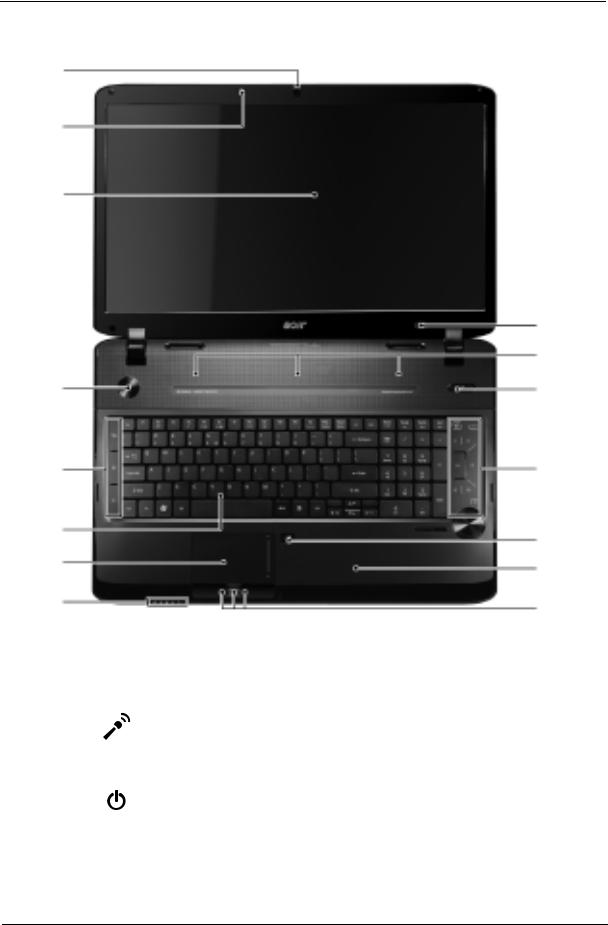
Front View
1
2
3
|
|
|
15 |
|
|
|
14 |
4 |
|
|
13 |
5 |
|
|
12 |
6 |
|
|
11 |
|
|
|
|
7 |
|
|
10 |
8 |
|
|
9 |
|
|
|
|
|
|
|
|
|
Icon |
Item |
Description |
|
|
|
|
1 |
|
Webcam |
Web camera for video communication. |
|
|
|
|
2 |
|
Microphone |
Internal microphone for sound recording. |
|
|
|
|
3 |
|
Display screen |
Also called Liquid-Crystal Display (LCD), displays |
|
|
|
computer output (Configuration may vary by models). |
|
|
|
|
4 |
|
Power button |
Turns the computer on and off. |
|
|
|
|
Chapter 1 |
5 |
|
Icon |
Item |
Description |
||||
|
|
|
|
|
|
|
|
5 |
|
|
|
|
|
Backup key |
Launches backup management software. |
|
|
|
|
|
|
|
|
|
|
|
|
|
|
Bluetooth |
Enables/disables the Bluetooth function. Indicates the |
|
|
|
|
|
|
communication |
status of Bluetooth communication (only for certain |
|
|
|
|
|
|
button/indicator |
models) |
|
|
|
|
|
|
|
|
|
|
|
|
|
|
Wireless LAN |
Enables/disables the wireless LAN function. Indicates |
|
|
|
|
|
|
communication |
the status of wireless LAN communication. |
|
|
|
|
|
|
button/indicator |
|
|
|
|
|
|
|
|
|
6 |
|
|
|
|
|
Keyboard |
For entering data into your computer. |
|
|
|
|
|
|
|
|
7 |
|
|
|
|
|
Touchpad |
Touch-sensitive pointing device which functions like a |
|
|
|
|
|
|
|
computer mouse. |
|
|
|
|
|
|
|
|
8 |
|
|
|
|
|
HDD |
Indicates when the hard disk drive is active. |
|
|
|
|
|
|
|
|
|
|
|
|
|
|
Num Lock |
Lights up when Num Lock is activated. |
|
|
|
|
|
|
|
|
|
|
|
|
|
|
|
|
|
|
|
|
|
|
Caps Lock |
Lights up when Caps Lock is activated. |
|
|
|
|
|
|
|
|
|
|
|
|
|
|
Power |
Indicates the computer's power status. |
|
|
|
|
|
|
|
|
|
|
|
|
|
|
Battery |
Indicates the computer's battery status. |
|
|
|
|
|
|
||
|
|
|
|
|
|
|
• Charging: The light shows amber when the |
|
|
|
|
|
|
|
|
|
|
|
|
|
|
|
battery is charging. |
|
|
|
|
|
|
|
• Fully charged: The light shows blue when in |
|
|
|
|
|
|
|
AC mode. |
|
|
|
|
|
|
|
|
9 |
|
|
|
|
|
Click buttons (left, |
The left and right buttons function like the left and right |
|
|
|
|
|
|
center and right)* |
mouse buttons. |
|
|
|
|
|
|
|
*The center button serves as Acer Bio-Protection |
|
|
|
|
|
|
|
fingerprint reader supporting Acer FingerNav 4-way |
|
|
|
|
|
|
|
control function (only for certain models). |
|
|
|
|
|
|
|
|
10 |
|
|
|
|
|
Palmrest |
Comfortable support area for your hands when you |
|
|
|
|
|
|
|
use the computer. |
|
|
|
|
|
|
|
|
11 |
|
|
|
|
|
Touchpad toggle |
Turns the internal touchpad on and off. |
|
|
|
|
|
|
|
|
12 |
|
|
|
|
|
Acer MediaTouch |
Touch sensitive controls for Acer Arcade, volume (up/ |
|
|
|
|
|
|
|
down) and media (play/pause, stop, previous, next); |
|
|
|
|
|
|
|
with mute and hold keys. |
|
|
|
|
|
|
|
|
13 |
|
|
|
|
|
Acer PowerSmart key |
Puts your computer into power-saving mode. |
|
|
|
|
|
|
|
|
14 |
|
|
|
|
|
Speakers |
Left and right speakers deliver stereo audio output. |
|
|
|
|
|
|
|
|
15 |
|
|
|
|
|
Screen blank |
Turns the display screen backlight off to save power. |
|
|
|
|
|
|
|
Press any key to return. |
|
|
|
|
|
|
|
|
6 |
Chapter 1 |
Closed Front View
3
|
|
|
|
|
|
|
|
|
|
|
|
|
|
|
|
|
|
|
|
|
|
|
|
|
|
|
|
|
|
|
|
|
|
|
|
|
|
|
|
|
|
|
|
|
|
|
|
|
|
|
|
|
|
|
|
|
|
|
|
|
|
|
|
|
|
|
|
|
|
|
|
|
|
|
|
|
|
|
|
|
|
|
|
|
|
1 |
2 |
|
|
|
|
|
|
||
|
|
|
|
|
|
|
|
|
|
|
|||||
|
|
|
|
|
|
|
|
|
|
|
|
||||
|
|
|
|
|
|
|
|
|
|
|
|
|
|
|
|
|
|
|
|
|
|
|
|
|
|
|
|
|
|
|
|
# |
|
|
|
|
Icon |
|
|
Item |
Description |
||||||
|
|
|
|
|
|
|
|
|
|
|
|
|
|
|
|
1 |
|
|
|
|
|
|
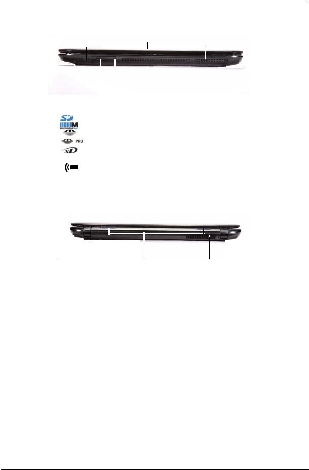
Multi-in-1 card |
Accepts Secure Digital (SD), MultiMediaCard |
|||||||
|
|
|
|
|
|
|
reader |
(MMC), Memory Stick (MS), Memory Stick |
|||||||
|
|
|
|
|
|
|
|
|
|
PRO (MS PRO), xD-Picture Card (xD). |
|||||
|
|
|
|
|
|
|
|
|
|
Note: Push to remove/install the card. Only |
|||||
|
|
|
|
|
|
|
|
|
|
one card can operate at any given time. |
|||||
|
|
|
|
|
|
|
|
|
|
|
|
|
|
|
|
2 |
|
|
|
|
|
|
CIR receiver |
Receives signals from a remote control. |
|||||||
|
|
|
|
|
|
|
|
|
|
|
|
|
|
|
|
3 |
|
|
|
|
|
|
Speakers |
Dolby 5.1 speakers deliver stereo audio output. |
|||||||
|
|
|
|
|
|
|
|
|
|
|
|
|
|
|
|
Rear View
1 |
2 |
|
Item |
Description |
|
|
|
1 |
Tuba |
The dedicated Tuba CineBass subwoofer pumps out |
|
|
earthshaking movie-house audio. |
|
|
|
2 |
Ventilation slots |
Enable the computer to stay cool, even after prolonged use. |
|
|
|
Chapter 1 |
7 |
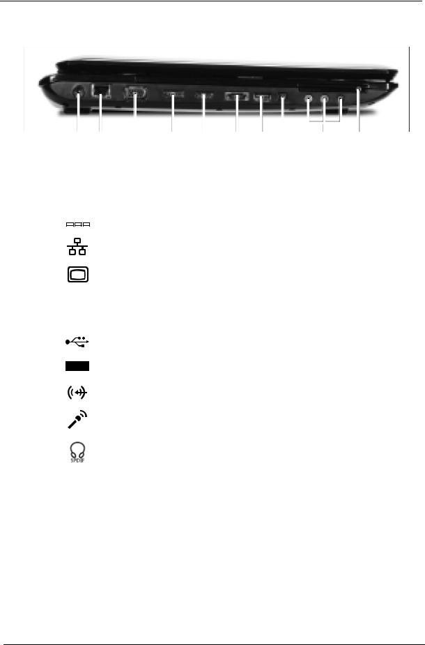
Left View
1 |
|
|
|
|
|
|
|
|
|
|
|
|
|
|
|
|
|
|
|
|
|
|
|
|
|
|
|
|
|
|
|
|
|
|
|
|
|
|
|
|
|
|
|
|
|
|
|
|
|
|
|
|
|
|
|
|
|
2 |
3 |
4 |
5 |
|
6 |
|
7 |
8 |
9 |
10 |
|||||||
# |
|
Icon |
Item |
Description |
|||||
|
|
|
|
|
|
|
|
|
|
1 |
|
|
|
|
|
|
|
DC-in jack |
Connects to an AC adapter. |
|
|
|
|
|
|
|
|||
|
|
|
|
|
|
|
|||
|
|
|
|
|
|
|
|
|
|
|
|
|
|
|
|
|
|
|
|
2 |
|
|
|
|
|
|
|
Ethernet (RJ-45) |
Connects to an Ethernet 10/100/1000-based network. |
|
|
|
|
|
|
|
|
port |
|
|
|
|
|
|
|
|
|
|
|
3 |
|
|
|
|
|
|
|
External display |
Connects to a display device (e.g., external monitor, |
|
|
|
|
|
|
|
|
(VGA) port |
LCD projector). |
|
|
|
|
|
|
|
|
|
|
4 |
DISPLAY |
DISPLAY port |
Supports high definition digital video connections. |
||||||
|
|
|
|
|
|
|
|
|
|
5 |
|
HDMI |
HDMI port |
Supports high definition digital video connections. |
|||||
|
|
|
|
|
|
|
|
|
|
6 |
eSATA |
e SATA port |
Connects to eSATA devices (only for certain models). |
||||||
|
|
|
|
|
|
|
|
|
|
7 |
|
|
|
|
|
|
|
USB 2.0 port |
Connects to USB 2.0 devices (e.g., USB mouse, USB |
|
|
|
|
|
|
|
|
|
camera). |
|
|
|
|
|
|
|
|
|
|
8 |
|
|
|
|
|
|
|
4-pin IEEE 1394 |
Connects to IEEE 1394 devices. |
|
|
|
|
|
|
|
|
port |
|
|
|
|
|
|
|
|
|
|
|
9 |
|
|
|
|
|
|
|
Line-in jack |
Accepts audio line-in devices (e.g., audio CD player, |
|
|
|
|
|
|
|
|
|
stereo walkman, mp3 player) |
|
|
|
|
|
|
|
|
|
|
|
|
|
|
|
|
|
|
Microphone-in jack |
Accepts inputs from external microphones. |
|
|
|
|
|
|
|
|
|
|
|
|
|
|
|
|
|
|
Headphones/ |
Connects to audio line-out devices (e.g., speakers, |
|
|
|
|
|
|
|
|
speaker/line-out |
headphones). |
|
|
|
|
|
|
|
|
jack with S/PDIF |
|
|
|
|
|
|
|
|
|
support |
|
10 |
Expresscard / 54 |
ExpressCard/54 |
Accepts one ExpressCard/54 module. |
||||||
|
|
|
|
|
|
|
|
slot |
|
|
|
|
|
|
|
|
|
|
|
8 |
Chapter 1 |
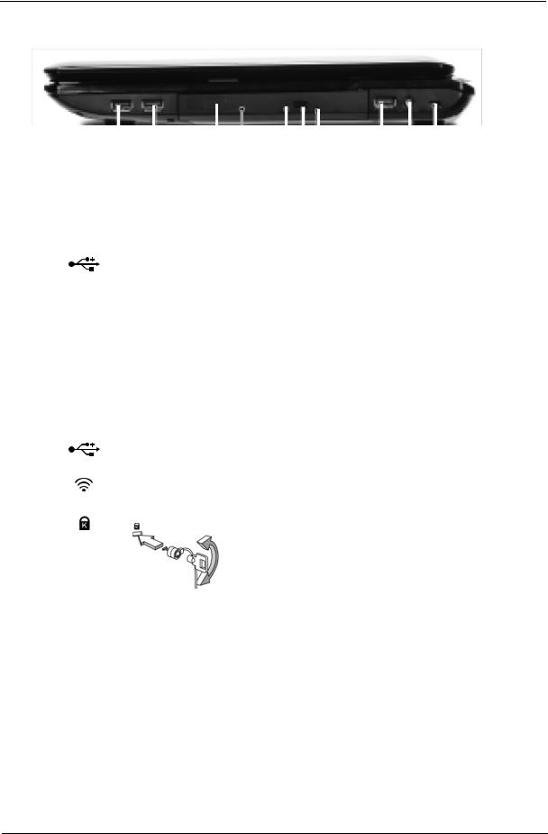
Right View
|
|
|
|
|
|
|
|
|
|
|
|
|
|
|
|
|
|
|
|
|
|
|
|
|
|
|
|
|
|
|
|
|
|
|
|
|
|
|
|
|
|
|
|
|
|
|
|
|
|
|
|
|
|
|
|
|
|
|
|
1 |
|
2 |
3 |
4 |
5 |
6 |
7 |
8 |
|||||||
|
|
|
|
|
|
|
|
|
|
|
|
|
|
|
|
|
|
|
|
Icon |
|
|
Item |
|
|
|
|
|
|
|
Description |
|
|
||||
|
|
|
|
|
|
|
|
|
|
|
|
|
|
|
||||
1 |
|
|
USB 2.0 port |
|
|
Connects to USB 2.0 devices (e.g., USB mouse, |
||||||||||||
|
|
|
|
|
|
|
|
USB camera). |
|
|
|
|
|
|
||||
|
|
|
|
|
|
|
|
|
|
|
|
|
|
|
||||
2 |
|
|
Optical drive |
|
|
Internal optical drive; accepts CDs or DVDs. |
||||||||||||
|
|
|
|
|
|
|
|
|
|
|
|
|
|
|||||
3 |
|
|
Optical disk access |
Lights up when the optical drive is active. |
||||||||||||||
|
|
|
indicator |
|
|
|
|
|
|
|
|
|
|
|
|
|
||
|
|
|
|
|
|
|
|
|
|
|
|
|
|
|
||||
4 |
|
|
Optical drive eject |
Ejects the optical disk from the drive. |
|
|
||||||||||||
|
|
|
button |
|
|
|
|
|
|
|
|
|
|
|
|
|
||
|
|
|
|
|
|
|
|
|
|
|
|
|
|
|||||
5 |
|
|
Emergency eject hole |
Ejects the optical drive tray when the computer is |
||||||||||||||
|
|
|
|
|
|
|
|
turned off. |
|
|
|
|
|
|
|
|
||
|
|
|
|
|
|
|
|
Note: Insert a paper clip to the emergency eject hole |
||||||||||
|
|
|
|
|
|
|
|
to eject the optical drive tray when the computer is |
||||||||||
|
|
|
|
|
|
|
|
off. |
|
|
|
|
|
|
|
|
|
|
|
|
|
|
|
|
|
|
|
|
|
|
|
|
|
||||
6 |
|
|
USB 2.0 port |
|
|
Connects to USB 2.0 devices (e.g., USB mouse, |
||||||||||||
|
|
|
|
|
|
|
|
USB camera). |
|
|
|
|
|
|
||||
|
|
|
|
|
|
|
|
|
|
|
|
|
|
|
||||
7 |
|
|
RF-in port |
|
|
Accepts input signals from digital TV tuner devices. |
||||||||||||
|
|
|
|
|
|
|
|
(only for certain models) |
|
|
|
|
||||||
|
|
|
|
|
|
|
|
|
|
|
|
|
|
|||||
8 |
|
|
Kensington lock slot |
Connects to a Kensington-compatible computer |
||||||||||||||
|
|
|
|
|
|
|
|
security lock. |
|
|
|
|
|
|
||||
|
|
|
|
|
|
|
|
Note: Wrap the computer security lock cable around |
||||||||||
|
|
|
|
|
|
|
|
an immovable object such as a table or handle of a |
||||||||||
|
|
|
|
|
|
|
|
locked drawer. Insert the lock into the notch and turn |
||||||||||
|
|
|
|
|
|
|
|
the key to secure the lock. Some keyless models are |
||||||||||
|
|
|
|
|
|
|
|
also available. |
|
|
|
|
|
|
||||
|
|
|
|
|
|
|
|
|
|
|
|
|
|
|
|
|
|
|
Chapter 1 |
9 |
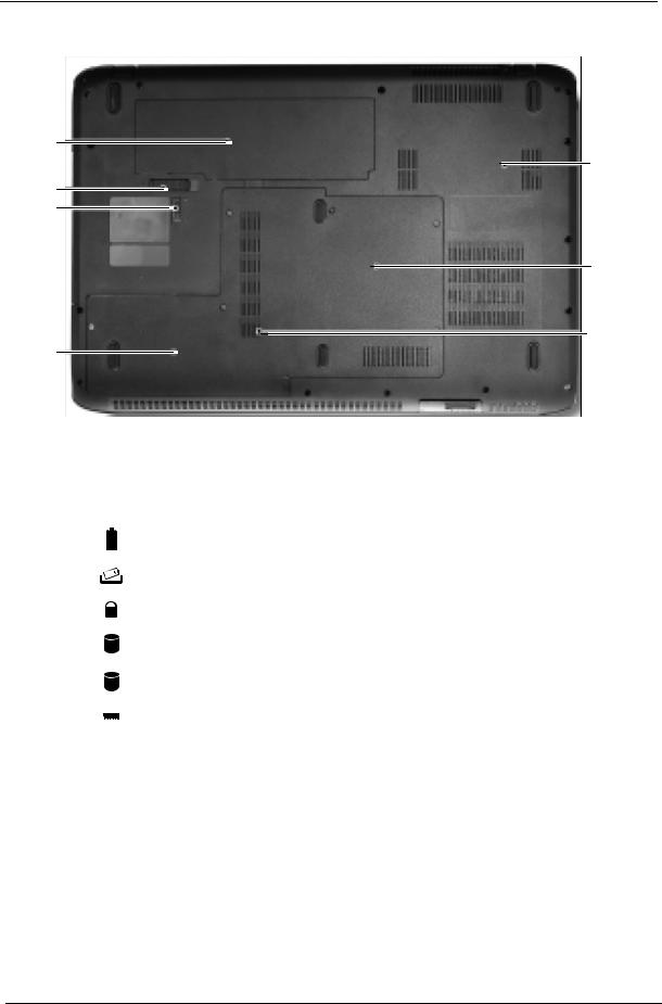
Bottom View
1
7
2
3
6
5
4
|
Icon |
Item |
Description |
||
|
|
|
|
|
|
1 |
|
|
|
Battery bay |
Houses the computer's battery pack. |
|
|
|
|||
|
|
|
|
|
|
|
|
|
|
|
|
2 |
|
|
|
Battery release latch |
Releases the battery for removal. |
|
|
|
|
|
|
3 |
|
|
|
Battery lock |
Locks the battery in position. |
|
|
|
|
|
|
4 |
|
|
|
Hard drive bay- |
Houses the computer’s hard disk (secured with screws) |
|
|
|
|
Secondary |
(for certain models only). |
5 |
|
|
|
Hard disk bay-Main |
Houses the computer's hard disk (secured |
|
|
|
|
|
with screws). |
|
|
|
|
|
|
6 |
|
|
|
Memory compartment |
Houses the computer’s main memory |
|
|
|
|
|
|
7 |
|
|
|
Ventilation slots and |
Enable the computer to stay cool, even after prolonged |
|
|
|
|
cooling fan |
use. |
|
|
|
|
|
Note: Do not cover or obstruct the opening of the fan. |
|
|
|
|
|
|
10 |
Chapter 1 |
TouchPad Basics
The following items show you how to use the TouchPad:
•Move your finger across the touchpad (1) to move the cursor.
•Press the left (2) and right (4) buttons located beneath the touchpad to perform selection and execution functions. These two buttons are similar to the left and right buttons on a mouse. Tapping on the touchpad is the same as clicking the left button.
•Use Acer Bio-Protection fingerprint reader (3) supporting Acer FingerNav 4-way control function (only for certain models) or the 4-way scroll (3) button (only for certain models) to scroll up or down and move left or right a page. This fingerprint reader or button mimics your cursor pressing on the right scroll bar of Windows applications.
Function |
Left Button (2) |
Right Button (4) |
Main TouchPad (1) |
|
|
|
|
Execute |
Quickly click twice. |
|
Tap twice (at the same speed |
|
|
|
as double-clicking a mouse |
|
|
|
button). |
|
|
|
|
Select |
Click once. |
|
Tap once. |
|
|
|
|
Drag |
Click and hold, then use |
|
Tap twice (at the same speed |
|
finger on the TouchPad to |
|
as double-clicking a mouse |
|
drag the cursor. |
|
button); rest your finger on |
|
|
|
the TouchPad on the second |
|
|
|
tap and drag the cursor. |
|
|
|
|
Access |
|
Click once. |
|
context menu |
|
|
|
|
|
|
|
NOTE: When using the TouchPad, keep it - and your fingers - dry and clean. The TouchPad is sensitive to finger movement; hence, the lighter the touch, the better the response. Tapping too hard will not increase the TouchPad’s responsiveness.
Chapter 1 |
11 |

Using the Keyboard
Your notebook features a full-size keyboard that functions the same as a desktop computer keyboard. Many of the keys have been assigned alternate functions, including shortcut keys for Windows, function keys for specific system operations, and the Num Lock keys for the numeric keypad.
Key Types
The keyboard has several different types of keys. Some keys perform specific actions when pressed alone and other actions when pressed in combination with another key.
Icon |
Key Type |
Description |
|
|
|
|
Function keys |
Press these keys labeled F1 to F12 to perform actions in |
|
|
programs. For example, pressing F1 may open help. Each |
|
|
program uses different function keys for different purposes. |
|
|
See the program documentation to find out more about the |
|
|
function key actions. |
|
|
|
|
System keys |
Press these colored keys in combination with the Fn key to |
|
|
perform specific actions. See “System Hotkeys” on page 14. |
|
|
|
|
Navigation keys |
Press these keys to move the cursor to the beginning of a line, |
|
|
to the end of a line, up the page, down the page, to the |
|
|
beginning of a document, or to the end of a document. |
|
|
|
|
Fn key |
Press the Fn key in combination with a colored system key to |
|
|
perform a specific action. |
|
|
|
|
Windows key |
Press this key to open the Windows Start menu. This key |
|
|
can also be used in combination with other keys to open |
|
|
utilities. See “Windows Keys” on page 13. |
|
|
|
|
Application key |
Press this key for quick access to shortcut menus and help |
|
|
assistants in Windows. |
|
|
|
|
Arrow keys |
Press these keys to move the cursor up, down, right, or left. |
|
|
|
12 |
Chapter 1 |
Windows Keys
The keyboard has two keys that perform Windows-specific functions.
Key |
Description |
|
|
Windows key |
Pressed alone, this key has the same effect as clicking on the Windows Start button; |
|
it launches the Start menu. It can also be used with other keys to provide a variety of |
|
functions: |
|
< >: Open or close the Start menu |
|
< > + <D>: Display the desktop |
|
< > + <E>: Open Windows Explore |
|
< > + <F>: Search for a file or folder |
|
< > + <G>: Cycle through Sidebar gadgets |
|
< > + <L>: Lock your computer (if you are connected to a network domain), or |
|
switch users (if you're not connected to a network domain) |
|
< > + <M>: Minimizes all windows |
|
< > + <R>: Open the Run dialog box |
|
< > + <T>: Cycle through programs on the taskbar |
|
< > + <U>: Open Ease of Access Center |
|
< > + <X>: Open Windows Mobility Center |
|
< > + <BREAK>: Display the System Properties dialog box |
|
< > + <SHIFT+M>: Restore minimized windows to the desktop |
|
< > + <TAB>: Cycle through programs on the taskbar by using Windows Flip 3-D |
|
< > + <SPACEBAR>: Bring all gadgets to the front and select Windows Sidebar |
|
<CTRL> + < > + <F>: Search for computers (if you are on a network) |
|
<CTRL> + < > + <TAB>: Use the arrow keys to cycle through programs on the |
|
taskbar by using Windows Flip 3-D |
|
Note: Depending on your edition of Windows 7, some shortcuts may not function as |
|
described. |
Chapter 1 |
13 |
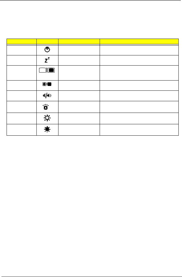
System Hotkeys
The computer employs hotkeys or key combinations to access most of the computer’s controls like screen brightness, Bluetooth and WiFi.
To activate hot keys, press and hold the <Fn> key before pressing the other key in the hotkey combination.
Hotkey |
Icon |
Function |
Remarks |
Fn + F2 |
|
System property |
Starts System Property for displaying system |
|
|
|
information. |
Fn + F4 |
|
Sleep |
Puts the computer in Sleep mode. |
<Fn> + <F5> |
|
Display toggle |
Switches display output between the display |
|
|
|
screen, external monitor (if connected) and |
|
|
|
both. |
<Fn> + <F6> |
|
Screen blank |
Turns the display screen backlight off to save |
|
|
|
power. Press any key to return. |
<Fn> + <F8> |
|
Speaker toggle |
Turns the speakers on and off. |
<Fn> + <F9> |
|
Keyboard backlight |
Turns the keyboard backlight on or off. |
|
|
toggle |
|
<Fn> + < > |
|
Brightness up |
Increases the screen brightness. |
<Fn> + < > |
|
Brightness down |
Decreases the screen brightness. |
14 |
Chapter 1 |

Hardware Specifications and Configurations
Processor
|
Item |
|
|
|
|
|
|
Specification |
|
|
|
|||
|
|
|
|
|
|
|
|
|
|
|
|
|
|
|
|
CPU |
|
|
Intel® Core™ i7 processor |
|
|
|
|
|
|
|
|||
|
|
|
|
|
|
|
|
|
|
|
|
|
|
|
|
Type |
|
|
1.6GHz ~ 1.73GHz CPU |
|
|
|
|
|
|
|
|||
|
|
|
|
|
|
|
|
|
|
|
|
|
||
|
Core Logic |
|
|
• Mobile Intel® HM55 Express Chipset |
|
|
|
|||||||
|
|
|
|
|
• REALTEK ALC669X for High Definition Audio Codec |
|
|
|||||||
|
|
|
|
|
|
|
|
|
|
|
|
|||
|
CPU Package |
|
37.5 x 37.5 mm rPGA package (rPGA988A) |
|
|
|
||||||||
|
|
|
|
|
|
|
|
|
|
|
|
|
|
|
|
Power |
|
|
Vcca 1.5V, Vccp 1.05V |
|
|
|
|
|
|
|
|||
|
|
|
|
|
|
|
|
|
|
|
|
|
|
|
|
On-die Cache |
|
8MB or 256KMB L2 cache |
|
|
|
|
|
|
|
||||
|
|
|
|
|
|
|
|
|
|
|
|
|
|
|
|
Front Side Bus |
|
667/800/1066 MHz |
|
|
|
|
|
|
|
||||
|
|
|
|
|
|
|
|
|
|
|
|
|
|
|
|
Thermal IC |
|
|
Digital thermal sensor (DTS) |
|
|
|
|
|
|
||||
|
|
|
|
|
|
|
|
|
|
|
|
|
|
|
|
Processor Specifications |
|
|
|
|
|
|
|
|
|
|
|||
|
|
|
|
|
|
|
|
|
|
|
|
|
|
|
|
Item |
|
CPU |
|
Cores |
Bus Speed |
|
Cache |
Package |
|
Power |
PN |
|
|
|
|
Speed |
|
|
Size |
|
|
|
||||||
|
|
|
|
|
|
|
|
|
|
|
|
|
||
|
|
|
|
|
|
|
|
|
|
|
|
|
|
|
|
i7 720QM |
|
1.6 GHz |
|
4 |
1066 MT/s |
|
8 MB |
|
37.5 x 37.5 |
|
45 W |
KC.72001.QMP |
|
|
|
|
|
|
|
and 1333 |
|
|
|
mm rPGA |
|
|
|
|
|
|
|
|
|
|
MT/s |
|
|
|
package |
|
|
|
|
|
|
|
|
|
|
|
|
|
|
(988 pin) |
|
|
|
|
|
|
|
|
|
|
|
|
|
|
|
|
|
|
|
|
i7 720QM |
|
1.73 GHz |
|
4 |
1066 MT/s |
|
8 MB |
|
37.5 x 37.5 |
|
45 W |
KC.82001.QMP |
|
|
|
|
|
|
|
and 1333 |
|
|
|
mm rPGA |
|
|
|
|
|
|
|
|
|
|
MT/s |
|
|
|
package |
|
|
|
|
|
|
|
|
|
|
|
|
|
|
(988 pin) |
|
|
|
|
|
|
|
|
|
|
|
|
|
|
|
|
|
|
|
|
i3 330M |
|
2.13GHz |
|
2 |
1066 MT/s |
|
3 MB |
|
PGA |
|
35 W |
N/A |
|
|
|
|
|
|
|
and 1333 |
|
|
|
|
|
|
|
|
|
|
|
|
|
|
MT/s |
|
|
|
|
|
|
|
|
|
|
|
|
|
|
|
|
|
|
|
|
|
|
|
|
i3 350M |
|
2.26GHz |
|
2 |
1066 MT/s |
|
3 MB |
|
PGA |
|
35 W |
N/A |
|
|
|
|
|
|
|
and 1333 |
|
|
|
|
|
|
|
|
|
|
|
|
|
|
MT/s |
|
|
|
|
|
|
|
|
|
|
|
|
|
|
|
|
|
|
|
|
|
|
|
|
i5 430M |
|
2.26GHz |
|
2 |
1066 MT/s |
|
3 MB |
|
PGA |
|
N/A |
N/A |
|
|
|
|
|
|
|
and 1333 |
|
|
|
|
|
|
|
|
|
|
|
|
|
|
MT/s |
|
|
|
|
|
|
|
|
|
|
|
|
|
|
|
|
|
|
|
|
|
|
|
|
i5 520M |
|
2.4GHz |
|
2 |
1066 MT/s |
|
3 MB |
|
PGA |
|
N/A |
N/A |
|
|
|
|
|
|
|
and 1333 |
|
|
|
|
|
|
|
|
|
|
|
|
|
|
MT/s |
|
|
|
|
|
|
|
|
|
|
|
|
|
|
|
|
|
|
|
|
|
|
|
|
i5 540M |
|
2.54GHz |
|
2 |
1066 MT/s |
|
3 MB |
|
PGA |
|
N/A |
N/A |
|
|
|
|
|
|
|
and 1333 |
|
|
|
|
|
|
|
|
|
|
|
|
|
|
MT/s |
|
|
|
|
|
|
|
|
|
|
|
|
|
|
|
|
|
|
|
|
|
|
|
|
i7 620M |
|
2.66GHz |
|
4 |
1066 MT/s |
|
4MB |
|
PGA |
|
N/A |
N/A |
|
|
|
|
|
|
|
and 1333 |
|
|
|
|
|
|
|
|
|
|
|
|
|
|
MT/s |
|
|
|
|
|
|
|
|
|
|
|
|
|
|
|
|
|
|
|
|
|
||
|
CPU/VGA Fan True Value Table |
|
|
|
|
|
|
|
|
|
||||
|
|
|
|
|
|
|
|
|
|
|
|
|
||
|
Fan On Temp (°C) |
|
Fan Speed (rpm) |
|
SPL Spec (dBA) |
|
|
|
||||||
|
|
|
|
|
|
|
|
|
|
|
|
|
|
|
|
45 |
|
|
|
2350 |
|
|
31 |
|
|
|
|
|
|
|
55 |
|
|
|
2660 |
|
|
34 |
|
|
|
|
|
|
|
|
|
|
|
|
|
|
|
|
|
|
|
|
|
|
65 |
|
|
|
2950 |
|
|
38 |
|
|
|
|
|
|
|
|
|
|
|
|
|
|
|
|
|
|
|
|
|
|
75 |
|
|
|
3250 |
|
|
40 |
|
|
|
|
|
|
|
|
|
|
|
|
|
|
|
|
|
|
|
|
|
|
95 |
|
|
|
3500 |
|
|
|
|
|
|
|
|
|
|
|
|
|
|
|
|
|
|
|
|
|
|
|
|
Chapter 1 |
15 |

•Throttling 50%: On=100°C, Off=90°C
•OS Shutdown: 110°C
•H/W Shutdown: 110°C
Northbridge
Item |
|
|
|
|
Specification |
||
|
|
|
|
|
|
||
Chipset |
|
NB Chipset Intel CS GM45NB B3 |
|||||
Package |
|
FCBGA 27 mm x 25 mm - 1071 pins |
|||||
|
|
|
|
|
|
|
|
VGA Subsystem |
|
|
|
|
|
|
|
|
|
|
|
|
|
|
|
Item |
|
|
|
Specification |
|
||
|
|
|
|
|
|
|
|
Chipset |
|
Broadway-Pro or Madison-Pro |
|
|
|
||
|
|
|
|
|
|
|
|
Vendor |
|
AMD |
|
|
|
||
|
|
|
|
|
|
||
Package |
|
962-pins FCBGA 29mm x 29mm |
|
||||
|
|
|
|
|
|
||
Features |
|
• Fully DirectX® 11 compliant, including full speed 32-bit |
|
||||
|
|
|
floating point per component operation. |
|
|||
|
|
• Support for OpenGL® 3.1. |
|
||||
|
|
• Support for OpenCLTM 1.1. |
|
||||
|
|
• Anti-Aliasing Filtering. |
|
|
|
||
|
|
• |
Anisotropic Filtering: |
|
|
|
|
|
|
• Hardware support to overcome "Small batch" issues |
|
||||
|
|
|
in CPU limited applications. |
|
|||
|
|
• 3D resources virtualized to a 36-b addressing space, |
|
||||
|
|
|
for support of large numbers of render targets and |
|
|||
|
|
|
textures. |
|
|
|
|
|
|
• Up to 16-k x 16-k textures, including 128-bit/pixel |
|
||||
|
|
|
texture are supported. |
|
|
|
|
|
|
• Programmable arbitration logic maximizes memory |
|
||||
|
|
|
efficiency, software upgradeable. |
|
|||
|
|
• Fully associative texture, color, and z-cache design. |
|
||||
|
|
• Hierarchical z- and stencil-buffers with early z test. |
|
||||
|
|
• Lossless z-buffer compression for both z and stencil. |
|
||||
|
|
• Fast z-buffer clear. |
|
|
|
||
|
|
• Fast color buffer clear. |
|
|
|
||
|
|
• Z cache optimized for real-time shadow rendering. |
|
||||
|
|
• Z and color compression resources virtualized to a |
|
||||
|
|
|
32-bit addressing space, for support of multiple render |
|
|||
|
|
|
targets and textures simultaneously. |
|
|||
Standard Supported VGA Resolution |
|
|
|
||||
|
|
|
|
|
|
|
|
Resolution |
Color Depth |
|
Refresh Rate |
|
|
||
|
|
|
|
|
|
||
640 x 480 |
8, 16 |
|
60 70 72 75 85 100 120 |
|
|
||
|
|
|
|
|
|
||
800 x 600 |
8, 16 |
|
60 70 72 75 85 100 120 |
|
|
||
|
|
|
|
|
|
||
1024 x 768 |
8, 16 |
|
60 70 72 75 85 100 120 |
|
|
||
|
|
|
|
|
|
||
1152 x 864 |
8, 16 |
|
60 70 72 75 85 100 120 |
|
|
||
|
|
|
|
|
|
|
|
1280 x 720 |
8, 16 |
|
60 |
|
|
|
|
|
|
|
|
|
|
||
1280 x 768 |
8, 16 |
|
60 70 72 75 85 100 120 140 144 150 |
|
|
||
|
|
|
|
|
|
|
|
16 |
Chapter 1 |

Resolution |
Color Depth |
Refresh Rate |
|
|
|
1280 x 800 |
8, 16 |
60 70 72 75 85 100 120 140 144 150 |
1280 x 960 |
8, 16 |
60 70 72 75 85 100 120 |
|
|
|
1280 x 1024 |
8, 16 |
60 70 72 75 85 100 120 |
|
|
|
1360 x 768 |
8, 16 |
60 70 72 75 85 100 120 140 144 150 |
|
|
|
1400 x 1050 |
8, 16 |
60 70 72 75 85 100 |
|
|
|
1600 x 1024 |
8, 16 |
60 70 72 75 85 100 |
|
|
|
1600 x 1200 |
8, 16 |
60 70 72 75 85 100 |
|
|
|
1920 x 1200 |
8, 16 |
60 70 72 75 85 |
|
|
|
1920 x 1440 |
8, 16 |
60 70 72 75 85 |
|
|
|
2048 x 1536 |
8, 16 |
60 70 72 75 85 |
|
|
|
640 x 480 |
32,64 |
60 70 72 75 85 100 120 |
|
|
|
800 x 600 |
32,64 |
60 70 72 75 85 100 120 |
|
|
|
1024 x 768 |
32,64 |
60 70 72 75 85 100 120 140 144 150 170 200 |
|
|
|
1152 x 864 |
32,64 |
60 70 72 75 85 100 120 140 144 150 170 |
|
|
|
1280 x 720 |
32,64 |
60 |
|
|
|
1280 x 768 |
32,64 |
60 70 72 75 85 100 120 140 144 150 |
|
|
|
1280 x 800 |
32,64 |
60 70 72 75 85 100 120 140 144 150 |
|
|
|
1280 x 960 |
32,64 |
60 70 72 75 85 100 120 140 144 150 |
|
|
|
1280 x 1024 |
32,64 |
60 70 72 75 85 100 120 140 144 150 |
|
|
|
1360 x 768 |
32,64 |
60 70 72 75 85 100 120 140 144 150 |
|
|
|
1400 x 1050 |
32,64 |
60 70 72 75 85 |
|
|
|
1600 x 1024 |
32,64 |
60 70 72 75 85 |
|
|
|
1600 x 1200 |
32,64 |
60 70 72 75 85 100 |
|
|
|
1920 x 1200 |
32,64 |
60 70 72 75 85 |
|
|
|
1920 x 1440 |
32,64 |
60 70 72 75 85 |
|
|
|
2048 x 1536 |
32,64 |
60 70 72 75 85 |
|
|
|
BIOS
Item |
Specification |
|
|
BIOS vendor |
Phoenix |
BIOS Version |
V0.07 |
|
|
BIOS ROM type |
Flash ROM W25x16 |
|
|
Package |
8-pin SOIC |
|
|
Chapter 1 |
17 |

Item |
|
Specification |
|
|
|
Features |
• |
Flash ROM 1MB |
|
• |
Support ISIPP |
|
• |
Support Acer UI |
|
• Support multi-boot |
|
|
• Suspend to RAM (S3)/Disk (S4) |
|
|
• Various hot-keys for system control |
|
|
• Support SMBUS 2.0, PCI2.3 |
|
|
• ACPI 2.0 compliance with Intel Speed Step Support C1, C2, |
|
|
|
C3, C4,C6 and S3, S4 for mobile CPU |
|
• DMI utility for BIOS serial number configurable/asset tag |
|
|
• |
Support PXE |
|
• |
Support Y2K solution |
|
• Support Win Flash Wake on LAN from S3 |
|
|
• Wake on LAN form S4 in AC mode |
|
|
• |
System information |
|
|
|
System Memory |
|
|
|
|
|
Item |
|
Specification |
|
|
|
Memory controller |
Intel® Core™ i7 processor with Mobile Intel® HM55 Express |
|
|
Chipset |
|
|
|
|
Memory size |
4GB |
|
|
|
|
DIMM socket number |
2 |
|
|
|
|
Supports memory size per socket |
2GB |
|
|
|
|
Supports maximum memory size |
Up to 8GB using two soDIMM modules |
|
|
|
|
Supports DIMM type |
DDRIII |
|
|
|
|
Supports DIMM Speed |
667/800/1066 MHz |
|
|
|
|
Supports DIMM voltage |
1.5V |
|
|
|
|
Cache |
8MB |
|
|
|
|
18 |
Chapter 1 |

Memory Combinations
Slot 1 |
Slot 2 |
Total Memory |
|
|
|
0MB |
512MB |
512MB |
0MB |
1024MB |
1024MB |
|
|
|
0MB |
2048MB |
2048MB |
|
|
|
512MB |
512MB |
1024MB |
|
|
|
512MB |
1024MB |
1536MB |
|
|
|
512MB |
2048MB |
2560MB |
|
|
|
1024MB |
0MB |
1024MB |
|
|
|
1024MB |
512MB |
1536MB |
|
|
|
1024MB |
1024MB |
2048MB |
|
|
|
1024MB |
2048MB |
3072MB |
|
|
|
1024MB |
4096MB |
5120MB |
|
|
|
2048MB |
0MB |
2048MB |
|
|
|
2048MB |
512MB |
2560MB |
|
|
|
2048MB |
1024MB |
3072MB |
|
|
|
2048MB |
2048MB |
4096MB |
|
|
|
2048MB |
4096MB |
6144MB |
|
|
|
4096MB |
4096MB |
8192MB |
|
|
|
NOTE: Above table lists some system memory configurations. You may combine DIMMs with various capacities to form other combinations. On above table, the configuration of slot 1 and slot 2 could be reversed.
VGA controller
Item |
|
Specification |
|
|
|
VGA Chipset |
ATI Mobility Radeon HD 5850 GPU |
|
|
|
|
Package |
962 FCBGA |
|
|
|
|
Features |
• 2.15 billion 40nm transistorsI |
|
|
• TeraScale 2 Unified Processing Architecture |
|
|
• GDDR5 interface with 128.0 GB/sec of memory bandwidth |
|
|
• PCI Express 2.1 x16 bus interface |
|
|
• |
DirectX® 11 support |
|
• |
OpenGL 3.2 support |
|
• Image quality enhancement technology |
|
|
• ATI Eyefinity multi-display technology |
|
|
• ATI Stream acceleration technology |
|
|
• ATI CrossFireX™ multi-GPU technology |
|
|
• ATI Avivo™ HD Video & Display technology |
|
|
• ATI PowerPlay™ power management technology |
|
|
|
|
Interface |
PCIe v1.1 bus |
|
|
|
|
LAN Interface |
|
|
|
|
|
Item |
|
Specification |
|
|
|
LAN Chipset |
Broadcom BCM5784MKM for 10/100/1000LAN |
|
|
|
|
Package |
68-pin QFN |
|
|
|
|
LAN connector type |
RJ11 |
|
|
|
|
Chapter 1 |
19 |

Item |
|
|
Specification |
|
|
|
|
|
|
Features |
• |
Integrated 10/100/1000BASE-T transceiver |
|
|
|
• Automatic MDI crossover function |
|
||
|
• |
PCIe v1.1 compliant |
|
|
|
• |
10/100/1000BASE-T full-duplex/half-duplex MAC |
|
|
|
• Receive side scaling (RSS) for multicore processors |
|
||
|
• Complies with IEEE 802.3, 802.3u, 802.3ab, and 802.1p |
|
||
|
• IPv4 and IPv6 large send offload and checksum offload (LSO/TCO) |
|
||
|
• Wake on LAN (WOL) support meeting the ACPI requirements |
|
||
|
• Statistics for SNMP MIB II, Ethernet-like MIB, and Ethernet MIB |
|
||
|
|
(IEEE 802.3z, Clause 30) |
|
|
|
• Self-boot feature, utilizing smaller EEPROM size |
|
||
|
• Serial flash memory support |
|
||
|
• PCI Express CLKREQ support |
|
||
|
• |
Energy Detect/Cable Sense |
|
|
|
• Super Low Power Mode, for ultra-low power consumption |
|
||
|
• 68-pin QFN package |
|
||
|
|
|
|
|
Interface |
PCIe v1.1 bus |
|
||
|
|
|
|
|
Wireless Module 802.11b/g |
|
|
|
|
|
|
|
|
|
Item |
|
|
Specification |
|
|
|
|
|
|
Manufacturer |
|
|
Intel WiFi Link 5000 series |
|
|
|
|
|
|
Model |
|
|
Intel® WiFi Link 5100 and Intel® WiFi Link 5300 (Intel® |
|
|
|
|
WiFi Link 5300/5100) integrated Wi-Fi |
|
|
|
|
|
|
Frequency Range |
|
|
Automatic switching between the two band 2.4GHz and |
|
|
|
|
5.0GHz |
|
|
|
|
|
|
Interface |
|
|
mini PCI Express card |
|
|
|
|
|
|
Bluetooth |
|
|
|
|
|
|
|
|
|
Item |
|
|
Specification |
|
|
|
|
|
|
Model |
|
|
FoxConn T60H928.33 |
|
|
|
|
|
|
Operating Frequency |
|
|
2.402GHz ~ 2.480GHz |
|
|
|
|
|
|
Channel Numbers |
|
|
79 channels with 1MHz BW |
|
|
|
|
|
|
Transmitter Output Power |
|
|
-6~4dBm output power for BT class 2 operation |
|
|
|
|
|
|
Receiver Sensitivity |
|
|
-75dBm, BER<0.1% |
|
|
|
|
|
|
Maximum Receiver Signal |
|
|
-10dBm |
|
|
|
|
|
|
Operating Voltage |
|
|
3.3V+/-0.3V |
|
|
|
|
|
|
Interface |
|
|
USB |
|
|
|
|
|
|
Modem |
|
|
|
|
|
|
|
|
|
Item |
|
|
Specification |
|
|
|
|
|
|
Model |
|
|
Agere Argos A40 (D-1156U#/A9B) |
|
|
|
|
|
|
Interface |
|
|
Two-chip USB 2.0 |
|
|
|
|
|
|
Package |
|
|
SV92U2 host interface in a 48-pin TQFP |
|
|
|
|
|
|
Power supply |
|
|
USB supply voltage 5.0V±0.5V |
|
|
|
|
|
|
20 |
Chapter 1 |
Loading...