


 Loading...
Aspire 7736/7736Z/7336 Series
Aspire 7540 Series
Service Guide
Service guide files and updates are available on the ACER/CSD web; for more information, please refer to http://csd.acer.com.tw
PRINTED IN TAIWAN

Revision History
Please refer to the table below for the updates made on Aspire 7736/7736Z/7336 and Aspire 7540 Series service guide.
Date |
Chapter |
Updates |
|
|
|
|
|
|
|
|
|
|
|
|
II

Copyright
Copyright © 2009 by Acer Incorporated. All rights reserved. No part of this publication may be reproduced, transmitted, transcribed, stored in a retrieval system, or translated into any language or computer language, in any form or by any means, electronic, mechanical, magnetic, optical, chemical, manual or otherwise, without the prior written permission of Acer Incorporated.
Disclaimer
The information in this guide is subject to change without notice.
Acer Incorporated makes no representations or warranties, either expressed or implied, with respect to the contents hereof and specifically disclaims any warranties of merchantability or fitness for any particular purpose. Any Acer Incorporated software described in this manual is sold or licensed "as is". Should the programs prove defective following their purchase, the buyer (and not Acer Incorporated, its distributor, or its dealer) assumes the entire cost of all necessary servicing, repair, and any incidental or consequential damages resulting from any defect in the software.
Acer is a registered trademark of Acer Corporation. Intel is a registered trademark of Intel Corporation.
Other brand and product names are trademarks and/or registered trademarks of their respective holders.
III

Conventions
The following conventions are used in this manual:
SCREEN MESSAGES |
Denotes actual messages that appear |
|
on screen. |
|
|
NOTE |
Gives bits and pieces of additional |
|
information related to the current |
|
topic. |
|
|
WARNING |
Alerts you to any damage that might |
|
result from doing or not doing specific |
|
actions. |
|
|
CAUTION |
Gives precautionary measures to |
|
avoid possible hardware or software |
|
problems. |
|
|
IMPORTANT |
Reminds you to do specific actions |
|
relevant to the accomplishment of |
|
procedures. |
|
|
IV

Preface
Before using this information and the product it supports, please read the following general information.
1.This Service Guide provides you with all technical information relating to the BASIC CONFIGURATION decided for Acer's "global" product offering. To better fit local market requirements and enhance product competitiveness, your regional office MAY have decided to extend the functionality of a machine (e.g. add-on card, modem, or extra memory capability). These LOCALIZED FEATURES will NOT be covered in this generic service guide. In such cases, please contact your regional offices or the responsible personnel/channel to provide you with further technical details.
2.Please note WHEN ORDERING FRU PARTS, that you should check the most up-to-date information available on your regional web or channel. If, for whatever reason, a part number change is made, it will not be noted in the printed Service Guide. For ACER-AUTHORIZED SERVICE PROVIDERS, your Acer office may have a DIFFERENT part number code to those given in the FRU list of this printed Service Guide. You MUST use the list provided by your regional Acer office to order FRU parts for repair and service of customer machines.
V

VI

|
|
Table of Contents |
System Specifications |
1 |
|
Features . . . . . . . . . . . . . . . . . . . . . . . . . . . . . . . . . . . . . . . . . . . . . . . . . . . . . . . . . . . .1 System Block Diagram . . . . . . . . . . . . . . . . . . . . . . . . . . . . . . . . . . . . . . . . . . . . . . . . .4 Your Acer Notebook tour . . . . . . . . . . . . . . . . . . . . . . . . . . . . . . . . . . . . . . . . . . . . . . .6 Right View . . . . . . . . . . . . . . . . . . . . . . . . . . . . . . . . . . . . . . . . . . . . . . . . . . . . . . .9 Indicators . . . . . . . . . . . . . . . . . . . . . . . . . . . . . . . . . . . . . . . . . . . . . . . . . . . . . .10 Easy-Launch Buttons . . . . . . . . . . . . . . . . . . . . . . . . . . . . . . . . . . . . . . . . . . . . .11 Touchpad Basics (with fingerprint reader) . . . . . . . . . . . . . . . . . . . . . . . . . . . . .11 Touchpad basics (with two-click buttons) . . . . . . . . . . . . . . . . . . . . . . . . . . . . . .12 Using the Keyboard . . . . . . . . . . . . . . . . . . . . . . . . . . . . . . . . . . . . . . . . . . . . . . . . . .13 Lock Keys and numeric keypad . . . . . . . . . . . . . . . . . . . . . . . . . . . . . . . . . . . . .13 Windows Keys . . . . . . . . . . . . . . . . . . . . . . . . . . . . . . . . . . . . . . . . . . . . . . . . . .14 Hot Keys . . . . . . . . . . . . . . . . . . . . . . . . . . . . . . . . . . . . . . . . . . . . . . . . . . . . . . .15 Special Key (only for certain models) . . . . . . . . . . . . . . . . . . . . . . . . . . . . . . . . .15 Windows Mobility Center . . . . . . . . . . . . . . . . . . . . . . . . . . . . . . . . . . . . . . . . . .16
Using the System Utilities . . . . . . . . . . . . . . . . . . . . . . . . . . . . . . . . . . . . . . . . . . . . . .17 Acer Bio-Protection (only for certain models) . . . . . . . . . . . . . . . . . . . . . . . . . . .17 Acer GridVista (dual-display compatible) . . . . . . . . . . . . . . . . . . . . . . . . . . . . . .18 Hardware Specifications and Configurations . . . . . . . . . . . . . . . . . . . . . . . . . . . . . . .19
System Utilities |
27 |
BIOS Setup Utility . . . . . . . . . . . . . . . . . . . . . . . . . . . . . . . . . . . . . . . . . . . . . . . . . . . .27
Navigating the BIOS Utility . . . . . . . . . . . . . . . . . . . . . . . . . . . . . . . . . . . . . . . . .28
Information . . . . . . . . . . . . . . . . . . . . . . . . . . . . . . . . . . . . . . . . . . . . . . . . . . . . .29
Main . . . . . . . . . . . . . . . . . . . . . . . . . . . . . . . . . . . . . . . . . . . . . . . . . . . . . . . . . .31
Security . . . . . . . . . . . . . . . . . . . . . . . . . . . . . . . . . . . . . . . . . . . . . . . . . . . . . . . .33
Boot . . . . . . . . . . . . . . . . . . . . . . . . . . . . . . . . . . . . . . . . . . . . . . . . . . . . . . . . . . .37
Exit . . . . . . . . . . . . . . . . . . . . . . . . . . . . . . . . . . . . . . . . . . . . . . . . . . . . . . . . . . .38
BIOS Flash Utility . . . . . . . . . . . . . . . . . . . . . . . . . . . . . . . . . . . . . . . . . . . . . . . . . . . .39
Remove HDD Password . . . . . . . . . . . . . . . . . . . . . . . . . . . . . . . . . . . . . . . . . . . . . . .40
Machine Disassembly and Replacement |
41 |
Disassembly Requirements . . . . . . . . . . . . . . . . . . . . . . . . . . . . . . . . . . . . . . . . . . . |
.41 |
General Information . . . . . . . . . . . . . . . . . . . . . . . . . . . . . . . . . . . . . . . . . . . . . . . . . |
.42 |
Pre-disassembly Instructions . . . . . . . . . . . . . . . . . . . . . . . . . . . . . . . . . . . . . . |
.42 |
Disassembly Process . . . . . . . . . . . . . . . . . . . . . . . . . . . . . . . . . . . . . . . . . . . . . |
42 |
External Module Disassembly Process . . . . . . . . . . . . . . . . . . . . . . . . . . . . . . . . . . . |
43 |
External Modules Disassembly Flowchart . . . . . . . . . . . . . . . . . . . . . . . . . . . . . |
43 |
Removing the SD Dummy Card . . . . . . . . . . . . . . . . . . . . . . . . . . . . . . . . . . . . . |
44 |
Removing the Battery Pack . . . . . . . . . . . . . . . . . . . . . . . . . . . . . . . . . . . . . . . . |
45 |
Removing the Back Cover . . . . . . . . . . . . . . . . . . . . . . . . . . . . . . . . . . . . . . . . . |
46 |
Removing the Hard Disk Drive Module . . . . . . . . . . . . . . . . . . . . . . . . . . . . . . . . |
48 |
Removing the Wireless LAN Card . . . . . . . . . . . . . . . . . . . . . . . . . . . . . . . . . . . |
50 |
Removing the DIMM Module . . . . . . . . . . . . . . . . . . . . . . . . . . . . . . . . . . . . . . . |
51 |
Removing the Heatsink Module . . . . . . . . . . . . . . . . . . . . . . . . . . . . . . . . . . . . . |
52 |
Removing the CPU . . . . . . . . . . . . . . . . . . . . . . . . . . . . . . . . . . . . . . . . . . . . . . . |
54 |
Removing the Optical Drive Module . . . . . . . . . . . . . . . . . . . . . . . . . . . . . . . . . . |
55 |
Main Unit Disassembly Process . . . . . . . . . . . . . . . . . . . . . . . . . . . . . . . . . . . . . . . . . |
57 |
Main Unit Disassembly Flowchart . . . . . . . . . . . . . . . . . . . . . . . . . . . . . . . . . . . . |
57 |
Removing the Middle Cover . . . . . . . . . . . . . . . . . . . . . . . . . . . . . . . . . . . . . . . . |
58 |
Removing the Keyboard . . . . . . . . . . . . . . . . . . . . . . . . . . . . . . . . . . . . . . . . . . . |
60 |
Removing the LCD Module . . . . . . . . . . . . . . . . . . . . . . . . . . . . . . . . . . . . . . . . . |
61 |
Separating the Upper Case from the Lower Case . . . . . . . . . . . . . . . . . . . . . . . |
63 |
Removing the Fingerprint/Button and Touchpad Boards . . . . . . . . . . . . . . . . . . |
66 |
VII

Table of Contents
Removing the USB Board Module . . . . . . . . . . . . . . . . . . . . . . . . . . . . . . . . . . .69 Removing the Modem Board . . . . . . . . . . . . . . . . . . . . . . . . . . . . . . . . . . . . . . .71 Removing the Bluetooth Board . . . . . . . . . . . . . . . . . . . . . . . . . . . . . . . . . . . . . .72 Removing the Microphone Module . . . . . . . . . . . . . . . . . . . . . . . . . . . . . . . . . . .74 Removing the Main Board . . . . . . . . . . . . . . . . . . . . . . . . . . . . . . . . . . . . . . . . .75
LCD Module Disassembly Process . . . . . . . . . . . . . . . . . . . . . . . . . . . . . . . . . . . . . .77 LCD Module Disassembly Flowchart . . . . . . . . . . . . . . . . . . . . . . . . . . . . . . . . .77 Removing the LCD Bezel . . . . . . . . . . . . . . . . . . . . . . . . . . . . . . . . . . . . . . . . . .78 Removing the LCD panel with the Brackets . . . . . . . . . . . . . . . . . . . . . . . . . . . .79 Removing the LCD Brackets . . . . . . . . . . . . . . . . . . . . . . . . . . . . . . . . . . . . . . . .81 Removing the Web Camera . . . . . . . . . . . . . . . . . . . . . . . . . . . . . . . . . . . . . . . .81 Removing the FPC Cable . . . . . . . . . . . . . . . . . . . . . . . . . . . . . . . . . . . . . . . . . .82 Removing the Antennas . . . . . . . . . . . . . . . . . . . . . . . . . . . . . . . . . . . . . . . . . . .84
Troubleshooting |
85 |
System Check Procedures . . . . . . . . . . . . . . . . . . . . . . . . . . . . . . . . . . . . . . . |
. . . . . .86 |
External Diskette Drive Check . . . . . . . . . . . . . . . . . . . . . . . . . . . . . . . . |
. . . . . .86 |
External Optical Disk Drive Check . . . . . . . . . . . . . . . . . . . . . . . . . . . . . |
. . . . . .86 |
Keyboard or Auxiliary Input Device Check . . . . . . . . . . . . . . . . . . . . . . . |
. . . . . .86 |
Memory Check . . . . . . . . . . . . . . . . . . . . . . . . . . . . . . . . . . . . . . . . . . . . |
. . . . . .87 |
Power System Check . . . . . . . . . . . . . . . . . . . . . . . . . . . . . . . . . . . . . . . |
. . . . . .87 |
Touchpad Check . . . . . . . . . . . . . . . . . . . . . . . . . . . . . . . . . . . . . . . . . . . |
. . . . . .88 |
Power-On Self-Test (POST) Error Message . . . . . . . . . . . . . . . . . . . . . . . . . |
. . . . . .88 |
Index of Error Messages . . . . . . . . . . . . . . . . . . . . . . . . . . . . . . . . . . . . . . . . . |
. . . . . .89 |
Phoenix BIOS Beep Codes . . . . . . . . . . . . . . . . . . . . . . . . . . . . . . . . . . . . . . |
. . . . . .93 |
Index of Symptom-to-FRU Error Message . . . . . . . . . . . . . . . . . . . . . . . . . . . |
. . . . . .97 |
Intermittent Problems . . . . . . . . . . . . . . . . . . . . . . . . . . . . . . . . . . . . . . . . . . . |
. . . . .101 |
Undetermined Problems . . . . . . . . . . . . . . . . . . . . . . . . . . . . . . . . . . . . . . . . . |
. . . . .102 |
Connector Locations |
103 |
Main Board . . . . . . . . . . . . . . . . . . . . . . . . . . . . . . . . . . . . . . . . . . . . . . . . . . . |
. . . . .103 |
Clearing Password Check and BIOS Recovery . . . . . . . . . . . . . . . . . . . . . . . |
. . . . .105 |
Clearing Password Check . . . . . . . . . . . . . . . . . . . . . . . . . . . . . . . . . . . . |
. . . . .105 |
BIOS Recovery by Crisis Disk . . . . . . . . . . . . . . . . . . . . . . . . . . . . . . . . |
. . . . .107 |
FRU (Field Replaceable Unit) List |
111 |
Aspire 7736/7736Z/7336 Series and Aspire 7540 Series Exploded Diagram |
. . . . .112 |
Model Definition and Configuration |
143 |
Aspire 7736/7736Z/7336 Series . . . . . . . . . . . . . . . . . . . . . . . . . . . . . . . . . . |
. . . . .144 |
Test Compatible Components |
171 |
Microsoft® Windows® Vista Environment Test . . . . . . . . . . . . . . . . . . . . . . . . |
. . . .172 |
Online Support Information |
175 |
Index |
177 |
VIII

Chapter 1
System Specifications
Features
Below is a brief summary of the computer’s many features:
Platform
For Aspire 7736/7736Z/7336 Series
•Intel® Centrino® 2 processor technology, featuring:
•Intel® Core™2 Duo processor
•Intel Celeron processor
•Mobile Intel® PM45/GM45/GL40 Express Chipset*
•Intel® Wireless WiFi Link 5100/5300*
•Intel® Pentium® mobile processor*
•Mobile Intel® GM45/GL40 Express Chipset*
•Acer InviLink™ Nplify™ 802.11b/g/Draft-N*
•Acer InviLink™ 802.11b/g*
For Aspire 7540 Series
•AMD Better By Design Program, featuring:
•AMD Turion™ II Ultra dual-core processor*
•AMD Turion™ II dual-core processor*
•AMD Athlon™ 64 II dual-core processor*
•AMD M880G Chipset
•Acer InviLink™ Nplify™ 802.11b/g/Draft-N*
•Acer InviLink™ 802.11b/g*
System Memory
•Dual-channel SDRAM support
•Up to 2 GB of DDR2 667 MHz memory, upgradeable to 4 GB using two soDIMM modules
Display and graphics
•16:9 aspect ratio
•17.3" HD+ 1600 x 900
For Aspire 7736/7736Z/7336 Series
•Mobile Intel® GL40 Express Chipset
•Mobile Intel® GM45 Express Chipset*
•NVIDIA® GeForce® G210M*
For Aspire 7540 Series
•ATI Mobility Radeon™ HD 4570*
•ATI Radeon™ HD 4200 Graphics*
Chapter 1 |
1 |

•Screen resolution support
For UMA models: 640x480, 720x480, 800x480, 800x600, 1024x480, 1024x600, 1024x768, 1152x864, 1280x600, 1280x720, 1280x768, 1600x900
•For Discrete models: 800x600, 1024x768, 1152x862, 1280x720, 1280x768, 1280*800, 1360*768, 1600x900
Storage subsystem
•2.5" hard disk drive
•Optical drive options:
•Blu-ray Disc™/DVD-Super Multi double-layer drive*
•DVD-Super Multi double-layer drive*
•Multi-in-1 card reader
Special keys and controls
•103-/104-/107-key keyboard
•Touchpad pointing device
Audio
•Dolby®-optimized surround sound system with two built-in stereo speakers
•True 5.1-channel surround sound output
•High-definition audio support
•S/PDIF (Sony/Philips Digital Interface) support for digital speakers
•MS-Sound compatible
•Built-in microphone
Communication
•Integrated Acer Crystal Eye webcam*
•WLAN:
•Intel® Wireless WiFi Link 5100/5300 (For Aspire 7736/7736Z/7336 Series)
•Acer InviLink™ Nplify™ 802.11b/g/Draft-N*
•Acer InviLink™ 802.11b/g*
•WPAN: Bluetooth® 2.1+Enhanced Data Rate (EDR)*
•LAN: Gigabit Ethernet; Wake-on-LAN ready
•Modem: 56K ITU V.92; Wake-on-Ring ready
I/O Ports
•Acer Bio-Protection fingerprint reader* (For Aspire 7736/7736Z/7336 Series)
•Multi-in-1 card reader (SD/MMC/MS/MS PRO/xD)
•USB 2.0 port
•HDMI™ port with HDCP support
•External display (VGA) port
•Headphones/speaker/line-out jack with S/PDIF support
•Microphone-in jack
•Line-in jack
•Ethernet (RJ-45) port
2 |
Chapter 1 |
•Modem (RJ-11) port
•DC-in jack for AC adapter
Environment
•Temperature:
•Operating: 5 °C to 35 °C
•Non-operating: -20 °C to 65 °C
•Humidity (non-condensing):
•Operating: 20% to 80%
•Non-operating: 20% to 80%
Dimension and weight
•Dimension: 411 (W) x 274 (D) x 40/45.0 (H) mm
•Weight: <3.3kg
NOTE: 1. "*" means only for certain models".
2. The specifications listed above are for reference only. The exact configuration of your PC depends on the model purchased.
Chapter 1 |
3 |
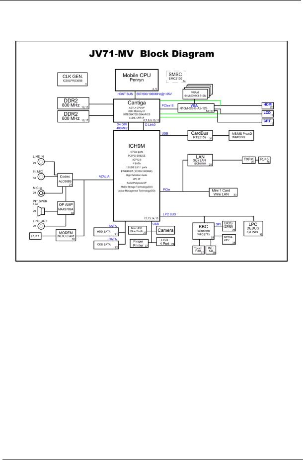
System Block Diagram
For Aspire 7736/7736Z/7336 Series:
4 |
Chapter 1 |

For Aspire 7540 Series:
Chapter 1 |
5 |
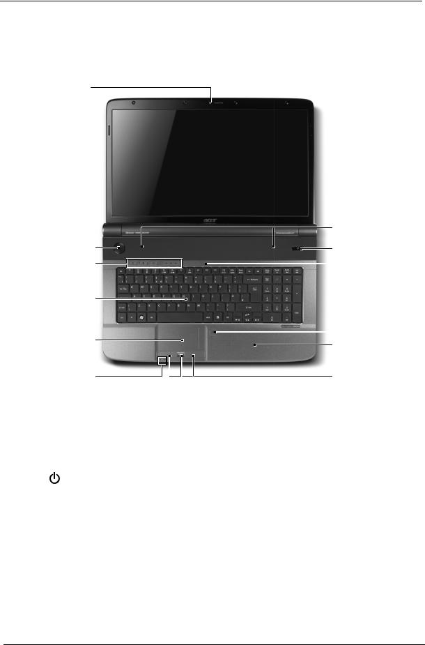
Your Acer Notebook tour
After knowing your computer features, let us show you around your new computer.
Front View
1
2
|
|
|
13 |
|
|
3 |
12 |
|
|
4 |
11 |
|
|
5 |
|
|
|
6 |
10 |
|
|
9 |
|
|
|
|
|
|
|
7 |
8 |
|
|
|
|
# |
Icon |
Item |
Description |
1 |
|
Acer Crystal Eye |
Web camera for video communication. (only for certain models) |
|
|
webcam |
|
|
|
|
|
2 |
|
Display screen |
Also called Liquid-Crystal Display (LCD), displays computer output |
|
|
|
(Configuration may vary by models). |
|
|
|
|
3 |
|
Power button |
Turns the computer on and off. |
|
|
|
|
6 |
Chapter 1 |
# |
Icon |
Item |
Description |
||
4 |
|
|
|
Wireless LAN |
Enables/disables the wireless LAN function. Indicates the status of |
|
|
|
|
communication |
wireless LAN communication. |
|
|
|
|
button/indicator |
|
|
|
|
|
|
|
|
|
|
|
Bluetooth |
Enables/disables the Bluetooth function. Indicates the status of |
|
|
|
|
communication |
Bluetooth communication. (only for certain models) |
|
|
|
|
button/indicator |
|
|
|
|
|
|
|
|
|
|
|
Backup key |
Launches Acer Backup Management for three-step data backup. |
|
|
|
|
|
|
|
|
|
|
HDD |
Indicates when the hard disk drive is active. |
|
|
|
|
|
|
|
|
|
|
Num Lock |
Lights up when Num Lock is activated. |
|
|
|
|
|
|
|
|
|
|
|
|
|
|
|
|
Caps Lock |
Lights up when Caps Lock is activated. |
|
|
|
|
|
|
|
|
|
|
|
|
5 |
|
|
|
Keyboard |
For entering data into your computer. |
|
|
|
|
|
|
6 |
|
|
|
Touchpad |
Touch-sensitive pointing device which functions like a computer |
|
|
|
|
|
mouse. |
|
|
|
|
|
|
7 |
|
|
|
Power1 |
Indicates the computer's power status. |
|
|
|
|
|
|
|
|
|
|
Battery1 |
Indicates the computer's battery status. |
|
|
|
|
|
1. Charging: The light shows amber when the battery is charging. |
|
|
|
|
|
2. Fully charged: The light shows blue when in AC mode. |
|
|
|
|
|
|
8 |
|
|
|
Click buttons |
The left and right buttons function like the left and right mouse |
|
|
|
|
(left and right) |
buttons. |
|
|
|
|
|
|
9 |
|
|
|
Palmrest |
Comfortable support area for your hands when you use the |
|
|
|
|
|
computer. |
|
|
|
|
|
|
10 |
|
|
|
Touchpad toggle |
Turns the internal touchpad on and off. |
|
|
|
|
|
|
11 |
|
|
|
Microphone |
Internal microphone for sound recording. |
|
|
|
|
|
|
12 |
|
|
|
Acer PowerSmart |
Puts your computer into power-saving mode. |
|
|
|
|
key |
|
|
|
|
|
|
|
13 |
|
|
|
Speakers |
Left and right speakers deliver stereo audio output. |
|
|
|
|
|
|
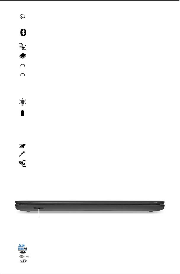
Closed Front View
1
# |
Icon |
Item |
Description |
1 |
|
Multi-in-1 card |
Accepts Secure Digital (SD), MultiMediaCard (MMC), Memory Stick |
|
|
reader |
(MS), Memory Stick PRO (MS PRO), xD-Picture Card (xD). |
|
|
|
Note: Push to remove/install the card. Only one card can operate at |
|
|
|
any given time. |
|
|
|
|
Chapter 1 |
7 |

Left View
|
|
|
|
|
|
|
|
|
|
|
|
|
|
|
|
|
|
|
|
|
|
|
|
|
|
|
|
|
|
|
|
|
|
|
|
|
|
|
|
|
|
|
|
|
|
|
|
|
|
|
|
|
|
|
|
|
|
|
|
|
|
|
|
|
|
|
|
|
|
|
|
|
|
|
|
|
|
|
|
|
|
|
|
|
|
|
|
|
|
|
|
|
|
|
|
|
|
|
|
|
|
|
|
|
|
|
|
|
|
|
|
|
|
|
|
|
|
|
|
|
|
|
|
|
|
|
|
|
|
|
|
|
|
|
|
|
|
|
|
|
|
|
|
|
|
|
|
|
|
|
|
|
|
|
|
|
|
|
|
|
|
|
|
|
|
|
|
|
|
|
|
|
|
|
|
|
|
|
|
|
|
|
|
1 |
2 |
3 |
4 |
5 |
6 |
|
||||||||||||||||
# |
Icon |
Item |
Description |
1 |
|
DC-in jack |
Connects to an AC adapter. |
2Ethernet (RJ-45) Connects to an Ethernet 10/100/1000-based network. port
3 |
|
|
External display |
Connects to a display device |
|
|
|
(VGA) port |
(e.g., external monitor, LCD projector). |
|
|
|
|
|
4 |
HDMI |
HDMI port |
Supports high definition digital video connections. |
|
|
|
|
|
|
5 |
|
|
USB 2.0 port |
Connect to USB 2.0 devices |
|
|
|
|
(e.g., USB mouse, USB camera). |
|
|
|
|
|
6 |
|
|
Line-in jack |
Accepts audio line-in devices (e.g., audio CD player, stereo |
|
|
|
|
walkman, mp3 player) |
|
|
|
|
|
|
|
|
Microphone jack |
Accepts inputs from external microphones. |
|
|
|
|
|
|
|
|
Headphones/ |
Connects to audio line-out devices |
|
|
|
speaker/line-out |
(e.g., speakers, headphones). |
|
|
|
jack with |
|
|
|
|
|
|
|
|
|
|
|
|
|
|
S/PDIF support |
|
8 |
Chapter 1 |
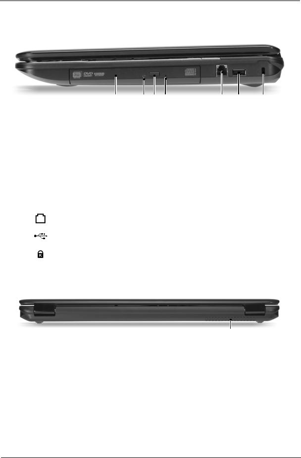
Right View
|
|
|
|
|
|
|
|
|
|
|
|
|
|
|
|
|
|
|
|
|
|
|
|
|
|
|
|
|
|
|
|
|
|
|
|
|
|
|
|
|
|
|
|
|
|
|
|
|
|
|
|
|
|
|
|
|
|
|
|
|
|
|
|
|
|
|
|
|
|
|
|
|
|
|
|
|
|
|
|
|
|
|
|
|
|
|
|
|
|
|
|
|
|
|
|
|
|
|
|
|
|
|
|
|
|
|
|
|
|
|
|
|
|
|
|
|
|
|
|
|
|
|
|
|
|
|
|
1 |
2 3 4 |
5 |
6 |
7 |
||||||||||||||
|
|
|
|
|
|
|
|
|
|
|
|
|
|
|
|
|
|
|
|
|
# |
Icon |
Item |
|
|
|
|
|
|
Description |
|
|
|
|
|
|
|||||
1 |
|
Optical drive |
Internal optical drive; accepts CDs or DVDs. |
|
|
|
||||||||||||||
|
|
|
|
|
|
|
|
|
|
|
|
|
|
|
|
|
|
|
|
|
2 |
|
Optical disk access |
Lights up when the optical drive is active. |
|
|
|
|
|
|
|||||||||||
|
|
indicator |
|
|
|
|
|
|
|
|
|
|
|
|
|
|
|
|
||
|
|
|
|
|
|
|
|
|
|
|
|
|
|
|
|
|
|
|
|
|
3 |
|
Optical drive eject |
Ejects the optical disk from the drive. |
|
|
|
|
|
|
|||||||||||
|
|
button |
|
|
|
|
|
|
|
|
|
|
|
|
|
|
|
|
||
|
|
|
|
|
|
|
|
|
|
|
|
|
|
|
|
|
|
|||
4 |
|
Emergency eject |
Ejects the optical drive tray when the computer is turned off. |
|||||||||||||||||
|
|
hole |
Note: Insert a paper clip to the emergency eject hole to eject the |
|||||||||||||||||
|
|
|
|
|
optical drive tray when the computer is off. |
|
|
|
||||||||||||
|
|
|
|
|
|
|
|
|
|
|
|
|
|
|
|
|
|
|
|
|
5 |
|
Modem |
Connects to a phone line. |
|
|
|
|
|
|
|
|
|
||||||||
|
|
(RJ-11) port |
|
|
|
|
|
|
|
|
|
|
|
|
|
|
|
|
||
|
|
|
|
|
|
|
|
|
|
|
|
|
|
|
|
|
|
|
|
|
6 |
|
USB 2.0 port |
Connect to USB 2.0 devices |
|
|
|
|
|
|
|
|
|
||||||||
|
|
|
|
|
(e.g., USB mouse, USB camera). |
|
|
|
|
|
|
|
|
|
||||||
|
|
|
|
|
|
|
|
|
|
|
|
|
|
|
|
|
|
|||
7 |
|
Kensington lock slot |
Connects to a Kensington-compatible computer security lock. |
|||||||||||||||||
|
|
|
|
|
|
|
|
|
|
|
|
|
|
|
|
|
|
|
|
|
Rear View
|
|
|
|
|
|
|
1 |
||
|
|
|
|
|
# |
Item |
Description |
||
1 |
Ventilation slots |
Enable the computer to stay cool, even after prolonged use. |
||
|
|
|
|
|
Chapter 1 |
9 |
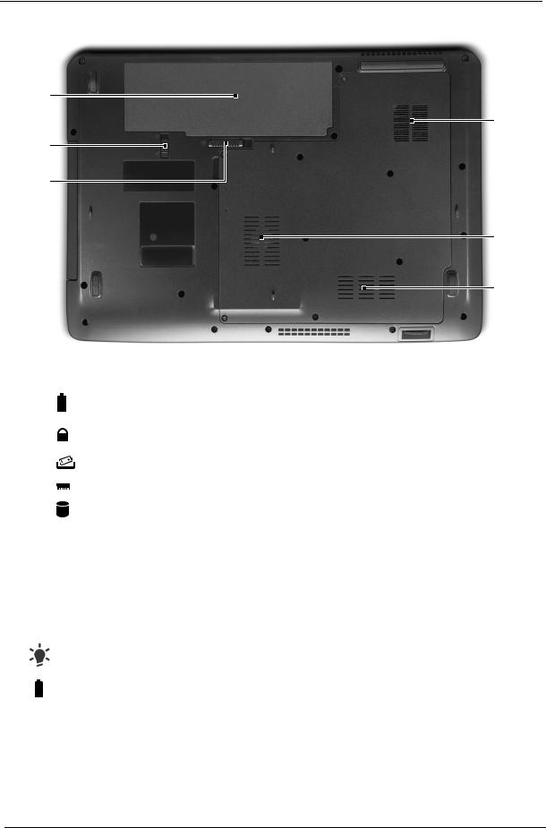
Bottom View
1
6
2
3
5
4
# |
Icon |
Item |
Description |
||
1 |
|
|
|
Battery bay |
Houses the computer's battery pack. |
|
|
|
|
|
|
|
|
|
|
|
|
2 |
|
|
|
Batter Lock |
Locks the battery in position. |
|
|
|
|
|
|
3 |
|
|
|
Battery release latch |
Releases the battery for removal. |
|
|
|
|
|
|
4 |
|
|
|
Memory compartment |
Houses the computer's main memory. |
|
|
|
|
|
|
5 |
|
|
|
Hard disk bay |
Houses the computer's hard disk (secured with screws). |
|
|
|
|
|
|
6 |
|
|
|
Ventilation slots and cooling fan |
Enable the computer to stay cool, even after prolonged use. |
|
|
|
|
|
Note: Do not cover or obstruct the opening of the fan. |
|
|
|
|
|
|
Indicators
The computer has several easy-to-read status indicators.
|
|
Icon |
Function |
|
Description |
|
|
|
Power |
Indicates the computer's power status. |
|
|
|
|
|
|
|
|
|
|
Battery |
Indicates the computer's battery status. |
|
|
|
|
|
1. |
Charging: The light shows amber when the battery is charging. |
|
|
|
|
2. |
Fully charged: The light shows blue when in AC mode. |
|
|
|
|
|
|
NOTE: 1. Charging: The light shows amber when the battery is charging. 2. Fully charged: The light shows green when in AC mode.
10 |
Chapter 1 |
Easy-Launch Buttons
Located on the left of the keyboard are the application buttons. These buttons are called easy-launch buttons. They are: WLAN, Bluetooth and Backup.
Icon |
Function |
Description |
|
Wireless LAN |
Enables/disables the wireless LAN function. Indicates the |
|
communication button/ |
status of wireless LAN communication. |
|
indicator |
|
|
|
|
|
Bluetooth communication |
Enables/disables the Bluetooth function. Indicates the |
|
button/indicator |
status of Bluetooth communication. (only for certain |
|
|
models) |
|
|
|
|
Backup key |
Launches Acer Backup Management for three-step data |
|
|
backup. |
|
|
|
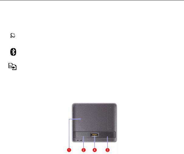
Touchpad Basics (with fingerprint reader)
The following items show you how to use the touchpad with Acer Bio-Protection fingerprint reader.
•Move your finger across the touchpad (2) to move the cursor.
•Press the left (1) and right (4) buttons located beneath the touchpad to perform selection and execution functions. These two buttons are similar to the left and right buttons on a mouse. Tapping on the touchpad is the same as clicking the left button.
•Use Acer Bio-Protection fingerprint reader (3) supporting Acer FingerNav 4-way control function (only for certain models) to scroll up or down and move left or right a page. This fingerprint reader or button mimics your cursor pressing on the right scroll bar of Windows applications.
Function |
Left button (1) |
Right button (4) |
Main touchpad (2) |
Center button (3) |
|
|
|
|
|
|
|
Execute |
Quickly click |
|
Tap twice (at the same speed |
|
|
|
twice. |
|
as double-clicking a mouse |
|
|
|
|
|
button). |
|
|
|
|
|
|
|
|
Select |
Click once. |
|
Tap once. |
|
|
|
|
|
|
|
|
Drag |
Click and |
|
Tap twice (at the same speed |
|
|
|
hold, then |
|
as double-clicking a mouse |
|
|
|
use finger on |
|
button); rest your finger on the |
|
|
|
the touchpad |
|
touchpad on the second tap |
|
|
|
to drag the |
|
and drag the cursor. |
|
|
|
cursor. |
|
|
|
|
|
|
|
|
|
|
Access |
|
Click once. |
|
|
|
context |
|
|
|
|
|
menu |
|
|
|
|
|
|
|
|
|
|
|
|
|
|
|
|
|
Chapter 1 |
11 |

Function |
Left button (1) |
Right button (4) |
Main touchpad (2) |
Center button (3) |
|
|
|
|
|
Scroll |
|
|
|
Swipe up/down/left/right |
|
|
|
|
using Acer FingerNav 4- |
|
|
|
|
way control function |
|
|
|
|
(Manufacturing option). |
|
|
|
|
|
Touchpad basics (with two-click buttons)
The following items show you how to use the touchpad with two-click buttons.
•Move your finger across the touchpad (1) to move the cursor.
•Press the left (2) and right (3) buttons located beneath the touchpad to perform selection and execution functions. These two buttons are similar to the left and right buttons on a mouse. Tapping on the touchpad is the same as clicking the left button.
Function |
Left button (2) |
Right button (3) |
Main touchpad (1) |
|
|
|
|
Execute |
Quickly click twice. |
|
Tap twice (at the same speed as double-clicking |
|
|
|
a mouse button). |
|
|
|
|
Select |
Click once. |
|
Tap once. |
|
|
|
|
Drag |
Click and hold, then use |
|
Tap twice (at the same speed as double-clicking |
|
finger on the touchpad |
|
a mouse button); rest your finger on the touchpad |
|
to drag the cursor. |
|
on the second tap and drag the cursor. |
|
|
|
|
Access |
|
Click once. |
|
context menu |
|
|
|
|
|
|
|
NOTE: Illustrations are for reference only. The exact configuration of your PC depends on the model purchased.
NOTE: When using the touchpad, keep it — and your fingers — dry and clean. The touchpad is sensitive to finger movement; hence, the lighter the touch, the better the response. Tapping harder will not increase the touchpad's responsiveness.
NOTE: By default, vertical and horizontal scrolling is enabled on your touchpad. It can be disabled under Mouse settings in Windows Control Panel.
12 |
Chapter 1 |
Using the Keyboard
The keyboard has full-sized keys and an embedded numeric keypad, separate cursor, lock, Windows, function and special keys.
Lock Keys and numeric keypad
The keyboard has three lock keys which you can toggle on and off.
Lock key |
Description |
Caps Lock |
When Caps Lock is on, all alphabetic characters typed are |
|
in uppercase. |
|
|
Num Lock |
When Num Lock is on, the numeric keypad is in numeric mode. The keys |
|
function as a calculator (complete with the arithmetic operators +, -, *, and /). |
|
Use this mode when you need to do a lot of numeric data entry. A better solution |
|
would be to connect an external keypad. |
|
|
Scroll Lock <Fn> + |
When Scroll Lock is on, the screen moves one line up or down when you press |
<F12> |
the up or down arrow keys respectively. Scroll Lock does not work with some |
|
applications. |
|
|
The keyboard has a numeric keypad with cursor-control keys.
Desired access |
Num Lock on |
Num Lock off |
Number keys on |
Type numbers in a normal manner. |
|
embedded keypad |
|
|
|
|
|
Cursor-control keys on |
Hold <Shift> while using cursor- |
Hold <Fn> while using cursor- |
embedded keypad |
control keys. |
control keys. |
|
|
|
Main keyboard keys |
Hold <Fn> while typing letters on |
Type the letters in a normal |
|
embedded keypad. |
manner. |
|
|
|
Chapter 1 |
13 |
Windows Keys
The keyboard has two keys that perform Windows-specific functions.
|
|
|
Key |
Description |
|
|
|
Windows |
Pressed alone, this key has the same effect as clicking on the Windows Start |
|
|
|
key |
button; it launches the Start menu. |
|
|
|
|
It can also be used with other keys to provide a variety of functions: |
|
|
|
|
< >: Open or close the Start menu |
|
|
|
|
< > + <D>: Display the desktop |
|
|
|
|
< > + <E>: Open Windows Explore |
|
|
|
|
< > + <F>: Search for a file or folder |
|
|
|
|
< > + <G>: Cycle through Sidebar gadgets |
|
|
|
|
< > + <L>: Lock your computer (if you are connected to a network domain), or |
|
|
|
|
switch users (if you're not connected to a network domain) |
|
|
|
|
< > + <M>: Minimizes all windows |
|
|
|
|
< > + <R>: Open the Run dialog box |
|
|
|
|
< > + <T>: Cycle through programs on the taskbar |
|
|
|
|
< > + <U>: Open Ease of Access Center |
|
|
|
|
< > + <X>: Open Windows Mobility Center |
|
|
|
|
< > + <BREAK>: Display the System Properties dialog box |
|
|
|
|
< > + <SHIFT+M>: Restore minimized windows to the desktop |
|
|
|
|
< > + <TAB>: Cycle through programs on the taskbar by using Windows Flip 3- |
|
|
|
|
D |
|
|
|
|
< > + <SPACEBAR>: Bring all gadgets to the front and select Windows |
|
|
|
|
Sidebar |
|
|
|
|
<CTRL> + < > + <F>: Search for computers (if you are on a network) |
|
|
|
|
<CTRL> + < > + <TAB>: Use the arrow keys to cycle through programs on the |
|
|
|
|
taskbar by using Windows Flip 3-D |
|
|
|
|
Note: Depending on your edition of Windows Vista, some shortcuts may not |
|
|
|
|
function as described. |
|
|
|
|
|
|
|
|
Application |
This key has the same effect as clicking the right mouse button; it opens the |
|
|
|
||
|
|
|
key |
application's context menu. |
|
|
|
||
|
|
|
|
|
14 |
Chapter 1 |
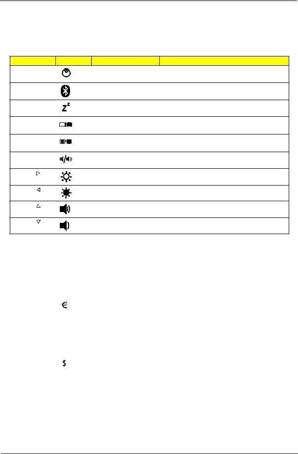
Hot Keys
The computer employs hotkeys or key combinations to access most of the computer’s controls like screen brightness, volume output and the BIOS utility.
To activate hot keys, press and hold the <Fn> key before pressing the other key in the hotkey combination.
Hotkey |
|
Icon |
Function |
Description |
<Fn> + <F2> |
|
System property |
Starts System Property for displaying system |
|
|
|
|
|
information. |
<Fn> + <F3> |
|
Bluetooth |
Enables/disables the Bluetooth function. |
|
<Fn> + <F4> |
|
Sleep |
Puts the computer in Sleep mode. |
|
<Fn> + <F5> |
|
Display toggle |
Switches display output between the display |
|
|
|
|
|
screen, external monitor (if connected) and both. |
<Fn> + <F6> |
|
Screen blank |
Turns the display screen backlight off to save |
|
|
|
|
|
power. Press any key to return. |
<Fn> + <F8> |
|
Speaker toggle |
Turns the speakers on and off. |
|
<Fn> + < |
> |
|
Brightness up |
Increases the screen brightness. |
<Fn> + < |
> |
|
Brightness down |
Decreases the screen brightness. |
<Fn> + < |
> |
|
Volume up |
Increases the sound volume. |
<Fn> + < |
> |
|
Volume down |
Decreases the sound volume. |
Special Key (only for certain models)
You can locate the Euro symbol and the US dollar sign at the upper-center and/or bottom-right of your keyboard.
The Euro symbol
1.Open a text editor or word processor.
2.Either press < > on the keyboard, or hold <Alt Gr> and then press the <5> key at the upper-center of the keyboard.
NOTE: Some fonts and software do not support the Euro symbol. Please refer to www.microsoft.com/ typography/faq/faq12.htm for more information.
The US dollar sign
1.Open a text editor or word processor.
2.Either press < > at the bottom-right of the keyboard, or hold <Shift> and then press the <4> key at the upper-center of the keyboard.
NOTE: This function varies according to the language settings.
Chapter 1 |
15 |
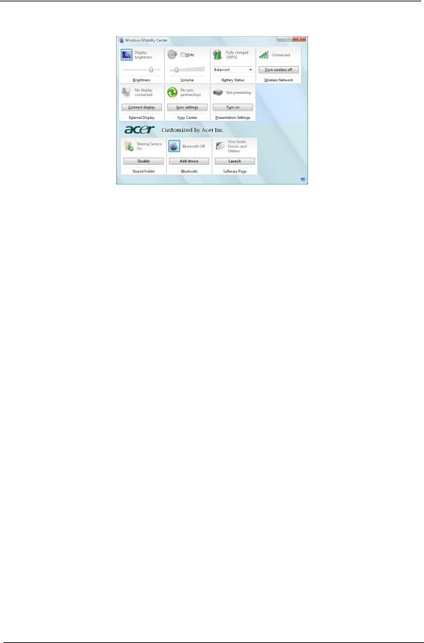
Windows Mobility Center
The Windows Mobility Center collects key mobile-related system settings in one easy-to-find place, so you can quickly configure your Acer system to fit the situation as you change locations, networks or activities. Settings include display brightness, volume, power plan, wireless networking on/off, external display settings, synchronization status and presentation settings.
Windows Mobility Center also includes Acer-specific settings like sharing folders overview/sharing service on or off, Bluetooth Add Device (if applicable), and a shortcut to the Acer user guide, drivers and utilities.
To launch Windows Mobility Center:
q Use the shortcut key < > + <X>.
q Start Windows Mobility Center from the Control panel.
q Start Windows Mobility Center from the Accessories program group in the Start menu.
qLaunch Windows Mobility Center by right-clicking  in the system tray and select Windows Mobility Center.
16 |
Chapter 1 |
Using the System Utilities
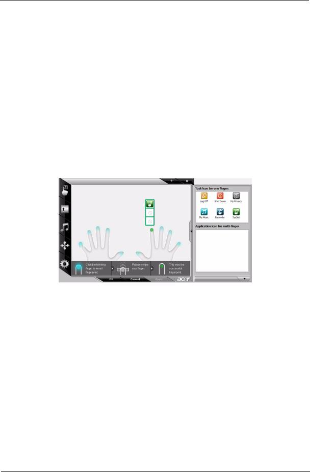
Acer Bio-Protection (only for certain models)
Acer Bio-Protection Fingerprint Solution is a multi-purpose fingerprint software package integrated with the Microsoft Windows operating system. Utilizing the uniqueness of one's fingerprint features, Acer BioProtection Fingerprint Solution has incorporated protection against unauthorized access to your computer with centralized password management with Password Bank, easy music player launching with Acer MusicLaunch, secure Internet favorites via Acer MyLaunch, and fast application/website launching and login with Acer FingerLaunch, while Acer ProfileLaunch can launch up to three applications/websites from a single finger swipe.
Acer Bio-Protection Fingerprint Solution also allows you to navigate through web browsers and documents using Acer FingerNav. With Acer Bio-Protection Fingerprint Solution, you can now enjoy an extra layer of protection for your personal computer, as well as the convenience of accessing your daily tasks with a simple swipe of your finger!
For more information refer to the Acer Bio-Protection help files.
Chapter 1 |
17 |
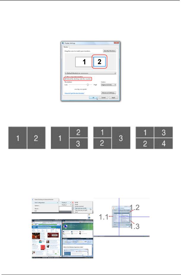
Acer GridVista (dual-display compatible)
NOTE: This feature is only available on certain models.
To enable the dual monitor feature of the notebook, first ensure that the second monitor is connected, then select Start, Control Panel, Display and click on Settings. Select the secondary monitor (2) icon in the display box and then click the check box Extend my windows desktop onto this monitor. Finally, click Apply to confirm the new settings and click OK to complete the process.
Acer GridVista is a handy utility that offers four pre-defined display settings so you can view multiple windows on the same screen. To access this function, please go to Start>All Programs and click on Acer GridVista. You may choose any one of the four display settings indicated below:
Double (vertical), Triple (primary at left), Triple (primary at right), or Quad Acer Gridvista is dual-display compatible, allowing two displays to be partitioned independently.
Acer Gridvista is dual-display compatible, allowing two displays to be partitioned independently. AcerGridVista is simple to set up:
1.Run Acer GridVista and select your preferred screen configuration for each display from the task bar.
2.Drag and drop each window into the appropriate grid.
3.Enjoy the convenience of a well-organized desktop.
NOTE: Please ensure that the resolution setting of the second monitor is set to the manufacturer's recommended value.
18 |
Chapter 1 |

Hardware Specifications and Configurations
Processor
|
Item |
|
Specification |
||
CPU type |
|
|
Aspire 7736/7336 Series: |
||
|
|
|
|
Intel® Core™2 Duo P8800 PGA (2.66 GHz) |
|
|
|
|
|
Intel® Core™2 Duo T6500 PGA (2.1 GHz) |
|
|
|
|
|
Intel Celeron 900 PGA (2.2 GHz) |
|
|
|
|
Aspire 7736Z Series: Intel Pentium Dual-Core T4200 PGA (2.0 GHz) |
||
|
|
|
Aspire 7540 Series: AMD Turion II M520 2.3 GHz |
||
|
|
|
|
AMD Athlon II M320 2.1 GHz |
|
|
|
|
|
AMD Turion M620 2.5 GHz |
|
|
|
|
|
|
|
Core logic |
|
|
Aspire 7736/7736Z/7336 Series: Mobile Intel® PM45/GM45/GL40 |
||
|
|
|
Express Chipset |
||
|
|
|
Aspire 7540 Series: AMD M880G Chipset |
||
|
|
|
|
|
|
CPU package |
|
|
Aspire 7736/7736Z/7336 Series: 478-pin micro-FCPGA |
||
|
|
|
Aspire 7540 Series: Socket S1 |
||
|
|
|
|
|
|
CPU core voltage |
Aspire 7736/7736Z/7336 Series:: 1.0375V to 1.3V |
||||
|
|
|
Aspire 7540 Series: 1.35V to 1.5V |
||
|
|
|
|
|
|
CPU Fan True Value Table |
|
|
|
||
|
|
|
|
|
|
DTS(degree C) |
|
Fan Speed (rpm) |
Acoustic Level (dBA) |
|
|
45-50 |
|
0-3000 |
|
29 |
|
|
|
|
|
|
|
55-66 |
|
0-3300 |
|
33 |
|
|
|
|
|
|
|
68-74 |
|
3300-3800 |
|
38 |
|
|
|
|
|
|
|
78-83 |
|
3800-4100 |
|
40 |
|
|
|
|
|
|
|
86-91 |
|
4100-4800 |
|
40 |
|
|
|
|
|
|
|
Throttling 50%: On= 99 C; OFF=93 C
OS shut down at 105 C; H/W shot down at 110 .C
BIOS
|
Item |
Specification |
|
|
BIOS vendor |
Phoenix |
|
|
|
|
|
|
BIOS Version |
Aspire 7736/7736Z/7336 Series: v1.16 |
|
|
|
|
|
|
|
Aspire 7540 Series: v1.07 |
|
|
|
|
|
|
System Memory |
|
|
|
|
|
|
|
Item |
Specification |
|
|
Memory controller |
Built-in |
|
|
|
|
|
|
Memory size |
0MB (no on-board memory) |
|
|
|
|
|
|
DIMM socket number |
2 sockets |
|
|
|
|
|
|
Supports memory size per socket |
2048MB |
|
|
|
|
|
|
Supports maximum memory size |
4GB for 64bit OS (with two 2GB SODIMM) |
|
|
|
|
|
|
Supports DIMM type |
DDR 2 Synchronous DRAM |
|
|
|
|
|
|
Supports DIMM Speed |
667 MHz |
|
|
|
|
|
|
Supports DIMM voltage |
1.5V |
|
|
|
|
|
|
Supports DIMM package |
240-pin soDIMM |
|
|
|
|
|
|
|
|
|
Chapter 1 |
19 |

System Memory
Item |
Specification |
Memory module combinations |
You can install memory modules in any combinations as long as |
|
|
they match the above specifications. |
|
|
|
|
Memory Combinations |
|
|
|
|
|
Slot 1 |
Slot 2 |
Total Memory |
0MB |
1024MB |
1024MB |
|
|
|
0MB |
2048MB |
2048MB |
|
|
|
1024MB |
0MB |
1024MB |
|
|
|
1024MB |
1024MB |
2048MB |
|
|
|
1024MB |
2048MB |
3072MB |
|
|
|
2048MB |
0MB |
2048MB |
|
|
|
2048MB |
1024MB |
3072MB |
|
|
|
2048MB |
2048MB |
4096MB |
|
|
|
0MB |
4096MB |
4096MB |
|
|
|
4096MB |
0MB |
4096MB |
|
|
|
NOTE: Above table lists some system memory configurations. You may combine DIMMs with various capacities to form other combinations. On above table, the configuration of slot 1 and slot 2 could be reversed.
Item |
Specification |
LAN Chipset |
Broadcom BCM5784 |
|
|
Supports LAN protocol |
10/100/1000 Mbps |
|
|
LAN connector type |
RJ45 |
|
|
LAN connector location |
Left side |
|
|
Features |
Integrated 10/100 BASE-T transceiver |
|
Wake on LAN support compliant with ACPI 1.0b/2.0/3.0 |
|
PCI v2.2 |
|
|
Bluetooth Interface |
|
|
|
Item |
Specification |
Chipset |
Foxconn Bluetooth BRM 2046 BT2.1 |
|
|
Data throughput |
723 bps (full speed data rate) |
|
|
Protocol |
Bluetooth 2.1 |
|
|
Interface |
USB |
|
|
Connector type |
USB |
|
|
20 |
Chapter 1 |

Wireless Module 802.11b/g/n
Item |
Specification |
Chipset |
Aspire 7736 series: Lan Intel WLAN 512AN_HMWG |
|
Shirley Peak 5100 MM#895373;Lan Intel WLAN |
|
512AN_MMWG Shirley Peak 5100 MM#895361 |
|
Aspire 7736Z Series: Foxconn Wirelss LAN Atheros HB95 |
|
1x1 BG (HM) |
|
Aspire 7336 series: QMI Wireless LAN Atheros HB93 1x2 |
|
BGN (HM) EM306 |
|
Aspire 7540 Series: QMI Wireless LAN Atheros HB93 1x2 |
|
BGN (HM) EM306; Foxconn Wirelss LAN Atheros HB95 |
|
1x1 BG (HM) |
|
|
Data throughput |
11~54 Mbps, up to 270 Mbps for Draft-N |
|
|
Protocol |
802.11b+g, Draft-N |
|
|
Interface |
PCI bus (mini PCI socket for wireless module) |
|
|
Hard Disk Drive
Item |
|
|
|
|
|
Vendor & Model Name |
|
HGST 2.5" |
HGST 2.5" |
HGST 2.5" |
WD 2.5" WD5000BEVT- |
|
|
HTS545016B9A300 |
HTS545025B9A300 |
HTS545032B9A300 |
22ZAT0 ML250 SATA LF |
|
|
Panther B SATA LF F/ |
Panther B SATA LF F/ |
Panther B SATA LF F/W: |
F/W:01.01A01 |
|
|
W:C60F |
W:C60F |
C60F |
|
|
|
|
WD 2.5" WD2500BEVT- |
|
|
|
|
|
22ZCT0 ML160 SATA LF |
|
|
|
|
|
F/W:11.01A11 |
|
|
Capacity (MB) |
|
160000 |
250000 |
320000 |
500000 |
|
|
|
|
|
|
Bytes per sector |
|
512 |
512 |
512 |
512 |
|
|
|
|
|
|
Data heads |
|
3/4 |
2 |
3 |
4 |
|
|
|
|
|
|
Drive Format |
|
|
|
|
|
|
|
|
|
|
|
Disks |
|
2 |
2 |
2 |
2 |
|
|
|
|
|
|
Spindle speed (RPM) |
|
5400 RPM |
5400 RPM |
5400 RPM |
5400 RPM |
|
|
|
|
|
|
Performance Specifications |
|
|
|
||
|
|
|
|
|
|
Buffer size |
|
8MB |
8MB |
8MB |
8MB |
|
|
|
|
|
|
Interface |
|
SATA |
SATA |
SATA |
SATA |
|
|
|
|
|
|
Max. media transfer |
|
540 |
875 |
875 |
875 |
rate (disk-buffer, |
|
|
(Max. 3.0 Gbit/s Buffer- |
(Max. 3.0 Gbit/s Buffer- |
(Max. 3.0 Gbit/s Buffer- |
Mbytes/s) |
|
|
host data transfer) |
host data transfer) |
host data transfer) |
|
|
|
|
|
|
DC Power Requirements |
|
|
|
|
|
|
|
|
|
|
|
Voltage tolerance |
|
5V(DC) +/- 5% |
5V(DC) +/- 5% |
5V(DC) +/- 5% |
5V(DC) +/- 5% |
|
|
|
|
|
|
Optical Disc Drive
Item |
|
Specification |
|
Vendor & model name |
HLDS Super-Multi DRIVE 12.7mm Tray DL 8X GT30N LF |
||
|
TOSHIBA Super-Multi DRIVE 12.7mm Tray DL 8X TS-L633C LF |
||
|
|
|
|
Performance Specification |
With CD Diskette |
|
With DVD Diskette |
|
|
|
|
Transfer rate (KB/sec) |
Sustained: |
|
Sustained: |
|
Max 3.6Mbytes/sec |
|
Max 10.08Mbytes/sec |
|
|
|
|
Buffer Memory |
2MB |
|
|
|
|
|
|
Interface |
SATA |
|
|
|
|
|
|
Chapter 1 |
21 |

Optical Disc Drive
Item |
|
|
|
Specification |
|
|
|
Applicable disc format |
|
Applicable disc format |
|
|
|||
|
|
CD: CD-DA, CD-ROM, CD-ROM XA, Photo CD (multi-session), Video |
|
||||
|
|
CD, Cd-Extra (CD+), CD-text |
|
|
|||
|
|
DVD: DVD-VIDEO, DVD-ROM, DVD-R (3.9GB, 4.7GB) DVD-R DL, |
|
||||
|
|
DVD-RW, DVD-RAM, DVD+R, DVD+R DL, DVD+RW |
|
||||
|
|
CD: |
|
|
|
|
|
|
|
CD-DA (Red Book) - Standard Audio CD & CD-TEXT |
|
||||
|
|
CD-ROM (Yellow Book Mode1 & 2) - Standard Data |
|
||||
|
|
CD-ROM XA (Mode2 Form1 & 2) - Photo CD, Multi-Session |
|
||||
|
|
CD-I (Green Book, Mode2 Form1 & 2, Ready, Bridge) |
|
||||
|
|
CD-Extra/ CD-Plus (Blue Book) - Audio & Text/Video |
|
||||
|
|
Video-CD (White Book) - MPEG1 Video |
|
|
|||
|
|
CD-R (Orange Book Part) |
|
|
|||
|
|
CD-RW & HSRW (Orange Book Part Volume1 & Volume 2 |
|
||||
|
|
Super Audio CD (SACD) Hybrid type |
|
|
|||
|
|
US & US+ RW |
|
|
|
|
|
|
|
DVD: |
|
|
|
|
|
|
|
DVD-ROM (Book 1.02), DVD-Dual |
|
|
|||
|
|
DVD-Video (Book 1.1) |
|
|
|||
|
|
DVD-R (Book 1.0, 3.9G) |
|
|
|||
|
|
DVD-R (Book 2.0, 4.7G) - General & Authoring |
|
|
|||
|
|
DVD+R (Version 1.0) |
|
|
|||
|
|
DVD+RW |
|
|
|
|
|
|
|
DVD-RW (Non CPRM & CPRM) |
|
|
|||
|
|
DVD°”R Dual |
|
|
|
|
|
|
|
|
|
|
|
|
|
Loading mechanism |
|
Load: Manual |
|
|
|
|
|
|
|
Release: (a) Electrical Release (Release Button) |
|
|
|||
|
|
(b) Release by ATAPI command |
|
|
|||
|
|
(c) Emergency Release |
|
|
|||
|
|
|
|
|
|
|
|
Power Requirement |
|
|
|
|
|
|
|
|
|
|
|
|
|
|
|
Input Voltage |
|
5 V +/- 5% (Operating) |
|
|
|||
|
|
|
|
|
|
|
|
Blu-Ray Disc Drive |
|
|
|
|
|
|
|
|
|
|
|
|
|
|
|
Item |
|
|
Specification |
|
|
|
|
Vendor & model name |
HLDS BD COMBO DRIVE TRAY DL 4X CT10 LF |
|
|
|
|||
|
SONY BD COMBO 12.7mm Tray DL 4X BC-5500S LF |
|
|
||||
|
|
|
|
|
|
|
|
Performance |
With CD Disc |
|
With DVD Disc |
|
With Blu-ray Disc |
|
|
Specification |
|
|
|
|
|
|
|
|
|
|
|
|
|
|
|
Transfer rate (KB/sec) |
Sustained: |
|
Sustained: |
|
Sustained: |
|
|
|
Max 3.6Mbytes/sec |
|
Max 10.08Mbytes/sec |
|
Max 11 Mbytes/sec |
|
|
|
|
|
|
|
|
|
|
Buffer Memory |
2MB |
|
|
|
4.5 MB |
|
|
|
|
|
|
|
|
|
|
Interface |
SATA |
|
|
|
|
|
|
|
|
|
|
|
|
|
|
22 |
Chapter 1 |
Loading...