


 Loading...
Acer Aspire 4252/4552/4552G
Service Guide
Service guide files and updates are available on the ACER/CSD web; for more information, please refer to http://csd.acer.com.tw
PRINTED IN TAIWAN

Revision History
Please refer to the table below for the updates made on this service guides.
Date |
Chapter |
Updates |
|
|
|
|
|
|
|
|
|
|
|
|
II

Copyright
Copyright © 2010 by Acer Incorporated. All rights reserved. No part of this publication may be reproduced, transmitted, transcribed, stored in a retrieval system, or translated into any language or computer language, in any form or by any means, electronic, mechanical, magnetic, optical, chemical, manual or otherwise, without the prior written permission of Acer Incorporated.
Disclaimer
The information in this guide is subject to change without notice.
Acer Incorporated makes no representations or warranties, either expressed or implied, with respect to the contents hereof and specifically disclaims any warranties of merchantability or fitness for any particular purpose. Any Acer Incorporated software described in this manual is sold or licensed "as is". Should the programs prove defective following their purchase, the buyer (and not Acer Incorporated, its distributor, or its dealer) assumes the entire cost of all necessary servicing, repair, and any incidental or consequential damages resulting from any defect in the software.
Acer is a registered trademark of Acer Corporation. Intel is a registered trademark of Intel Corporation.
Other brand and product names are trademarks and/or registered trademarks of their respective holders.
III

Conventions
The following conventions are used in this manual:
SCREEN MESSAGES |
Denotes actual messages that appear |
|
on screen. |
|
|
NOTE |
Gives bits and pieces of additional |
|
information related to the current |
|
topic. |
|
|
WARNING |
Alerts you to any damage that might |
|
result from doing or not doing specific |
|
actions. |
|
|
CAUTION |
Gives precautionary measures to |
|
avoid possible hardware or software |
|
problems. |
|
|
IMPORTANT |
Reminds you to do specific actions |
|
relevant to the accomplishment of |
|
procedures. |
|
|
NOTE: This symbol where placed in the Service Guide designates a component that should be recycled according to the local regulations.
IV

Preface
Before using this information and the product it supports, please read the following general information.
1.This Service Guide provides you with all technical information relating to the BASIC CONFIGURATION decided for Acer's "global" product offering. To better fit local market requirements and enhance product competitiveness, your regional office MAY have decided to extend the functionality of a machine (e.g. add-on card, modem, or extra memory capability). These LOCALIZED FEATURES will NOT be covered in this generic service guide. In such cases, please contact your regional offices or the responsible personnel/channel to provide you with further technical details.
2.Please note WHEN ORDERING FRU PARTS, that you should check the most up-to-date information available on your regional web or channel. If, for whatever reason, a part number change is made, it will not be noted in the printed Service Guide. For ACER-AUTHORIZED SERVICE PROVIDERS, your Acer office may have a DIFFERENT part number code to those given in the FRU list of this printed Service Guide. You MUST use the list provided by your regional Acer office to order FRU parts for repair and service of customer machines.
V

VI

Table of Contents
System Specifications |
1 |
Features . . . . . . . . . . . . . . . . . . . . . . . . . . . . . . . . . . . . . . . . . . . . . . . . . . . . . . . . . . . .1 System Block Diagram . . . . . . . . . . . . . . . . . . . . . . . . . . . . . . . . . . . . . . . . . . . . . . . . .6 Your Acer Notebook tour . . . . . . . . . . . . . . . . . . . . . . . . . . . . . . . . . . . . . . . . . . . . . . .7 Top View . . . . . . . . . . . . . . . . . . . . . . . . . . . . . . . . . . . . . . . . . . . . . . . . . . . . . . . .7 Closed Front View . . . . . . . . . . . . . . . . . . . . . . . . . . . . . . . . . . . . . . . . . . . . . . . . .8 Rear view . . . . . . . . . . . . . . . . . . . . . . . . . . . . . . . . . . . . . . . . . . . . . . . . . . . . . . .9 Left View . . . . . . . . . . . . . . . . . . . . . . . . . . . . . . . . . . . . . . . . . . . . . . . . . . . . . . . .9 Right View . . . . . . . . . . . . . . . . . . . . . . . . . . . . . . . . . . . . . . . . . . . . . . . . . . . . . .10 Base View . . . . . . . . . . . . . . . . . . . . . . . . . . . . . . . . . . . . . . . . . . . . . . . . . . . . . .10 Indicators . . . . . . . . . . . . . . . . . . . . . . . . . . . . . . . . . . . . . . . . . . . . . . . . . . . . . .11 Touchpad Basics . . . . . . . . . . . . . . . . . . . . . . . . . . . . . . . . . . . . . . . . . . . . . . . .12 Using the Keyboard . . . . . . . . . . . . . . . . . . . . . . . . . . . . . . . . . . . . . . . . . . . . . . . . . .13 Lock Keys and embedded numeric keypad . . . . . . . . . . . . . . . . . . . . . . . . . . . .13 Windows Keys . . . . . . . . . . . . . . . . . . . . . . . . . . . . . . . . . . . . . . . . . . . . . . . . . .14 Hot Keys . . . . . . . . . . . . . . . . . . . . . . . . . . . . . . . . . . . . . . . . . . . . . . . . . . . . . . .15
Hardware Specifications and Configurations . . . . . . . . . . . . . . . . . . . . . . . . . . . . . . .16
System Utilities |
31 |
BIOS Setup Utility . . . . . . . . . . . . . . . . . . . . . . . . . . . . . . . . . . . . . . . . . . . . . . . . . . . .31
Navigating the BIOS Utility . . . . . . . . . . . . . . . . . . . . . . . . . . . . . . . . . . . . . . . . .31
Information . . . . . . . . . . . . . . . . . . . . . . . . . . . . . . . . . . . . . . . . . . . . . . . . . . . . .32
Main . . . . . . . . . . . . . . . . . . . . . . . . . . . . . . . . . . . . . . . . . . . . . . . . . . . . . . . . . .33
Security . . . . . . . . . . . . . . . . . . . . . . . . . . . . . . . . . . . . . . . . . . . . . . . . . . . . . . . .34
Boot . . . . . . . . . . . . . . . . . . . . . . . . . . . . . . . . . . . . . . . . . . . . . . . . . . . . . . . . . . .37
Exit . . . . . . . . . . . . . . . . . . . . . . . . . . . . . . . . . . . . . . . . . . . . . . . . . . . . . . . . . . .38
BIOS Flash Utility . . . . . . . . . . . . . . . . . . . . . . . . . . . . . . . . . . . . . . . . . . . . . . . . . . . .39
BIOS Flash Utility . . . . . . . . . . . . . . . . . . . . . . . . . . . . . . . . . . . . . . . . . . . . . . . . . . . .40
DOS Flash Utility . . . . . . . . . . . . . . . . . . . . . . . . . . . . . . . . . . . . . . . . . . . . . . . . .40
WinFlash Utility . . . . . . . . . . . . . . . . . . . . . . . . . . . . . . . . . . . . . . . . . . . . . . . . . .40
Remove HDD/BIOS Password Utilities . . . . . . . . . . . . . . . . . . . . . . . . . . . . . . . . . . . .41
Removing BIOS Passwords: . . . . . . . . . . . . . . . . . . . . . . . . . . . . . . . . . . . . . . . .42
Cleaning BIOS Passwords . . . . . . . . . . . . . . . . . . . . . . . . . . . . . . . . . . . . . . . . .43
Miscellaneous Utilities . . . . . . . . . . . . . . . . . . . . . . . . . . . . . . . . . . . . . . . . . . . . .44
Machine Disassembly and Replacement |
47 |
Disassembly Requirements . . . . . . . . . . . . . . . . . . . . . . . . . . . . . . . . . . . . . . . . . . . |
.47 |
Pre-disassembly Instructions . . . . . . . . . . . . . . . . . . . . . . . . . . . . . . . . . . . . . . |
.48 |
Disassembly Process . . . . . . . . . . . . . . . . . . . . . . . . . . . . . . . . . . . . . . . . . . . . . |
49 |
External Modules Disassembly Process . . . . . . . . . . . . . . . . . . . . . . . . . . . . . . . . . . . |
50 |
External Modules Disassembly Flowchart . . . . . . . . . . . . . . . . . . . . . . . . . . . . . |
50 |
Removing the Battery Pack . . . . . . . . . . . . . . . . . . . . . . . . . . . . . . . . . . . . . . . . |
51 |
Removing the SD Dummy Card . . . . . . . . . . . . . . . . . . . . . . . . . . . . . . . . . . . . . |
52 |
Removing the Keyboard . . . . . . . . . . . . . . . . . . . . . . . . . . . . . . . . . . . . . . . . . . . |
53 |
Removing the ODD Module . . . . . . . . . . . . . . . . . . . . . . . . . . . . . . . . . . . . . . . . |
55 |
Main Unit Disassembly Process . . . . . . . . . . . . . . . . . . . . . . . . . . . . . . . . . . . . . . . . . |
57 |
Main Unit Disassembly Flowchart . . . . . . . . . . . . . . . . . . . . . . . . . . . . . . . . . . . . |
57 |
Removing the Lower Cover . . . . . . . . . . . . . . . . . . . . . . . . . . . . . . . . . . . . . . . . |
58 |
Component Overview . . . . . . . . . . . . . . . . . . . . . . . . . . . . . . . . . . . . . . . . . . . . . |
59 |
Removing the DIMM Modules . . . . . . . . . . . . . . . . . . . . . . . . . . . . . . . . . . . . . . . |
60 |
Removing the WLAN Module . . . . . . . . . . . . . . . . . . . . . . . . . . . . . . . . . . . . . . . |
61 |
Removing the USB Board . . . . . . . . . . . . . . . . . . . . . . . . . . . . . . . . . . . . . . . . . . |
62 |
Removing the RTC Battery . . . . . . . . . . . . . . . . . . . . . . . . . . . . . . . . . . . . . . . . . |
64 |
VII

Table of Contents |
|
Removing the Bluetooth Module . . . . . . . . . . . . . . . . . . . . . . . . . . . . . . . . . . . |
. .65 |
Removing the HDD Module . . . . . . . . . . . . . . . . . . . . . . . . . . . . . . . . . . . . . . |
. .66 |
Removing the LCD Module . . . . . . . . . . . . . . . . . . . . . . . . . . . . . . . . . . . . . . . |
. .68 |
Removing the Thermal Module . . . . . . . . . . . . . . . . . . . . . . . . . . . . . . . . . . . . |
. .70 |
Removing the CPU . . . . . . . . . . . . . . . . . . . . . . . . . . . . . . . . . . . . . . . . . . . . . |
. .72 |
Removing the Mainboard . . . . . . . . . . . . . . . . . . . . . . . . . . . . . . . . . . . . . . . . |
. .73 |
LCD Module Disassembly Process . . . . . . . . . . . . . . . . . . . . . . . . . . . . . . . . . . . . |
. .75 |
LCD Module Disassembly Flowchart . . . . . . . . . . . . . . . . . . . . . . . . . . . . . . . |
. .75 |
Removing the LCD Bezel . . . . . . . . . . . . . . . . . . . . . . . . . . . . . . . . . . . . . . . . |
. .76 |
Removing the Camera Module . . . . . . . . . . . . . . . . . . . . . . . . . . . . . . . . . . . . |
. .78 |
Removing the LCD Panel . . . . . . . . . . . . . . . . . . . . . . . . . . . . . . . . . . . . . . . . |
. .79 |
Remove the LCD Hinges . . . . . . . . . . . . . . . . . . . . . . . . . . . . . . . . . . . . . . . . |
. .80 |
Removing the LVDS Cable . . . . . . . . . . . . . . . . . . . . . . . . . . . . . . . . . . . . . . . |
. .81 |
Removing the WLAN Antennas . . . . . . . . . . . . . . . . . . . . . . . . . . . . . . . . . . . |
. .82 |
LCD Module Assembly Process . . . . . . . . . . . . . . . . . . . . . . . . . . . . . . . . . . . . . . . |
. .83 |
Replacing the WLAN Antennas . . . . . . . . . . . . . . . . . . . . . . . . . . . . . . . . . . . |
. .83 |
Replacing the LVDS Cable . . . . . . . . . . . . . . . . . . . . . . . . . . . . . . . . . . . . . . . |
. .84 |
Replacing the LCD Hinges . . . . . . . . . . . . . . . . . . . . . . . . . . . . . . . . . . . . . . . |
. .85 |
Removing the LCD Panel . . . . . . . . . . . . . . . . . . . . . . . . . . . . . . . . . . . . . . . . |
. .86 |
Replacing the Camera Module . . . . . . . . . . . . . . . . . . . . . . . . . . . . . . . . . . . . |
. .88 |
Replacing the LCD Bezel . . . . . . . . . . . . . . . . . . . . . . . . . . . . . . . . . . . . . . . . |
. .89 |
Main Unit Assembly Process . . . . . . . . . . . . . . . . . . . . . . . . . . . . . . . . . . . . . . . . . |
. .92 |
Replacing the Mainboard . . . . . . . . . . . . . . . . . . . . . . . . . . . . . . . . . . . . . . . . |
. .92 |
Replacing the CPU . . . . . . . . . . . . . . . . . . . . . . . . . . . . . . . . . . . . . . . . . . . . . |
. .94 |
Replacing the Thermal Module . . . . . . . . . . . . . . . . . . . . . . . . . . . . . . . . . . . . |
. .95 |
Replacing the LCD Module . . . . . . . . . . . . . . . . . . . . . . . . . . . . . . . . . . . . . . . |
. .97 |
Replacing the Bluetooth Module . . . . . . . . . . . . . . . . . . . . . . . . . . . . . . . . . . . |
. .99 |
Replacing the HDD Module . . . . . . . . . . . . . . . . . . . . . . . . . . . . . . . . . . . . . . |
.100 |
Removing the RTC Battery . . . . . . . . . . . . . . . . . . . . . . . . . . . . . . . . . . . . . . . |
.103 |
Replacing the USB Board . . . . . . . . . . . . . . . . . . . . . . . . . . . . . . . . . . . . . . . . . |
104 |
Replacing the WLAN Module . . . . . . . . . . . . . . . . . . . . . . . . . . . . . . . . . . . . . . |
105 |
Replacing the DIMM Modules . . . . . . . . . . . . . . . . . . . . . . . . . . . . . . . . . . . . . . |
107 |
Replacing the Lower Cover . . . . . . . . . . . . . . . . . . . . . . . . . . . . . . . . . . . . . . . . |
108 |
External Module Assembly Process . . . . . . . . . . . . . . . . . . . . . . . . . . . . . . . . . . . . . |
109 |
Replacing the ODD Module . . . . . . . . . . . . . . . . . . . . . . . . . . . . . . . . . . . . . . . |
109 |
Replacing the Keyboard . . . . . . . . . . . . . . . . . . . . . . . . . . . . . . . . . . . . . . . . . . |
110 |
Replacing the SD dummy card . . . . . . . . . . . . . . . . . . . . . . . . . . . . . . . . . . . . . |
112 |
Replacing the Battery Pack . . . . . . . . . . . . . . . . . . . . . . . . . . . . . . . . . . . . . . . . |
112 |
Troubleshooting |
113 |
Common Problems . . . . . . . . . . . . . . . . . . . . . . . . . . . . . . . . . . . . . . . . . . . . . . . . . .113
Power On Issue . . . . . . . . . . . . . . . . . . . . . . . . . . . . . . . . . . . . . . . . . . . . . . . .114
No Display Issue . . . . . . . . . . . . . . . . . . . . . . . . . . . . . . . . . . . . . . . . . . . . . . . .115
Random Loss of BIOS Settings . . . . . . . . . . . . . . . . . . . . . . . . . . . . . . . . . . . .116
LCD Failure . . . . . . . . . . . . . . . . . . . . . . . . . . . . . . . . . . . . . . . . . . . . . . . . . . . .117
Built-In Keyboard Failure . . . . . . . . . . . . . . . . . . . . . . . . . . . . . . . . . . . . . . . . .117
Touchpad Failure . . . . . . . . . . . . . . . . . . . . . . . . . . . . . . . . . . . . . . . . . . . . . . .118
Internal Speaker Failure . . . . . . . . . . . . . . . . . . . . . . . . . . . . . . . . . . . . . . . . . .118
HDD Not Operating Correctly . . . . . . . . . . . . . . . . . . . . . . . . . . . . . . . . . . . . . .120
ODD Failure . . . . . . . . . . . . . . . . . . . . . . . . . . . . . . . . . . . . . . . . . . . . . . . . . . .121
Wireless Function Failure . . . . . . . . . . . . . . . . . . . . . . . . . . . . . . . . . . . . . . . . .124
Thermal Unit Failure . . . . . . . . . . . . . . . . . . . . . . . . . . . . . . . . . . . . . . . . . . . . .124
External Mouse Failure . . . . . . . . . . . . . . . . . . . . . . . . . . . . . . . . . . . . . . . . . . .125
Other Failures . . . . . . . . . . . . . . . . . . . . . . . . . . . . . . . . . . . . . . . . . . . . . . . . . .125
Intermittent Problems . . . . . . . . . . . . . . . . . . . . . . . . . . . . . . . . . . . . . . . . . . . . . . . .126
VIII

Table of Contents
Undetermined Problems . . . . . . . . . . . . . . . . . . . . . . . . . . . . . . . . . . . . . . . . . . . . . .126
Post Codes . . . . . . . . . . . . . . . . . . . . . . . . . . . . . . . . . . . . . . . . . . . . . . . . . . . . . . . .127
Jumper and Connector Locations |
131 |
Top View . . . . . . . . . . . . . . . . . . . . . . . . . . . . . . . . . . . . . . . . . . . . . . . . . . . . . |
.131 |
Bottom View . . . . . . . . . . . . . . . . . . . . . . . . . . . . . . . . . . . . . . . . . . . . . . . . . . |
.132 |
Clearing Password Check and BIOS Recovery . . . . . . . . . . . . . . . . . . . . . . . . . . . |
.133 |
Clearing Password Check . . . . . . . . . . . . . . . . . . . . . . . . . . . . . . . . . . . . . . . . |
.133 |
BIOS Recovery by Crisis Disk . . . . . . . . . . . . . . . . . . . . . . . . . . . . . . . . . . . . |
.134 |
FRU (Field Replaceable Unit) List |
135 |
Acer Aspire 4252/4552/4552G Exploded Diagrams . . . . . . . . . . . . . . . . . . . . . . . . .136
LCD Assembly . . . . . . . . . . . . . . . . . . . . . . . . . . . . . . . . . . . . . . . . . . . . . . . . .136
Acer Aspire 4252/4552/4552G FRU List . . . . . . . . . . . . . . . . . . . . . . . . . . . . . .138
Screw List . . . . . . . . . . . . . . . . . . . . . . . . . . . . . . . . . . . . . . . . . . . . . . . . . . . . .138
Model Definition and Configuration |
140 |
Aspire 4252 . . . . . . . . . . . . . . . . . . . . . . . . . . . . . . . . . . . . . . . . . . . . . . . . . . . |
.140 |
Aspire 4552 . . . . . . . . . . . . . . . . . . . . . . . . . . . . . . . . . . . . . . . . . . . . . . . . . . . |
.142 |
Aspire 4552G . . . . . . . . . . . . . . . . . . . . . . . . . . . . . . . . . . . . . . . . . . . . . . . . . |
.148 |
Test Compatible Components |
157 |
Online Support Information |
161 |
Index |
163 |
IX

Table of Contents
X
Chapter 1
System Specifications
Features
Below is a brief summary of the computer’s many features:
NOTE: Items denoted with an (*) are only available for selected models.
Operating system
•Genuine Windows® 7 Home Premium 64-bit
•Genuine Windows® 7 Home Basic 64-bit
CPU and chipset
Aspire 4552 and 4552G
•AMD Phenom™ II quad-core mobile processor N950 (2 MB L2 cache, 2.10 GHz, DDR3 1333 MHz, 35 W)
•AMD Phenom™ II triple-core mobile processor N850 (1.5 MB L2 cache, 2.20 GHz, DDR3 1333 MHz, 35 W)
•AMD Phenom™ II dual-core mobile processor N620/N640 (2 MB L2 cache, 2.80/2.90 GHz, DDR3 1333 MHz, 35 W)
•AMD Turion™ II dual-core mobile processor P540 (2 MB L2 cache, 2.40 GHz, DDR3 1066 MHz, 25 W)
•AMD Athlon™ II dual-core processor P320/P340 (1 MB L2 cache, 2.10/2.20 GHz, DDR3 1066 MHz, 25 W), N350 (1 MB L2 cache, 2.40 GHz, DDR3 1066 MHz, 35 W)
•AMD M880G Chipset
Aspire 4252
•AMD V Series processor V140 (512 KB L2 cache, 2.30 GHz, DDR3 1066 MHz, 25 W)
•AMD M880G Chipset
System memory
•Dual-channel DDR3 SDRAM support:
• Up to 4 GB of DDR3 system memory, upgradable to 8 GB using two soDIMM modules
Display
•14" HD 1366 x 768 pixel resolution, high-brightness (200-nit) Acer CineCrystal™ LED-backlit TFT LCD
•Mercury free, environment friendly
•16:9 aspect ratio
Chapter 1 |
1 |

Graphics
Aspire 4252 and 2552
•ATI Radeon™ HD 4250 Graphics with 256 MB of dedicated system memory, supporting Unified Video Decoder 2 (UVD2), OpenGL® 2.0, OpenEXR High Dynamic-Range (HDR) technology, Shader Model 4.1, Microsoft® DirectX® 10.1
Aspire 4552G
•ATI Mobility Radeon™ HD 5470 with up to 3579 MB of HyperMemory™ (512 MB of dedicated DDR3 VRAM, up to 3067 MB of shared system memory), supporting Unified Video Decoder (UVD), OpenEXR High Dynamic-Range (HDR) technology, Shader Model 5.0, Microsoft® DirectX® 11, OpenGL® 3.1, OpenCL™ 1.1
•Dual independent display support
•16.7 million colors
•External resolution / refresh rate:
•VGA port up to 2048 x 1536: 85 Hz
•HDMI™ port up to 1920 x 1080: 60 Hz
•MPEG-2/DVD decoding
•VC-1 and H.264 (AVC) decoding
•HDMI™ (High-Definition Multimedia Interface) with HDCP (High-bandwidth Digital Content Protection) support
Audio
•Built-in speaker
•High-definition audio support
•Built-in microphone
•MS-Sound compatible
Storage
•Hard disk drive
•160/250/320/500/640/750 GB or larger
•Multi-in-1 card reader, supporting:
•Secure Digital™ (SD) Card and MultiMediaCard™ (MMC)
Webcam
•Acer Video Conference, featuring:
• Acer Crystal Eye 1.3 MP webcam, 1280 x 1024 resolution
2 |
Chapter 1 |

Wireless and networking
•WLAN:
•Acer InviLink™ Nplify™ 802.11b/g/n Wi-Fi CERTIFIED™
•Acer InviLink™ 802.11b/g Wi-Fi CERTIFIED™802.11b/g/n Wi-Fi CERTIFIED™
•Supporting Acer SignalUp™ wireless technology
•WPAN:
•Bluetooth® 3.0+HS
•Bluetooth® 2.1+EDR
•LAN: Gigabit Ethernet, Wake-on-LAN ready
Privacy control
•BIOS user, supervisor, HDD passwords
•Kensington lock slot
Dimensions and weight
•Dimensions
•341 (W) x 264.5 (D) x 26.7/33.5 (H) mm (13.43 x 10.41 x 1.05/1.32 inches)
•Weight
•2.5 kg (5.51 lbs.) with 6-cell battery pack
Power adapter and battery
•ACPI 3.0 CPU power management standard: supports Standby and Hibernation power-saving modes
Power adapter
Aspire 4252 and 4552
•3-pin 65 W AC adapter:·
•·108 (W) x 46 (D) x 29.5 (H) mm (4.25 x 1.81 x 1.16 inches)
•·225 g (0.49 lbs.) with 180 cm DC cable
Aspire 4552G
•3-pin 65 W AC adapter:·
•133 (W) x 59 (D) x 31 (H) mm (5.23 x 2.32 x 1.22 inches)
•390 g (0.86 lbs.) with 180 cm DC cable
Battery
•48 Wh 4400 mAh 6-cell Li-ion standard battery pack
•Battery life: 3 hours
•ENERGY STAR®
Aspire 4552G Only
•Acer QuicCharge™ technology:
•80% charge in 1 hour
•2-hour rapid charge system-off
Chapter 1 |
3 |

Input and control
•Keyboard
•86-/87-/91-key Acer FineTip keyboard with international language support
•Touchpad
•Multi-gesture touchpad, supporting two-finger scroll, pinch, rotate, flip
•Media keys
•Media control keys (printed on keyboard): play/pause, stop, previous, next, volume up, volume down
I/O interface
•2-in-1 card reader (SD™, MMC)
•Three USB 2.0 ports
•HDMI™ port with HDCP support
•External display (VGA) port
•Headphone/speaker/line-out jack
•Microphone-in jack
•Ethernet (RJ-45) port
•DC-in jack for AC adapter
Software
•Productivity
•Acer Backup Manager
•Acer ePower Management
•Acer eRecovery Management
•Adobe® Flash® Player 10.1
•Adobe® Reader® 9.1
•eSobi™
•Microsoft® Office 2010 preloaded (purchase a product key to activate)
•Microsoft® Office Starter 2010
•Norton™ Online Backup
•Security
•McAfee® Internet Security Suite Trial
•MyWinLocker®
•Multimedia
•Cyberlink® PowerDVD™
•NTI Media Maker™
•Gaming
•Oberon GameZone
•WildTangent®
•Communication and ISP
4 |
Chapter 1 |

•Acer Crystal Eye
•Microsoft® Silverlight™
•Skype™
•Windows Live™ Essentials — Wave 3.2 (Mail, Photo Gallery, Live ™ Messenger, Movie Maker, Writer)
•Web links and utilities
•Acer Accessory Store
•Acer Identity Card
•Acer Registration
•Acer Updater
•eBay® shortcut 2009
•Netflix shortcut
Optional Items
•1/2/4 GB DDR3 soDIMM module
•6-cell Li-ion battery pack
•3-pin 90 W AC adapter
Warranty
•One-year International Travelers Warranty (ITW)
Environment
•Temperature:
•Operating: 41 °F to 95 °F (5 °C to 35 °C)
•Non-operating: -4 °F to -149 °F (20 °C to 65 °C)
•Humidity (non-condensing):
•Operating: 20% to 80%
•Non-operating: 20% to 80%
NOTE: The specifications listed above are for reference only. The exact configuration of the PC depends on the model purchased.
Chapter 1 |
5 |
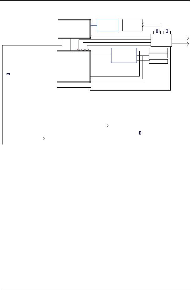
System Block Diagram
|
|
|
|
|
|
|
|
|
|
|
|
|
|
|
|
DDR3SODIMM1 |
|
DDR3 channel A |
|||||
|
|
|
|
|
|
|
|
|
|
|
|
|
|
|
|
|
|
|
|
|
|||
|
|
|
|
DDR3SODIMM2 |
|
DDR3 channel B |
|||||
|
|
|
|
|
|
|
|
|
|
|
|
|
|
|
|
|
|
|
|
|
|
|
|
|
|
|
|
|
CPU SideBand TemperatureSense I2C |
||||||
|
|
|
|
|
|
|
|
|
|
|
|
|
|
|
|
|
|
|
|
|
PCI-Expresss |
|
|
|
|
|
|
P0 |
|
|
|
|
P2 |
|
|
|
|
|
|
|
|
|
|
|
|
|
|
|
|
|
LAN |
|
|
Mini PCI-E |
|
|
|||
|
|
|
BROADCOM |
|
|
Card |
|
|
|
||
|
|
|
PCIE-LAN |
|
|
|
|
|
|
|
|
|
|
|
BCM57780 |
|
|
(Wireless LAN) |
|
|
|||
|
|
|
|
|
|
|
|||||
|
|
|
(10/100/1000) |
|
|
|
|
|
|
|
|
|
|
|
|
|
|
|
|
|
|
|
|
25MHz |
|
|
|
|
|
|
|
|
|
||
|
|
|
RJ45 |
|
|
SATA0 150MB |
|
||||
|
|
|
|
|
|
||||||
|
|
|
|
|
|
|
|||||
|
|
|
|
|
|
|
|
||||
|
|
|
|
|
|
|
|||||
|
|
|
SATA - HDD |
|
|
|
|||||
|
|
|
|
|
|
|
3 Gb/s |
|
|
|
|
|
|
|
|
|
|
SATA1 150MB |
|
||||
|
|
|
|
|
|
|
|
||||
|
|
|
SATA - ODD |
|
|
|
|||||
|
|
|
|
|
|
|
3 Gb/s |
|
|
|
|
|
|
|
|
|
|
|
|
|
|
|
No PCI I/F |
|
|
|
|
|
|
|
|
|
|
|
|
|
|
|
|
|
|
|
|
|
|
|
|
AMD Champlain |
CPU THERMAL |
PWM FAN SCH. |
CPU (PROCHOT) |
|
||
S1G4 Processor |
SENSOR |
|
|
E.C. (CPUFAN#) |
|
|
(Reserve Only) |
|
|
|
25MHz |
32.768KHz |
|
35mm X 35mm |
|
|
|
|
|
|
638P (PGA) 35W |
CPU_CLK |
|
|
|
From SB |
|
|
|
|
|
|||
|
NBGFX_CLK |
|
|
|
||
|
NBGPP_CLK |
|
|
|
CLK GEN |
|
|
|
|
|
SB820M |
||
|
SBLINK_CLK |
|
|
|
||
HT3 |
|
|
|
|
|
|
|
|
|
|
|
|
|
1.8GHz |
|
ATI |
EXT HDMI |
HDMI |
|
|
|
|
|
||||
|
PCI-Express 16X |
Park XT |
EXT CRT |
|
|
|
NORTH BRIDGE |
128-bit M2 Pkg |
CRT |
|
|||
|
|
|
||||
29mm X 29mm |
EXT LVDS |
|
|
|||
RS880M GFX Engine: 500MHz |
|
|
LVDS |
|
||
|
|
|
|
|
||
A11 |
|
|
|||
VRAM DDR3 |
|||||
|
|
|
64MX16X4,64 bit |
||
21mm X 21mm, 528pin BGA |
800MHz |
||||
TDP: 13W |
INT HDMI |
||||
INT CRT |
|||||
0.95 ~ 1.1V |
|||||
|
|
|
INT LVDS |
||
A-LINK |
|
|
|
|
|
|
|
|
|
|
|
CLK_PCI_775
PCLK_DEBUG
SOUTH BRIDGE |
|
|
|
|
|
|
|
|
|
|
|
|
|
|
|
|
|
|
|
|
|
|
|
SB820M |
|
|
|
|
|
|
|
|
|
|
|
|
|
|
|
|
|
|
|
|
|
|
|
A12 |
|
|
|
P0 |
|
|
|
|
|
|
P9 |
|
|
|
|
P13 |
|
|
FFC |
|
|||
|
|
|
|
|
|
|
|
|
|
|
|
|
|
|
|
|
|
|
|
|
|
||
|
|
USB2.0 Port |
|
|
|
Blue Tooth |
|
|
|
Web-Camera |
|
|
|
|
|||||||||
|
|
|
|
|
|
|
|
|
|
|
|
|
|||||||||||
23mm X 23mm, 605pin BGA |
|
|
on board x1 |
|
|
|
|
|
|
|
|
|
|
|
|
|
|
|
|
|
|
||
|
|
|
|
|
|
|
|
|
|
|
|
|
|
|
|
|
|
|
|
|
USB BOARD |
||
|
|
|
|
|
|
|
|
P4 |
|
|
|
|
|
P10 |
|
|
|
|
|
|
|
||
|
|
|
|
|
|
|
|
|
|
|
|
|
|
|
|
USB2.0 Ports x3 |
|||||||
|
|
|
|
|
|
Mini Card |
|
|
|
CardReader |
|
|
|
|
|
||||||||
|
|
|
|
|
|
|
|
|
|
|
|
||||||||||||
TDP: 4.9W |
|
|
PCLK_DEBUG |
|
WLAN & Debug |
|
|
AU6347 |
|
|
|
|
|
|
|
||||||||
|
|
|
|
|
|
|
|
|
|
|
|
|
|
|
|
|
|
|
|
|
|||
|
|
|
|
|
|
|
|
|
|
|
|
|
|
|
|
|
|
|
|
|
|
|
|
|
|
|
|
|
|
|
|
|
|
|
|
|
|
|
|
|
|
|
|
|
|
|
|
|
|
|
|
|
|
|
|
|
|
|
|
|
|
|
|
|
|
|
|
|
|
|
|
|
|
|
|
|
|
|
|
|
|
|
|
|
|
|
|
|
|
|
|
|
|
|
|
|
|
|
CLK_PCI_775 |
|
|
|
|
|
LPC |
|
|
Azalia |
|
12MHz |
|
||||||||||||
|
|
|
|
|
|
|
|
|
|
||||||||||||||||
|
|
|
|
|
|
|
|
|
|
|
|
|
|
|
|
|
|
|
|
|
|
|
|||
|
|
Winbond KBC |
|
|
|
Audio CODEC |
|
|
|
|
|
|
|
|
|||||||||||
|
|
|
|
|
|
|
|
|
|
|
|
|
|
|
|||||||||||
CPU SideBand TemperatureSense I2C |
|
NPCE781L |
|
|
RTL ALC272X |
|
|
|
|
|
|||||||||||||||
|
|
|
|
|
|
|
|
|
|
|
|
|
|
|
|
|
|
|
|
|
|
|
|||
|
|
|
|
|
|
|
|
|
|
|
|
|
|
|
|
|
|
|
|
|
|
|
|
|
|
|
|
|
|
|
|
|
|
|
|
|
|
|
|
|
|
|
|
|
|
|
|
|
|
|
|
|
|
|
|
|
|
|
|
|
|
|
|
|
|
|
|
|
|
|
|
|
|
|
|
|
|
|
|
|
|
|
|
|
|
|
|
|
|
|
|
|
|
|
|
|
|
|
|
|
|
|
|
|
|
Keyboard |
|
|
SPI ROM |
|
Digital MIC |
|
|
|
AUDIO CONN |
|
Speaker CN |
|
|
|
|
||||||||
|
|
TouchPad |
|
|
|
|
|
|
|
|
|
|
|
(H.P./ MIC) |
|
|
|
|
|
|
|
||||
|
|
|
|
|
|
|
|
|
|
|
|
|
|
|
|
|
|
|
|
|
|
|
|
|
|
6 |
Chapter 1 |
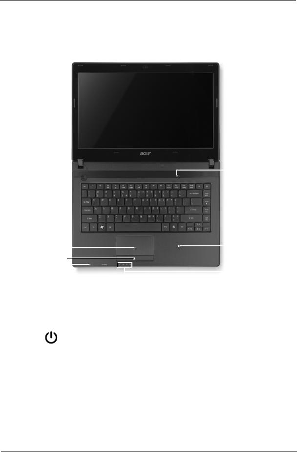
Your Acer Notebook tour
Top View
1
2 
10
3
4
|
|
|
5 |
|
9 |
|
|
|
6 |
|
|
|
|
|
7 |
|
8 |
|
|
|
|
|
|
|
|
|
|
|
|
# |
|
Icon |
|
Item |
Description |
|
|
|
|
|
|
|
1 |
|
|
Acer Crystal Eye |
Web camera for video communication. (only for certain |
|
|
|
|
webcam |
models) |
|
|
|
|
|
|
|
2 |
|
|
Display screen |
Also called Liquid-Crystal Display (LCD), displays computer |
|
|
|
|
|
output (configuration may vary by model). |
|
|
|
|
|
|
|
3 |
|
|
Power button |
Turns the computer on and off. |
|
|
|
|
|
|
|
4 |
|
|
Keyboard |
For entering data into your computer |
|
|
|
|
|
|
|
5 |
|
|
Touchpad |
Touch-sensitive pointing device which functions like a |
|
|
|
|
|
computer mouse. |
|
|
|
|
|
|
|
6 |
|
|
Click buttons |
The left and right buttons function like the left and right |
|
|
|
|
(left, and right) |
mouse buttons. |
|
|
|
|
|
|
|
7 |
|
|
Microphone |
Internal microphone for sound recording. |
|
|
|
|
|
|
Chapter 1 |
7 |
# |
|
Icon |
Item |
Description |
|
|
|
|
|
|
8 |
|
Power indicator |
Indicates the computer's power status. |
|
|
|
|
|
|
|
|
Battery indicator |
Indicates the computer's battery status. |
|
|
|
|
1. Charging: The light shows amber when the battery is |
|
|
|
|
charging. |
|
|
|
|
2. Fully charged: The light shows blue when in AC mode. |
|
|
|
|
|
|
|
|
HDD indicator |
Indicates when the hard disk drive is active. |
|
|
|
|
|
|
|
|
Communication |
Indicates the computer’s wireless connectivity device status. |
|
|
|
indicator |
|
|
|
|
|
|
|
9 |
|
Palmrest |
Comfortable support area for your hands when you use the |
|
|
|
|
computer. |
|
|
|
|
|
|
10 |
|
Speaker |
Delivers audio output. |
|
|
|
|
|
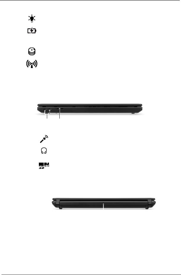
Closed Front View
|
1 |
2 |
|
|
|
|
|
No. |
Icon |
Item |
Description |
|
|
|
|
1 |
|
Microphone jack |
Accepts inputs from external microphones. |
|
|
|
|
|
|
Headphone/ |
Connects to audio line-out devices (e.g., |
|
|
speaker/line-out |
speakers, headphones). |
|
|
jack |
|
|
|
|
|
2 |
|
2-in-1 card reader |
Accepts Secure Digital (SD), MultiMediaCard |
|
|
|
(MMC). |
|
|
|
Note: Push to remove/install the card. Only one |
|
|
|
card can operate at any given time. |
|
|
|
|
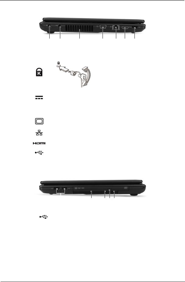
Rear view
|
|
|
1 |
|
|
|
|
No. |
Icon |
Item |
Description |
|
|
|
|
1 |
|
Battery bay |
Houses the computer's battery pack. |
|
|
|
|
8 |
Chapter 1 |
Left View
|
1 |
2 |
3 |
4 |
5 |
6 |
7 |
|
|
|
|
|
|
|
|
No. |
Icon |
Item |
|
|
|
|
Description |
|
|
|
|
||||
1 |
|
Kensington lock slot |
Connects to a Kensington-compatible computer |
||||
|
|
|
|
security lock. |
|
|
|
|
|
|
|
Note: Wrap the computer security lock cable |
|||
|
|
|
|
around an immovable object such as a table or |
|||
|
|
|
|
handle of a locked drawer. Insert the lock into the |
|||
|
|
|
|
notch and turn the key to secure the lock. Some |
|||
|
|
|
|
keyless models are also available. |
|||
|
|
|
|
|
|||
2 |
|
DC-in jack |
|
Connects to an AC adapter. |
|||
|
|
|
|
||||
3 |
|
Ventilation slots |
Enable the computer to stay cool, |
||||
|
|
|
|
even after prolonged use. |
|||
|
|
|
|
||||
4 |
|
External display |
Connects to a display device (e.g., external |
||||
|
|
(VGA) port |
|
monitor, LCD projector). |
|||
|
|
|
|
||||
5 |
|
Ethernet (RJ-45) port |
Connects to an Ethernet 10/100/1000-based |
||||
|
|
|
|
network. |
|
|
|
|
|
|
|
|
|||
6 |
|
HDMI port |
|
Supports high-definition digital video |
|||
|
|
|
|
connections. |
|
|
|
|
|
|
|
|
|||
7 |
|
USB 2.0 port |
|
Connects to USB 2.0 devices (e.g., USB mouse, |
|||
|
|
|
|
USB camera). |
|
|
|
|
|
|
|
|
|
|
|
Right View
|
1 |
2 |
3 4 5 |
|
|
|
|
|
|
No. |
Icon |
|
Item |
Description |
|
|
|
|
|
1 |
|
USB 2.0 ports |
Connect to USB 2.0 devices |
|
|
|
|
|
(e.g., USB mouse, USB camera). |
|
|
|
|
|
2 |
|
Optical drivez |
Internal optical drive; accepts CDs or |
|
|
|
|
|
DVDs. |
|
|
|
|
|
3 |
|
Optical disk access |
Lights up when the optical drive is |
|
|
|
indicator |
|
active. |
|
|
|
|
|
4 |
|
Optical drive eject |
Ejects the optical disk from the drive . |
|
|
|
button |
|
|
|
|
|
|
|
Chapter 1 |
9 |
No. |
Icon |
Item |
Description |
|
|
|
|
5 |
|
Emergency eject |
Ejects the optical drive tray when the |
|
|
hole |
computer is turned off. |
|
|
|
Note: Insert a paper clip to the |
|
|
|
emergency eject hole to eject the |
|
|
|
optical drive tray when the computer |
|
|
|
is off. |
|
|
|
|
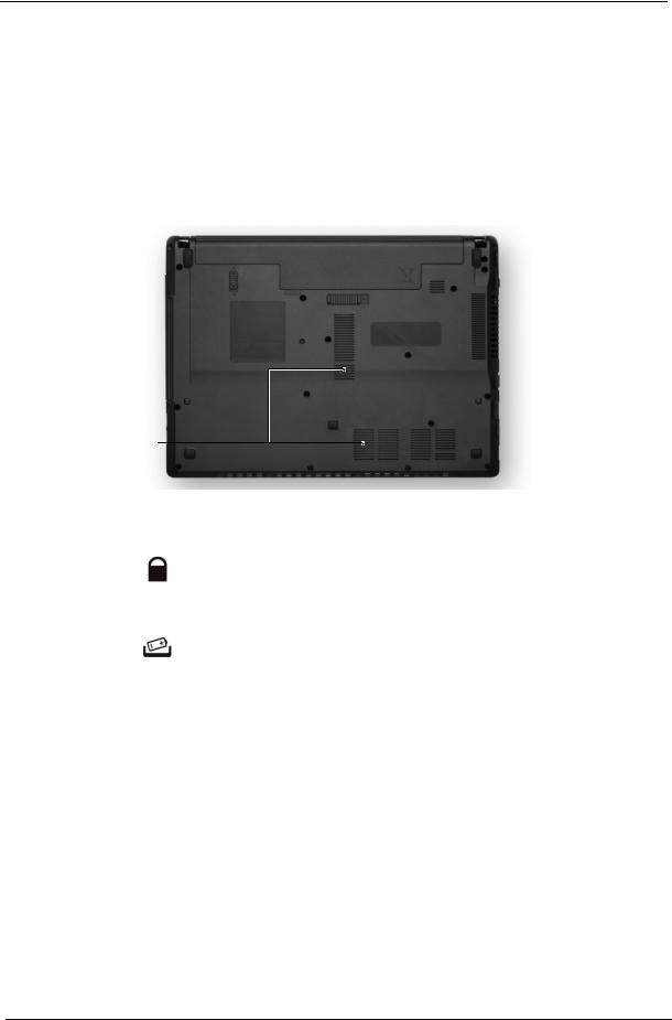
Base View
1 
2
 4
4
3
No. |
Icon |
Item |
Description |
|
|
|
|
1 |
|
Battery bay |
Houses the computer's battery pack. |
2 |
|
Battery lock |
Locks the battery in position. |
|
|
|
|
3 |
|
Ventilation slots |
Enable the computer to stay cool, even after |
|
|
|
prolonged use. |
|
|
|
|
4 |
|
Battery release |
Releases the battery for removal. |
|
|
latch |
|
|
|
|
|
10 |
Chapter 1 |
Indicators
The computer has several easy-to-read status indicators.
Icon |
Function |
Description |
|
|
|
|
Power |
Indicates the computer's power status. |
|
|
|
|
Battery |
Indicates the computer's battery status. |
|
|
NOTE: 1. Charging: The light shows amber when |
|
|
the battery is charging. 2. Fully charged: The light |
|
|
shows green when in AC mode. |
|
|
|
|
HDD |
Indicates when the hard disk drive is active. |
|
|
|
|
Communication indicator |
Indicates the computer’s wireless connectivity |
|
|
device status. |
|
|
|
Chapter 1 |
11 |
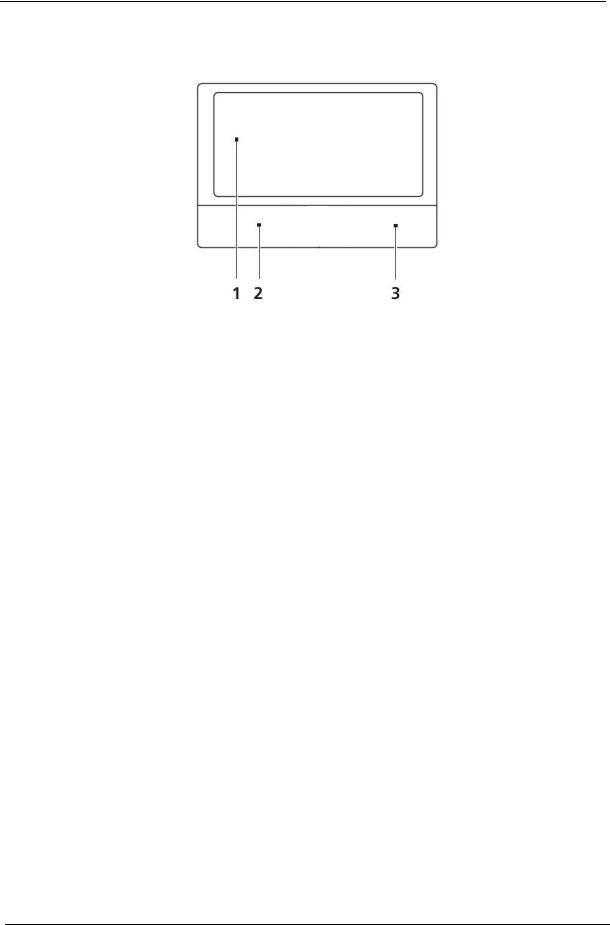
Touchpad Basics
The following items show you how to use the Touchpad:
•Move your finger across the Touchpad (1) to move the cursor.
•Press the left (2) and right (3) buttons located beneath the Touchpad to perform selection and execution functions. These two buttons are similar to the left and right buttons on a mouse. Tapping on the Touchpad is the same as clicking the left button.
Function |
Left Button (2) |
Right Button (3) |
Main Touchpad (1) |
|
|
|
|
Execute |
Quickly click twice. |
|
Tap twice (at the same speed |
|
|
|
as double-clicking a mouse |
|
|
|
button). |
|
|
|
|
Select |
Click once. |
|
Tap once. |
|
|
|
|
Drag |
Click and hold, then use |
|
Tap twice (at the same speed |
|
finger on the Touchpad to |
|
as double-clicking a mouse |
|
drag the cursor. |
|
button); rest your finger on |
|
|
|
the Touchpad on the second |
|
|
|
tap and drag the cursor. |
|
|
|
|
Access |
|
Click once. |
|
context menu |
|
|
|
|
|
|
|
NOTE: When using the Touchpad, keep it - and your fingers - dry and clean. The Touchpad is sensitive to finger movement; hence, the lighter the touch, the better the response. Tapping too hard will not increase the Touchpad’s responsiveness.
12 |
Chapter 1 |

Using the Keyboard
The keyboard has full-sized keys and an embedded numeric keypad, separate cursor, lock, Windows, function and special keys.
Lock Keys and embedded numeric keypad
The keyboard has two lock keys which you can toggle on and off.
Lock key |
Description |
|
|
Caps Lock |
When Caps Lock is on, all alphabetic characters typed are in uppercase. |
|
|
Num Lock |
When Num Lock is on, the embedded keypad is in numeric mode. |
<Fn> + <F11> |
|
|
|
Scroll Lock |
When Scroll Lock is on, the screen moves one line up or down when you press |
<Fn> + <F12> |
the up or down arrow keys respectively. Scroll Lock does not work with some |
|
applications. |
|
|
Chapter 1 |
13 |
Windows Keys
The keyboard has two keys that perform Windows-specific functions.
Key |
Description |
|
|
Windows key |
Pressed alone, this key has the same effect as clicking on the Windows Start button; |
|
it launches the Start menu. It can also be used with other keys to provide a variety of |
|
functions: |
|
< >: Open or close the Start menu |
|
< > + <D>: Display the desktop |
|
< > + <E>: Open Windows Explore |
|
< > + <F>: Search for a file or folder |
|
< > + <G>: Cycle through Sidebar gadgets |
|
< > + <L>: Lock your computer (if you are connected to a network domain), or |
|
switch users (if you're not connected to a network domain) |
|
< > + <M>: Minimizes all windows |
|
< > + <R>: Open the Run dialog box |
|
< > + <T>: Cycle through programs on the taskbar |
|
< > + <U>: Open Ease of Access Center |
|
< > + <X>: Open Windows Mobility Center |
|
< > + <BREAK>: Display the System Properties dialog box |
|
< > + <SHIFT+M>: Restore minimized windows to the desktop |
|
< > + <TAB>: Cycle through programs on the taskbar |
|
< > + <SPACEBAR>: Bring all gadgets to the front and select Windows Sidebar |
|
<CTRL> + < > + <F>: Search for computers (if you are on a network) |
|
<CTRL> + < > + <TAB>: Use the arrow keys to cycle through programs on the |
|
taskbar |
Note: Depending on your edition of Windows, some shortcuts may not function as described.
14 |
Chapter 1 |

Hot Keys
The computer employs hotkeys or key combinations to access most of the computer’s controls like screen brightness, volume output and the BIOS utility.
To activate hot keys, press and hold the <Fn> key before pressing the other key in the hotkey combination.
Hotkey |
Icon |
Function |
Description |
|
|
|
|
<Fn> + <F3> |
|
Communication key |
Enables / disables the computer's |
|
|
|
communication devices. (Communication |
|
|
|
devices may vary by configuration.) |
|
|
|
|
<Fn> + <F4> |
|
Sleep |
Puts the computer in Sleep mode. |
|
|
|
|
<Fn> + <F5> |
|
Display toggle |
Switches display output between the display |
|
|
|
screen, external monitor (if connected) and |
|
|
|
both. |
|
|
|
|
<Fn> + <F6> |
|
Display Off |
Turns the display screen backlight off to save |
|
|
|
power. Press any key to return. |
<Fn> + <F7> |
|
Touchpad toggle |
Turns the internal Touchpad on and off. |
|
|
|
|
<Fn> + <F8> |
|
Speaker toggle |
Turns the speakers on and off. |
|
|
|
|
<Fn> + <Z> |
|
Brightness up |
Increases the screen brightness. |
|
|
|
|
<Fn> + <Y> |
|
Brightness down |
Decreases the screen brightness. |
|
|
|
|
<Fn> + <U> |
|
Volume up |
Increases the sound volume. |
|
|
|
|
<Fn> + <V> |
|
Volume down |
Decreases the sound volume. |
|
|
|
|
<Fn> + <Home> |
|
Play/Pause |
Play or pause a selected media file. |
|
|
|
|
<Fn> +<Pg Up> |
|
Stop |
Stop playing the selected media file. |
|
|
|
|
<Fn> +<Pg Dn> |
|
Previous |
Return to the previous media file. |
|
|
|
|
<Fn> + <End> |
|
Next |
Jump to the next media file. |
|
|
|
|
Chapter 1 |
15 |

Hardware Specifications and Configurations
Processor
Item |
|
|
|
|
|
|
Specification |
|
|
|
|
|
|
|
|
|
|
|
|
|
|
|
|
CPU |
|
|
AMD Family 10h Champlain Processor S1g4 Package |
|
|
|
|||||
|
|
|
|
|
|
|
|
|
|
|
|
Type |
|
|
35W CPU |
|
|
|
|
|
|
|
|
|
|
|
|
|
|
|
|
|
|
|
|
CPU Package |
|
528-FCBGA package, 21mmx21mm - S1g3 |
|
|
|
|
|||||
|
|
|
|
|
|
|
|
|
|
|
|
Power |
|
|
1.1V |
|
|
|
|
|
|
|
|
|
|
|
|
|
|
|
|
|
|
|
|
On-die Cache |
|
1MB L2 cache |
|
|
|
|
|
|
|||
|
|
|
|
|
|
|
|
|
|
|
|
Front Side Bus |
|
667/800/1066 MHz |
|
|
|
|
|
|
|||
|
|
|
|
|
|
|
|
|
|
|
|
Processor Specifications (Aspire 4552/5442G) |
|
|
|
|
|
||||||
|
|
|
|
|
|
|
|
|
|
|
|
Item |
CPU |
|
Cores |
Bus |
Mfg |
Cache |
Package |
Core |
Acer P/N |
|
|
Speed |
|
|
|||||||||
|
Speed |
Tech |
Size |
Voltage |
|
||||||
|
(Ghz) |
|
|
|
|
|
|||||
|
|
|
|
|
|
|
|
|
|
||
|
|
|
|
|
|
|
|
|
|
|
|
AAP320 |
2.1 |
|
|
2 |
3600 |
45 nm |
1M |
638-pin |
25W |
KC.AP002.320 |
|
|
|
|
|
|
MHz |
|
|
micro- |
|
|
|
|
|
|
|
|
|
|
|
PGA |
|
|
|
|
|
|
|
|
|
|
|
|
|
|
|
APN830 |
2.1 |
|
|
3 |
3600 |
45 nm |
1.5M |
638-pin |
35W |
KC.PN002.830 |
|
|
|
|
|
|
MHz |
|
|
micro- |
|
|
|
|
|
|
|
|
|
|
|
PGA |
|
|
|
|
|
|
|
|
|
|
|
|
|
|
|
APN930 |
2.0 |
|
|
4 |
3600 |
45 nm |
2M |
638-pin |
35W |
KC.PN002.930 |
|
|
|
|
|
|
MHz |
|
|
micro- |
|
|
|
|
|
|
|
|
|
|
|
PGA |
|
|
|
|
|
|
|
|
|
|
|
|
|
|
|
AAN350 |
2.4 |
|
|
2 |
3200 |
45 nm |
1M |
638-pin |
35W |
KC.AN002.350 |
|
|
|
|
|
|
MHz |
|
|
micro- |
|
|
|
|
|
|
|
|
|
|
|
PGA |
|
|
|
|
|
|
|
|
|
|
|
|
|
|
|
AAP340 |
2.2 |
|
|
2 |
3200 |
45 nm |
1M |
638-pin |
25W |
KC.AP002.340 |
|
|
|
|
|
|
MHz |
|
|
micro- |
|
|
|
|
|
|
|
|
|
|
|
PGA |
|
|
|
|
|
|
|
|
|
|
|
|
|
|
|
APN850 |
2.2 |
|
|
3 |
3600 |
45 nm |
1.5M |
638-pin |
35W |
KC.PN002.850 |
|
|
|
|
|
|
MHz |
|
|
micro- |
|
|
|
|
|
|
|
|
|
|
|
PGA |
|
|
|
|
|
|
|
|
|
|
|
|
|
|
|
APN950 |
2.1 |
|
|
4 |
3600 |
45 nm |
2M |
638-pin |
35W |
KC.PN002.950 |
|
|
|
|
|
|
MHz |
|
|
micro- |
|
|
|
|
|
|
|
|
|
|
|
PGA |
|
|
|
|
|
|
|
|
|
|
|
|
|
|
|
APP840 |
1.9 |
|
|
3 |
3600 |
45 nm |
1.5M |
638-pin |
25W |
KC.PP002.840 |
|
|
|
|
|
|
MHz |
|
|
micro- |
|
|
|
|
|
|
|
|
|
|
|
PGA |
|
|
|
|
|
|
|
|
|
|
|
|
|
|
|
APP940 |
1.7 |
|
|
4 |
3600 |
45 nm |
2M |
638-pin |
25W |
KC.PP002.940 |
|
|
|
|
|
|
MHz |
|
|
micro- |
|
|
|
|
|
|
|
|
|
|
|
PGA |
|
|
|
|
|
|
|
|
|
|
|
|
|
|
|
ATP540 |
2.4 |
|
|
2 |
3600 |
45 nm |
2M |
638-pin |
25W |
KC.TP002.540 |
|
|
|
|
|
|
MHz |
|
|
micro- |
|
|
|
|
|
|
|
|
|
|
|
PGA |
|
|
|
|
|
|
|
|
|
|
|
|
|
||
Processor Specifications (Aspire 4252) |
|
|
|
|
|
|
|||||
|
|
|
|
|
|
|
|
|
|
|
|
Item |
CPU |
|
Cores |
Bus |
Mfg |
Cache |
Package |
Core |
Acer P/N |
|
|
Speed |
|
|
|||||||||
|
Speed |
Tech |
Size |
Voltage |
|
||||||
|
(Ghz) |
|
|
|
|
|
|||||
|
|
|
|
|
|
|
|
|
|
||
|
|
|
|
|
|
|
|
|
|
|
|
AMD |
2.3 |
|
|
1 |
3200 |
45 nm |
512K |
638-pin |
25W |
KC.V0002.140 |
|
V140 |
|
|
|
|
MHz |
|
|
micro- |
|
|
|
|
|
|
|
|
|
|
|
PGA |
|
|
|
|
|
|
|
|
|
|
|
|
|
|
|
16 |
Chapter 1 |

North Bridge Chipset
Item |
|
|
Specification |
|
|
|
|
Chipset |
|
RS880M |
|
Package |
|
• Single chip solution in 55nm, 1.1V low power CMOS technology. |
|
|
|
• |
528-FCBGA package, 21mmx21mm. |
|
|
|
|
Features |
|
• |
CPU HyperTransport™ Interface |
|
|
• Caspian-series processors. |
|
|
|
• |
ATI HyperMemory |
|
|
• |
PCI ExpressR Interface |
|
|
• A-Link Express II Interface |
|
|
|
• Northbridge-Southbridge messaging functionalities |
|
|
|
• |
2D Acceleration |
|
|
• |
3D Acceleration |
|
|
• |
Motion Video Acceleration |
|
|
• |
Multiple Display |
|
|
• |
System Clocks |
|
|
• PC Design Guide Compliance |
|
|
|
|
|
Southbridge Chipset |
|
|
|
|
|
|
|
Item |
|
|
Feature |
|
|
|
|
Chipset |
SB820M |
|
|
|
|
||
Package |
SB820M 23 mm x 23 mm x 0.8 mm Pitch 605-FCBGA |
||
|
|
|
|
Features |
• |
Processor Interface |
|
|
• A-Link Express II interface to Northbridges |
||
|
• |
PCI ExpressR Controller |
|
|
• PCI Host Bus Controller |
||
|
• |
USB Controllers |
|
|
• Supports port disable with individual control |
||
|
• |
SMBus Controller |
|
|
• |
Interrupt Controller |
|
|
• |
DMA Controller |
|
|
• LPC host bus Controller |
||
|
• |
SATA Controller |
|
|
• |
IDE emulation mode |
|
|
• |
AMD RAID Support |
|
|
• |
AHCI Support |
|
|
• |
High Definition Audio |
|
|
• Supports up to 4 codecs |
||
|
• Gigabit Ethernet Media Access |
||
|
• |
Controller (GbE MAC) |
|
|
• |
Timers |
|
|
• Real Time Clock (RTC) |
||
|
• |
Power Management |
|
|
• |
Consumer IR |
|
|
• |
Hardware Monitoring |
|
|
• |
Integrated Clock Function |
|
|
|
|
|
Chapter 1 |
17 |

CPU Fan True Value Table (CPU)
Fan On (Celsius) |
|
Fan Off (Celsius) |
|
RPM |
|
|
|
|
|
|
|
|
|
45 |
42 |
|
|
2350 |
|
|
50 |
48 |
|
|
2800 |
|
|
|
|
|
|
|
|
|
58 |
56 |
|
|
3100 |
|
|
|
|
|
|
|
|
|
63 |
61 |
|
|
3500 |
|
|
|
|
|
|
|
|
|
82 |
80 |
|
|
3850 |
|
|
|
|
|
|
|
|
|
92 |
85 |
|
|
max (5V) |
|
|
|
|
|
|
|
|
|
Throttling 50%: On= 95°C; OFF=90°C |
|
|
||||
OS shut down at 105°C; H/W shut down at 105°C |
|
|
||||
CPU Fan True Value Table (GPU) |
|
|
||||
|
|
|
|
|
|
|
Fan On (Celsius) |
|
Fan Off (Celsius) |
|
RPM |
|
|
|
|
|
|
|
|
|
45 |
42 |
|
|
2350 |
|
|
50 |
48 |
|
|
2800 |
|
|
|
|
|
|
|
|
|
58 |
56 |
|
|
3100 |
|
|
|
|
|
|
|
|
|
63 |
61 |
|
|
3500 |
|
|
|
|
|
|
|
|
|
82 |
80 |
|
|
3850 |
|
|
|
|
|
|
|
|
|
92 |
85 |
|
|
max (5V) |
|
|
|
|
|
|
|
|
|
Throttling 50%: On= 85°C; OFF=80°C |
|
|
||||
OS shut down at 90°C; H/W shut down at 90°C |
|
|
||||
System Memory |
|
|
|
|
|
|
|
|
|
|
|
|
|
Item |
|
|
|
Specification |
||
|
|
|
|
|
|
|
Memory controller |
|
|
RS880M |
|
|
|
Memory size |
|
|
0MB (no on-board memory) |
|
|
|
|
|
|
|
|
|
|
DIMM socket number |
|
|
2 sockets |
|
|
|
|
|
|
|
|||
Supports memory size per socket |
8 GB |
|
|
|||
|
|
|
|
|
||
Supports maximum memory size |
|
8GB maximum per one DIMM |
|
|
||
|
|
|
|
|||
Supports DIMM type |
|
|
JEDEC 204-pin DDR3-800/1066 SODIMM for PC3-10600/ PC3- |
|||
|
|
|
8500/ PC3-6400 |
|
|
|
|
|
|
|
|
|
|
Supports DIMM speed |
|
|
1.87ns @ CL = 7 (DDR3-1066) |
|
|
|
|
|
|
1.87ns @ CL = 8 (DDR3-1066) |
|
|
|
|
|
|
2.5ns @ CL = 5 (DDR3-800) |
|
|
|
|
|
|
2.5ns @ CL = 6 (DDR3-800) |
|
|
|
|
|
|
|
|
|
|
Supports DIMM voltage |
|
|
1.5V +/- 0.075V |
|
|
|
|
|
|
|
|||
Supports DIMM package |
|
|
204-pin SODIMM, 67.75”x 30.15”x 3.8”(Max) |
|||
|
|
|
||||
Memory module combinations |
|
You can install memory modules in any combinations as long as |
||||
|
|
|
they match the above specifications. |
|||
|
|
|
|
|
|
|
18 |
Chapter 1 |

System Board Major Chips
Item |
|
Specification |
||
|
|
|
|
|
Northbridge |
|
RS880M |
||
Southbridge |
|
SB820M |
||
|
|
|
|
|
VGA |
|
AMD Park XT |
||
|
|
|
|
|
LAN |
|
BCM57780 |
||
|
|
|
|
|
USB 2.0 |
|
SB820M |
||
|
|
|
|
|
Super I/O controller |
|
SB820M |
||
|
|
|
|
|
Bluetooth |
|
SB820M |
||
|
|
|
|
|
Wireless |
|
SB820M |
||
|
|
|
|
|
PCMCIA |
|
N/A |
||
|
|
|
|
|
Audio codec |
|
ALC271 |
||
|
|
|
|
|
Card reader |
|
AU6437 |
||
|
|
|
|
|
BIOS |
|
|
|
|
|
|
|
|
|
Item |
|
|
Specification |
|
|
|
|
|
|
BIOS vendor |
|
Phoenix |
|
|
|
|
|
|
|
BIOS Version |
|
v4.0 |
|
|
|
|
|
|
|
BIOS ROM type |
|
W25X16A |
|
|
|
|
|
|
|
BIOS ROM size |
|
4MB |
|
|
|
|
|
|
|
Features |
|
• |
Flash ROM 4MB |
|
|
|
• |
Support ISIPP |
|
|
|
• |
Support Acer UI |
|
|
|
• Support multi-boot |
|
|
|
|
• Suspend to RAM (S3)/Disk (S4) |
|
|
|
|
• Various hot-keys for system control |
|
|
|
|
• Support SMBIOS 2.3, PCI2.2. |
|
|
|
|
• Refer to Acer BIOS specification. |
|
|
|
|
• DMI utility for BIOS serial number configurable/asset tag |
|
|
|
|
• |
Support PXE |
|
|
|
• |
Support Y2K solution |
|
|
|
• |
Support WinFlash |
|
|
|
• Wake on LAN from S3 |
|
|
|
|
• Wake on LAN form S4 in AC mode |
|
|
|
|
• |
System information |
|
|
|
|
|
|
Chapter 1 |
19 |

Memory Combinations
Slot 1 |
|
|
|
|
Slot 2 |
|
Total Memory |
|
|
|
|
|
|
|
|
|
|
|
|
0MB |
|
1024MB |
|
|
1024MB |
|
|
||
0MB |
|
2048MB |
|
|
2048MB |
|
|
||
|
|
|
|
|
|
|
|
|
|
0MB |
|
4096MB |
|
|
4096MB |
|
|
||
|
|
|
|
|
|
|
|
|
|
1024MB |
|
0MB |
|
|
1024MB |
|
|
||
|
|
|
|
|
|
|
|
|
|
1024MB |
|
512MB |
|
|
1536MB |
|
|
||
|
|
|
|
|
|
|
|
|
|
1024MB |
|
1024MB |
|
|
2048MB |
|
|
||
|
|
|
|
|
|
|
|
|
|
1024MB |
|
2048MB |
|
|
3072MB |
|
|
||
|
|
|
|
|
|
|
|
|
|
2048MB |
|
0MB |
|
|
2048MB |
|
|
||
|
|
|
|
|
|
|
|
|
|
2048MB |
|
512MB |
|
|
2560MB |
|
|
||
|
|
|
|
|
|
|
|
|
|
2048MB |
|
1024MB |
|
|
3072MB |
|
|
||
|
|
|
|
|
|
|
|
|
|
2048MB |
|
2048MB |
|
|
4096MB |
|
|
||
|
|
|
|
|
|
|
|
|
|
2048MB |
|
4096MB |
|
|
6144MB |
|
|
||
|
|
|
|
|
|
|
|
|
|
4096MB |
|
4096MB |
|
|
8192MB |
|
|
||
|
|
|
|
|
|
|
|
|
|
Wireless Module 802.11b/g/Draft-N |
|
|
|
|
|
||||
|
|
|
|
|
|
|
|
|
|
Item |
|
|
|
|
Specification |
|
|
||
|
|
|
|
|
|
|
|
||
Manufacturer |
Foxconn |
|
|
|
Liteon |
|
|||
|
|
|
|
|
|
|
|
|
|
Model |
43225 |
|
|
|
HB95 |
HB97 |
HB97 |
|
|
|
|
|
|
|
|
|
|
||
Supported Standards |
IEEE 802.11b/g/n |
|
IEEE 802.11b/g |
IEEE 802.11b/11g |
IEEE 802.11b/g/n |
|
|||
|
|
|
|
|
|
|
|
|
|
LAN Interface |
|
|
|
|
|
|
|
|
|
|
|
|
|
|
|
|
|
|
|
Item |
|
|
|
|
|
Specification |
|
|
|
|
|
|
|
|
|
|
|
|
|
Part Name |
|
|
|
|
BCM57780 |
|
|
|
|
|
|
|
|
|
|
|
|
|
|
Package |
|
|
|
|
64pin QFN |
|
|
|
|
|
|
|
|
|
|
|
|
||
Features |
|
|
|
|
Supports 10/100/1000 Mb/s |
|
|
||
|
|
|
|
|
|
|
|
|
|
Interface |
|
|
|
|
PCI-Express |
|
|
|
|
|
|
|
|
|
|
|
|||
3G Module (Not available with this model) |
|
|
|
|
|
||||
|
|
|
|
|
|
|
|
|
|
Item |
|
|
|
|
|
Specification |
|
|
|
|
|
|
|
|
|
|
|
|
|
Manufacturer |
|
|
|
|
|
|
|
|
|
Model |
|
|
|
|
|
|
|
|
|
|
|
|
|
|
|
|
|
|
|
Card Type |
|
|
|
|
|
|
|
|
|
|
|
|
|
|
|
|
|
|
|
Throughput |
|
|
|
|
|
|
|
|
|
|
|
|
|
|
|
|
|
|
|
Supported Services |
|
|
|
|
|
|
|
|
|
|
|
|
|
|
|
|
|
|
|
Speaker |
|
|
|
|
|
|
|
|
|
|
|
|
|
|
|
|
|
|
|
Item |
|
|
|
|
|
Specification |
|
|
|
|
|
|
|
|
|
|
|
||
Vendor |
|
|
|
|
Vansonic Enterprise Co., Ltd. |
|
|
||
|
|
|
|
|
|
|
|
|
|
Module No. |
|
|
|
|
PB2814KN04-9LB |
|
|
|
|
|
|
|
|
|
|
|
|
||
Power Rating |
|
|
|
|
Normal 1 W, Maximum 1.5 W |
|
|
||
|
|
|
|
|
|
|
|||
Output Sound Pressure Level |
|
|
82 ± 3 db |
|
|
|
|
||
|
|
|
|
|
|
|
|
|
|
Response F0 |
|
|
|
|
|
|
|
|
|
|
|
|
|
|
|
|
|
|
|
Distortion |
|
|
|
|
5% MAX |
|
|
|
|
|
|
|
|
|
|
|
|
|
|
20 |
Chapter 1 |
Loading...