


 Loading...
Aspire 3000/3500/5000 Series
Service Guide
Service guide files and updates are available on the ACER/CSD web; for more information, please refer to http://csd.acer.com.tw
PRINTED IN TAIWAN

Revision History
Please refer to the table below for the updates made on Aspire 3000/3500/5000 service guide.
Date |
Chapter |
Updates |
|
|
|
|
|
|
|
|
|
|
|
|
|
|
|
|
|
|
|
|
|
2

Copyright
Copyright © 2005 by Acer Incorporated. All rights reserved. No part of this publication may be reproduced, transmitted, transcribed, stored in a retrieval system, or translated into any language or computer language, in any form or by any means, electronic, mechanical, magnetic, optical, chemical, manual or otherwise, without the prior written permission of Acer Incorporated.
Disclaimer
The information in this guide is subject to change without notice.
Acer Incorporated makes no representations or warranties, either expressed or implied, with respect to the contents hereof and specifically disclaims any warranties of merchantability or fitness for any particular purpose. Any Acer Incorporated software described in this manual is sold or licensed "as is". Should the programs prove defective following their purchase, the buyer (and not Acer Incorporated, its distributor, or its dealer) assumes the entire cost of all necessary servicing, repair, and any incidental or consequential damages resulting from any defect in the software.
Acer is a registered trademark of Acer Corporation. Intel is a registered trademark of Intel Corporation.
Pentium and Pentium II/III are trademarks of Intel Corporation.
Other brand and product names are trademarks and/or registered trademarks of their respective holders.
3

Conventions
The following conventions are used in this manual:
SCREEN MESSAGES |
Denotes actual messages that appear |
|
on screen. |
|
|
NOTE |
Gives bits and pieces of additional |
|
information related to the current |
|
topic. |
|
|
WARNING |
Alerts you to any damage that might |
|
result from doing or not doing specific |
|
actions. |
|
|
CAUTION |
Gives precautionary measures to |
|
avoid possible hardware or software |
|
problems. |
|
|
IMPORTANT |
Reminds you to do specific actions |
|
relevant to the accomplishment of |
|
procedures. |
|
|
4

Preface
Before using this information and the product it supports, please read the following general information.
1.This Service Guide provides you with all technical information relating to the BASIC CONFIGURATION decided for Acer's "global" product offering. To better fit local market requirements and enhance product competitiveness, your regional office MAY have decided to extend the functionality of a machine (e.g. add-on card, modem, or extra memory capability). These LOCALIZED FEATURES will NOT be covered in this generic service guide. In such cases, please contact your regional offices or the responsible personnel/channel to provide you with further technical details.
2.Please note WHEN ORDERING FRU PARTS, that you should check the most up-to-date information available on your regional web or channel. If, for whatever reason, a part number change is made, it will not be noted in the printed Service Guide. For ACER-AUTHORIZED SERVICE PROVIDERS, your Acer office may have a DIFFERENT part number code to those given in the FRU list of this printed Service Guide. You MUST use the list provided by your regional Acer office to order FRU parts for repair and service of customer machines.
5

6

Table of Contents
Chapter 1 System Introduction |
1 |
Features . . . . . . . . . . . . . . . . . . . . . . . . . . . . . . . . . . . . . . . . . . . . . . . . . . . . . . . . . . . .1 System Block Diagram (For Aspire 3000/5000) . . . . . . . . . . . . . . . . . . . . . . . . . . . . . .3 System Block Diagram (For Aspire 3500) . . . . . . . . . . . . . . . . . . . . . . . . . . . . . . . . . .4 Board Layout (For Aspire 3000/5000) . . . . . . . . . . . . . . . . . . . . . . . . . . . . . . . . . . . . .5 Top View . . . . . . . . . . . . . . . . . . . . . . . . . . . . . . . . . . . . . . . . . . . . . . . . . . . . . . . .5 Bottom View . . . . . . . . . . . . . . . . . . . . . . . . . . . . . . . . . . . . . . . . . . . . . . . . . . . . .6 Panel . . . . . . . . . . . . . . . . . . . . . . . . . . . . . . . . . . . . . . . . . . . . . . . . . . . . . . . . . . . . . . .8 Front view . . . . . . . . . . . . . . . . . . . . . . . . . . . . . . . . . . . . . . . . . . . . . . . . . . . . . . .8 Closed front view . . . . . . . . . . . . . . . . . . . . . . . . . . . . . . . . . . . . . . . . . . . . . . . . . 9 Left view . . . . . . . . . . . . . . . . . . . . . . . . . . . . . . . . . . . . . . . . . . . . . . . . . . . . . . . .9 Right view . . . . . . . . . . . . . . . . . . . . . . . . . . . . . . . . . . . . . . . . . . . . . . . . . . . . . .10 Rear view . . . . . . . . . . . . . . . . . . . . . . . . . . . . . . . . . . . . . . . . . . . . . . . . . . . . . .10 Bottom view . . . . . . . . . . . . . . . . . . . . . . . . . . . . . . . . . . . . . . . . . . . . . . . . . . . .11 Indicators . . . . . . . . . . . . . . . . . . . . . . . . . . . . . . . . . . . . . . . . . . . . . . . . . . . . . . . . . .12 Launch Keys . . . . . . . . . . . . . . . . . . . . . . . . . . . . . . . . . . . . . . . . . . . . . . . . . . . . . . . .13 Using the keyboard . . . . . . . . . . . . . . . . . . . . . . . . . . . . . . . . . . . . . . . . . . . . . . . . . . .14 Lock keys and embedded numeric keypad . . . . . . . . . . . . . . . . . . . . . . . . . . . . .14 Windows keys . . . . . . . . . . . . . . . . . . . . . . . . . . . . . . . . . . . . . . . . . . . . . . . . . . .15 Hot Keys . . . . . . . . . . . . . . . . . . . . . . . . . . . . . . . . . . . . . . . . . . . . . . . . . . . . . . .15 Special keys . . . . . . . . . . . . . . . . . . . . . . . . . . . . . . . . . . . . . . . . . . . . . . . . . . . .16
Touchpad . . . . . . . . . . . . . . . . . . . . . . . . . . . . . . . . . . . . . . . . . . . . . . . . . . . . . . . . . .18 Touchpad basics . . . . . . . . . . . . . . . . . . . . . . . . . . . . . . . . . . . . . . . . . . . . . . . . .18 Hardware Specifications and Configurations . . . . . . . . . . . . . . . . . . . . . . . . . . . . . . .20 BIOS Setup Utility . . . . . . . . . . . . . . . . . . . . . . . . . . . . . . . . . . . . . . . . . . . . . . . . . . . .32
Chapter 2 System Utilities |
32 |
Navigating the BIOS Utility . . . . . . . . . . . . . . . . . . . . . . . . . . . . . . . . . . . . . . . . .33
Information . . . . . . . . . . . . . . . . . . . . . . . . . . . . . . . . . . . . . . . . . . . . . . . . . . . . .34
Main . . . . . . . . . . . . . . . . . . . . . . . . . . . . . . . . . . . . . . . . . . . . . . . . . . . . . . . . . .35
Security . . . . . . . . . . . . . . . . . . . . . . . . . . . . . . . . . . . . . . . . . . . . . . . . . . . . . . . .37
Boot . . . . . . . . . . . . . . . . . . . . . . . . . . . . . . . . . . . . . . . . . . . . . . . . . . . . . . . . . . .41
Exit . . . . . . . . . . . . . . . . . . . . . . . . . . . . . . . . . . . . . . . . . . . . . . . . . . . . . . . . . . .42
BIOS Flash Utility . . . . . . . . . . . . . . . . . . . . . . . . . . . . . . . . . . . . . . . . . . . . . . . . . . . .43
Chapter 3 Machine Disassembly and Replacement |
46 |
General Information . . . . . . . . . . . . . . . . . . . . . . . . . . . . . . . . . . . . . . . . . . . . . . . . . |
.47 |
Before You Begin . . . . . . . . . . . . . . . . . . . . . . . . . . . . . . . . . . . . . . . . . . . . . . . |
.47 |
Disassembly Procedure Flowchart . . . . . . . . . . . . . . . . . . . . . . . . . . . . . . . . . . . . . . . |
48 |
Removing the Battery . . . . . . . . . . . . . . . . . . . . . . . . . . . . . . . . . . . . . . . . . . . . . . . . . |
50 |
Removing the Hard Disc Drive Module . . . . . . . . . . . . . . . . . . . . . . . . . . . . . . . . . . . . |
50 |
Disassembling the Hard Disc Drive Module . . . . . . . . . . . . . . . . . . . . . . . . . . . . |
50 |
Removing the Optical Disc Drive Module . . . . . . . . . . . . . . . . . . . . . . . . . . . . . . . . . . |
51 |
Disassembling the Optical Disc Drive Module . . . . . . . . . . . . . . . . . . . . . . . . . . |
51 |
Removing the Memory . . . . . . . . . . . . . . . . . . . . . . . . . . . . . . . . . . . . . . . . . . . . . . . . |
51 |
Removing the LCD Module . . . . . . . . . . . . . . . . . . . . . . . . . . . . . . . . . . . . . . . . . . . . . |
53 |
Removing the Middle Cover . . . . . . . . . . . . . . . . . . . . . . . . . . . . . . . . . . . . . . . . |
53 |
Removing the Keyboard . . . . . . . . . . . . . . . . . . . . . . . . . . . . . . . . . . . . . . . . . . . |
53 |
Removing the Fan, the CPU Thermal Module and the CPU . . . . . . . . . . . . . . . |
53 |
Removing the Wireless LAN Card . . . . . . . . . . . . . . . . . . . . . . . . . . . . . . . . . . . |
54 |
Removing the LCD Module . . . . . . . . . . . . . . . . . . . . . . . . . . . . . . . . . . . . . . . . . |
55 |
Disassembling the LCD Module . . . . . . . . . . . . . . . . . . . . . . . . . . . . . . . . . . . . . . . . . |
56 |
Removing the LCD Bezel . . . . . . . . . . . . . . . . . . . . . . . . . . . . . . . . . . . . . . . . . . |
56 |
Disassembling the Main Unit . . . . . . . . . . . . . . . . . . . . . . . . . . . . . . . . . . . . . . . . . . . |
58 |
I

Table of Contents |
|
Removing the Upper Case Assembly . . . . . . . . . . . . . . . . . . . . . . . . . . . . . . . |
. .58 |
Removing the Power Board . . . . . . . . . . . . . . . . . . . . . . . . . . . . . . . . . . . . . . |
. .58 |
Removing the Touchpad Bracket, the Touchpad Board and the Touchpad . . |
. .59 |
Removing the Speaker Set . . . . . . . . . . . . . . . . . . . . . . . . . . . . . . . . . . . . . . . |
. .60 |
Removing the SW DJ Board Assembly . . . . . . . . . . . . . . . . . . . . . . . . . . . . . |
. .60 |
Removing the Audio Board . . . . . . . . . . . . . . . . . . . . . . . . . . . . . . . . . . . . . . . |
. .61 |
Removing the VGA Thermal Module . . . . . . . . . . . . . . . . . . . . . . . . . . . . . . . |
. .61 |
Removing the Modem Board . . . . . . . . . . . . . . . . . . . . . . . . . . . . . . . . . . . . . |
. .62 |
Removing the Main Board . . . . . . . . . . . . . . . . . . . . . . . . . . . . . . . . . . . . . . . |
. .62 |
Removing the Control Board . . . . . . . . . . . . . . . . . . . . . . . . . . . . . . . . . . . . . . |
. .63 |
Chapter 4 Troubleshooting |
66 |
System Check Procedures . . . . . . . . . . . . . . . . . . . . . . . . . . . . . . . . . . . . . . . . . . . |
. .67 |
External Diskette Drive Check . . . . . . . . . . . . . . . . . . . . . . . . . . . . . . . . . . . . |
. .67 |
External CD-ROM Drive Check . . . . . . . . . . . . . . . . . . . . . . . . . . . . . . . . . . . |
. .67 |
Keyboard or Auxiliary Input Device Check . . . . . . . . . . . . . . . . . . . . . . . . . . . |
. .67 |
Memory check . . . . . . . . . . . . . . . . . . . . . . . . . . . . . . . . . . . . . . . . . . . . . . . . . |
. .68 |
Power System Check . . . . . . . . . . . . . . . . . . . . . . . . . . . . . . . . . . . . . . . . . . . |
. .68 |
Touchpad Check . . . . . . . . . . . . . . . . . . . . . . . . . . . . . . . . . . . . . . . . . . . . . . . |
. .70 |
Power-On Self-Test (POST) Error Message . . . . . . . . . . . . . . . . . . . . . . . . . . . . . |
. .71 |
Index of Error Messages . . . . . . . . . . . . . . . . . . . . . . . . . . . . . . . . . . . . . . . . . . . . . |
. .72 |
Phoenix BIOS Beep Codes . . . . . . . . . . . . . . . . . . . . . . . . . . . . . . . . . . . . . . . . . . |
. .75 |
Index of Symptom-to-FRU Error Message . . . . . . . . . . . . . . . . . . . . . . . . . . . . . . . |
. .79 |
Intermittent Problems . . . . . . . . . . . . . . . . . . . . . . . . . . . . . . . . . . . . . . . . . . . . . . . |
. .82 |
Undetermined Problems . . . . . . . . . . . . . . . . . . . . . . . . . . . . . . . . . . . . . . . . . . . . . |
. .83 |
Chapter 5 Jumper and Connector Locations |
84 |
Top View . . . . . . . . . . . . . . . . . . . . . . . . . . . . . . . . . . . . . . . . . . . . . . . . . . . . . . . . . |
. .84 |
Bottom View . . . . . . . . . . . . . . . . . . . . . . . . . . . . . . . . . . . . . . . . . . . . . . . . . . . . . . |
. .86 |
Cahpter 6 FRU (Field Replaceable Unit) List |
88 |
Aspire 3000/5000 Exploded Diagram . . . . . . . . . . . . . . . . . . . . . . . . . . . . . . . . . . . |
. .89 |
Aspire 3000/3500/5000 Series . . . . . . . . . . . . . . . . . . . . . . . . . . . . . . . . . . . . . . . . |
.101 |
Appendix A Model Definition and Configuration |
101 |
Appendix B Test Compatible Components |
104 |
Microsoft Windows XP Environment Test . . . . . . . . . . . . . . . . . . . . . . . . . . . . . . . . |
.105 |
Appendix C Online Support Information |
110 |
II

Table of Contents
III

Chapter 1
System Introduction
Features
This computer was designed with the user in mind. Here are just a few of its many features:
Microprocessor
Mobile AMD Turion 64 processor ML-28/ML-30 or higher for Aspire 5000 Mobile AMD Sempron processor 2600+ to 3000+ or higher for Aspire 3000
Intel® Celeron® M 350/360/370 processor at 1.3/1.4/1.5 GHz, 400 MHz FSB for Aspire 3500 series
Intel® Pentium® M 715 processor at 1.5 GHz, 400 MHz FSB for Aspire 3500 series
Memory
256 MB or 512 MB of DDR 333 SDRAM standard, upgradeable to 1 GB with dual so DIMM modules
512 KB flash ROM BIOS for models employing Intel® Celeron® M processor (Aspire 3500 series); 2 MB flash ROM BIOS for models employing Intel® Pentium® processor (Aspire 3500 series)
Data storage
40/60/80 GB ATA/100 hard disk DVD-Dual or Combo drive
Display and graphics
Color Thin-Film Transistor (TFT) LCD displaying at
--15” XGA (1024 X 768)
--15.4” WXGA (1280 X 800)
--15.4” WXGA Acer CrystalBrite (1280 X 800)
SiSM661MX integrated 3D graphics with up to 64 MB of VRAM, supporting Microsoft® DirectX® 7.0
Dual independent display support MPEG-2/DVD hardware-assisted capability
Communication
Modem: 56K ITU V.92 modem with PTT approval; Wake-on-Ring ready
LAN: 10/100 Mbps Fast Ethernet; Wake-on-LAN ready
Wireless LAN (optional): integrated miniPCI 802.11b/g Wi-Fi CERTIFIEDTM solution
Wireless PAN (optional): integrated Bluetooth®
Audio
Audio system with two built-in speakers
Sound Blaster ProTM and MS-Sound compatible
Built-in microphone
Chapter 1 |
1 |
Input devices
88-/89-key Acer FineTouchTM keyboard Touchpad with 4-way integrated scroll button Four easy-launch buttons
Two front-panel buttons: wireless LED-button and Bluetooth® LED-button
I/O interface
Three USB 2.0 ports
Ethernet (RJ-45) port
Modem (RJ-11) port
External display (VGA) port
Microphone/line-in jack
Headphones/speaker/line-out port
Type II PC Card slot
DC-in jack for AC adaptor
2 |
Aspire 3000/3500//5000 |

System Block Diagram (For Aspire 3000/5000)
8 |
7 |
6 |
5 |
4 |
3 |
2 |
1 |
|
|
|
|
HOST 200MHz |
|
|
|
|
|
|
|
CPU |
|
|
|
|
|
|
|
|
|
|
ZL5 |
|
|
|
|
|||||||
|
|
|
|
|
|
|
|
|
|
|
|
|
|
|
|
|
|
|
|
|
|
|
|
||||||||||
|
|
|
ZCLK 133MHz |
|
|
|
|
|
|
|
|
|
|
|
|
|
|
|
|
|
|
|
|
|
|
||||||||
|
|
CLK-GEN |
AGP 66MHz |
|
|
DDR SO-DIMM |
DDR 333 |
AMD Athlon64 |
|
|
|
|
Thermal |
|
|
|
|
|
|
|
|
|
|||||||||||
D |
|
ICS 952801 |
PCI 33MHz |
|
|
SMT uPGA754 |
|
|
|
|
|
|
|
|
|
Block Diagram |
|
|
|
D |
|||||||||||||
|
|
|
|
|
|
|
|
|
|
|
|
|
|
|
|
||||||||||||||||||
|
|
USB 48MHz |
|
|
|
Page 5 |
|
|
|
Page 3,4 |
|
|
|
Thermal sensor & Fan |
|
|
|
|
|
|
|
|
|
|
|
|
|
||||||
|
|
|
|
|
|
|
|
|
|
|
|
|
|
|
|
|
|
|
|
|
|
|
|
|
|||||||||
|
|
|
REF 14.318MHz |
|
|
|
|
|
|
|
|
HyperTransport |
|
|
|
|
|
|
|
|
|
|
|
|
|
|
|
|
|
|
|
||
|
|
|
|
|
|
|
|
|
|
|
16x16 |
|
|
|
|
|
|
|
|
|
|
|
|
|
|
|
|
|
|
|
|||
|
|
Page 2 |
|
|
|
|
|
|
|
|
|
|
|
|
|
|
|
|
|
|
|
|
|
|
|
|
|
|
|
|
|
|
|
|
|
|
|
|
|
|
|
|
|
|
|
|
|
1600MT/s |
|
|
|
|
|
|
RGB |
|
|
|
|
CRT |
|
|
|
|
|||
|
|
|
|
|
|
|
|
|
|
|
|
|
NB |
|
|
|
|
|
|
|
|
|
1x D-SUB 15-Pin |
|
|
|
|
||||||
|
|
|
|
|
|
|
|
|
|
|
|
|
|
|
|
|
INTA# |
|
|
|
|
|
|
|
|
|
Page 10 |
|
|
||||
|
|
|
|
|
|
|
|
|
|
|
|
|
|
|
|
|
|
|
|
|
|
|
|
|
|
|
|
|
|
|
|||
|
|
|
3V_ALWAYS |
|
|
|
|
|
|
|
|
SIS M760GX |
DVO |
|
LVDS |
|
LVDS |
|
|
|
|
LCD |
|
|
|
|
|||||||
|
|
|
|
|
|
|
|
|
|
|
|
|
|
|
15" XGA/WXGA |
|
|
|
|
||||||||||||||
|
|
|
5VPCU |
|
|
|
|
|
|
|
|
(698 PIN BGA) |
|
|
|
|
Transmitter |
|
|
|
|
|
|
|
|
|
Page 10 |
|
|
||||
|
|
|
|
|
|
|
|
|
|
|
|
|
|
|
|
|
|
|
|
|
|
|
|
|
|
|
|
||||||
|
|
|
|
|
|
|
|
|
|
|
|
|
|
|
|
|
|
|
|
|
|
|
|
|
|
|
|
||||||
|
|
|
3V_S5 |
|
|
|
|
|
|
|
|
|
|
|
|
|
|
SIS302ELV |
|
|
|
|
|
|
|
|
|
|
|
|
|
|
|
|
|
|
|
|
|
|
|
|
|
|
|
|
|
|
|
|
|
|
|
|
|
|
|
|
|
|
|
|
|
|
|||
|
|
|
1.8V_S5 |
|
|
|
|
|
|
|
|
Page 6,7,8 |
|
|
|
|
Page 9 |
|
|
|
|
|
|
|
|
|
|
|
|
|
|
||
|
|
3V/5V |
3VSUS |
|
|
|
|
|
|
|
|
|
MuTIOL(1GB/s) |
|
|
|
|
|
|
|
REQ0#, GNT0# |
|
|
|
|
|
|
||||||
|
|
|
|
|
|
|
|
|
|
|
|
|
|
|
|
|
|
|
|
|
|
|
|
||||||||||
C |
|
|
|
|
|
|
|
|
|
|
|
|
|
|
|
|
|
|
|
|
|
|
|
C |
|||||||||
|
|
|
5VSUS |
|
|
|
|
|
|
|
|
|
|
|
|
|
|
|
|
INTB#, INTC# IDSEL : AD22 |
|
|
|
|
|||||||||
|
|
|
|
|
|
|
HDD |
|
|
|
ATA 66/100 |
|
|
PCI 2.2 133MB/s (33MHZ) |
|
|
|
|
Mini PCI |
|
|
|
|
|
|
|
|||||||
|
|
|
+3V |
|
|
|
|
|
|
|
|
|
|
|
|
|
|
|
|
||||||||||||||
|
|
|
|
Primary Master |
|
|
|
|
|
SB |
|
|
|
|
|
|
|
|
|
|
|
Antenna |
|
|
|
|
|||||||
|
|
|
|
Page 19 |
|
|
|
|
|
|
|
|
|
WLAN 802.11A/G |
|
|
|
|
|
|
|||||||||||||
|
|
|
|
|
|
|
|
|
|
|
|
|
|
|
|
|
|
|
|
|
|
|
|
||||||||||
|
|
|
+5V |
|
|
|
|
|
|
|
|
|
REQ1#, GNT1# |
|
|
|
|
|
Page 15 |
|
|
|
|
|
|
|
|||||||
|
|
|
|
|
|
|
|
|
|
|
|
|
|
|
|
|
|
|
|
|
|
|
|
|
|
||||||||
|
|
|
15V |
|
ODD |
|
|
|
ATA 66/100 |
SIS 963L |
|
|
|
|
INTD# IDSEL : AD17 |
|
|
|
|
|
|
|
|
|
|
|
|
|
|
||||
|
|
Page 22 |
|
|
|
|
Secondary Master |
Page 19 |
|
|
|
|
|
|
CardBus |
|
|
|
|
|
|
|
|
|
PC Card |
|
|
|
|
||||
|
|
|
|
|
|
|
|
|
|
|
|
|
|
|
|
TI PCI1410 |
|
|
|
|
|
|
|
|
|
1x type-I/II |
|
|
|
|
|||
|
|
|
|
|
|
|
|
|
|
|
|
|
|
|
|
|
|
|
|
|
|
|
|
|
|
|
|
|
|||||
|
|
|
|
|
|
|
|
|
|
|
|
|
(371 PIN BGA) |
|
|
|
|
Page 14 |
|
|
|
|
|
|
|
|
|
|
|
|
|
|
|
|
|
|
2.5VSUS |
|
|
USB |
|
|
|
USB 2.0 |
|
|
|
|
|
|
|
|
|
|
|
|
|
|
|
|
|
|
|
|
|
||
|
|
|
|
3x connector |
Page 15 |
|
|
|
|
|
|
|
|
|
|
|
|
|
|
|
|
|
|
|
|
|
|
|
|||||
|
|
2.5V/1.25V |
1.25VREF |
|
|
|
|
|
|
|
|
|
MII |
|
LAN PHY |
|
|
Transformer |
|
|
RJ-45 |
|
|
|
|
||||||||
|
|
|
|
|
|
|
|
|
|
|
|
|
|
|
|
|
|
|
|
||||||||||||||
|
|
|
|
|
|
MINI USB |
|
|
|
|
|
|
|
|
|
|
|
RTL8201CP |
|
|
|
|
|
|
|
|
|
Page 16 |
|
|
|||
|
|
|
+2.5V |
|
|
|
|
|
|
|
|
|
|
|
|
|
Page 16 |
|
|
|
|
|
Page 16 |
|
|
|
|
|
|
|
|||
|
|
|
|
|
|
|
|
|
|
|
|
|
|
|
|
|
|
|
|
|
|
|
|
|
|
||||||||
|
|
|
DDR_VTT |
|
(BLUETOOTH) |
Page 15 |
|
|
|
|
|
|
|
|
|
|
|
|
|
|
|
|
|
|
|
|
|
|
|
||||
B |
|
|
|
|
|
|
|
|
AC'97 2.1 |
|
|
|
|
MDC1.5 |
|
|
RJ-11 |
|
|
|
B |
||||||||||||
|
|
Page 23 |
|
|
|
|
|
|
|
|
|
|
|
|
|
|
|
|
|
|
|
|
56K MODEM |
|
|
Page 16 |
|
|
|||||
|
|
|
|
|
|
|
|
|
|
|
|
|
|
|
|
|
|
|
|
|
|
||||||||||||
|
|
|
|
|
|
|
|
|
|
|
|
|
|
|
|
|
|
|
|
|
|
|
|
|
Page 17 |
|
|
|
|
|
|
|
|
|
|
1.2V/1.5V |
+1.2V_HT |
|
|
|
|
|
|
|
|
|
Page 11,12,13 |
|
|
|
|
|
|
|
|
|
|
|
|
|
|
MIC-In Jack |
|
|
|||
|
|
+1.5V |
|
|
|
|
|
|
|
|
|
|
|
|
AC97 Codec |
|
|
|
|
|
|
|
|
|
|
|
|
|
|
||||
|
|
1.8V |
+1.8V |
|
|
|
|
|
|
|
|
|
|
|
|
|
|
ALC203 |
|
|
|
|
|
|
|
|
|
Line-In Jack |
|
|
|||
|
|
|
|
|
|
|
|
|
|
|
|
|
|
|
|
|
|
|
|
|
|
|
|
|
|||||||||
|
|
|
|
|
|
|
|
|
|
|
|
|
|
|
|
|
|
|
|
|
|
|
|
|
|||||||||
|
|
Page 24 |
|
|
|
|
|
|
|
|
LPC |
|
|
|
|
|
|
|
|
|
|
|
|
|
|
|
|
|
|
||||
|
|
|
|
|
|
|
|
|
|
|
|
|
|
|
|
|
|
|
|
|
|
|
|
|
|
|
|
|
|
|
|
||
|
|
|
|
|
|
|
|
|
|
|
|
|
|
|
|
|
|
|
Page 17 |
|
|
|
|
AMP |
|
|
HP-Out Jack |
|
|
||||
|
|
|
|
|
|
|
Int. Keyboard |
|
|
EC |
|
|
|
|
|
|
|
|
|
MAX9755 |
|
|
|
|
|
|
|
||||||
|
|
CPU CORE |
VCC_CORE |
|
87-Key |
Page 21 |
|
|
NS PC97551 |
|
|
|
|
|
|
|
|
|
|
Page 18 |
|
|
Int. Speaker |
|
|
||||||||
|
|
|
|
|
|
|
|
|
|
|
|
|
|
|
|
|
|
|
|
||||||||||||||
|
|
Page 25 |
|
|
|
|
|
|
|
|
|
|
|
|
|
|
BIOS |
|
|
|
|
|
|
|
|
|
|
|
|
|
|
||
|
|
|
|
|
|
|
Touch Pad |
|
|
|
|
|
|
Page 20 |
|
|
|
|
Page 20 |
|
|
|
|
|
|
|
|
|
|
|
|
|
|
A |
|
|
|
|
|
|
6-Button |
|
|
|
|
|
|
|
|
|
|
|
|
|
|
|
|
|
|
|
|
|
|
|
A |
||
|
|
|
|
|
|
|
|
|
|
|
|
|
|
|
|
|
|
|
|
|
|
|
|
|
|
|
|
|
|||||
|
|
|
|
|
|
|
|
Page 21 |
|
|
|
|
|
|
|
|
|
|
|
|
|
|
|
|
|
|
|
|
|
|
|
||
|
|
|
|
|
|
|
|
|
|
|
|
|
|
|
|
|
|
|
|
|
|
|
|
|
|
|
|
|
|
|
|
|
|
|
|
BATTERY |
|
|
|
|
|
|
|
|
|
|
|
|
|
|
|
|
|
|
|
|
|
|
|
|
PROJECT : ZL5 |
|
|
|
|
||
|
|
CHARGER |
|
|
|
|
|
|
|
|
|
|
|
|
|
|
|
|
|
|
|
|
|
|
|
|
|
|
|
|
|||
|
|
|
|
|
|
|
|
|
|
|
|
|
|
|
|
|
|
|
|
|
|
|
|
|
|
|
|
|
|
|
|
|
|
|
|
Page 26 |
|
|
|
|
|
|
|
|
|
|
|
|
|
|
|
|
|
|
|
|
|
|
|
|
|
|
|
|
|
||
|
|
|
|
|
|
|
|
|
|
|
|
|
|
|
|
|
|
|
|
|
|
|
Size |
Document Number |
|
|
|
|
Rev |
||||
|
|
|
|
|
|
|
|
|
|
|
|
|
|
|
|
|
|
|
|
|
|
|
|
|
BLOCK DIAGRAM |
|
|
|
|
3A |
|||
|
|
|
|
|
|
|
|
|
|
|
|
|
|
|
|
|
|
|
|
|
|
|
|
Date: |
Wednesday, February 23, 2005 Sheet 1 of |
26 |
|
|
|
||||
|
8 |
7 |
|
|
6 |
|
|
|
5 |
4 |
|
|
|
3 |
|
|
|
|
|
2 |
|
|
1 |
|
|
|
|
||||||
Chapter 1 |
3 |

System Block Diagram (For Aspire 3500)
Aspire 3500 is Intel® platform. It has different system block diagram from Aspire 3000/5000. Aspire 3500 system block diagram will be released later.
4 |
Aspire 3000/3500//5000 |

Board Layout (For Aspire 3000/5000)
Top View
|
[13] |
[14] |
|
|
|
|
|
|
|
|
|
[15] |
|
|
|
[42] |
|
|
|
|
|
|
|
|
|
|
[16] |
[17] |
|
|
|
|
|
|
[18] |
|
|
|
|
|
[19] |
|
|
|
|
|
|
[20] |
[21] |
|
|
|
|
|
|
[22] |
|
|
|
|
|
|
[23] |
|
|
|
|
|
[24] |
|
|
|
|
|
[25] |
|
|
|
|
|
|
|
|
|
|
|
|
|
|
[26] |
|
|
|
|
|
|
[27] |
[28] |
|
|
|
|
|
|
|
|
|
|
|
|
[29] |
|
|
|
|
|
|
[30] |
[31] |
|
|
|
|
|
[32] |
|
|
|
|
|
|
|
|
|
|
[33] |
[41][37] |
[38] |
[39][40] |
|
|
|
|
|||
|
|
|
[34][35][36] |
|
|
|
13 |
Power Jack |
|
14 |
CRT Connector |
|
|
15 |
Battery Connector |
16 |
ODD Connector |
|
||
17 |
302ELV LVDS Encoder |
18 |
RJ45 & RJ11 Connector |
|||
19 |
MINI PCI |
|
20 |
Northbridge M760GX |
||
21 |
CPU Socket |
|
22 |
USB Connector |
|
|
23 |
USB Connector |
24 |
BIOS ROM |
|
||
25 |
EC PC97551 |
|
26 |
RTC Battery |
|
|
27 |
DDR SO-DIMM Socket1 |
28 |
LAN PHY RTL8201CP |
|||
Chapter 1 |
5 |

29 |
DDR SO-DIMM Socket2 |
30 |
Southbridge 963L |
31 |
PCMCIA Connector |
32 |
HDD Connector |
33 |
USB Connector |
34 |
LineOut Jack |
35 |
Microphone Jack |
36 |
LineIn Jack |
37 |
WLAN Button |
38 |
Bluetooth button |
39 |
Battery LED |
40 |
Power LED |
41 |
Audio Codec ALC203 |
42 |
FAN Connector |
Bottom View


 [01]
[01]
[02]

 [03]
[03]
 [04]
[04]
[05]
[06] 
 [07]
[07] 

 [08]
[08]


 [09]
[09]
[10]

 [11]
[11]

 [12]
[12]
1 |
Lid Switch |
2 |
Panel Connector |
|
|
|
|
6 |
Aspire 3000/3500//5000 |

3 |
LED Board Connector |
4 |
Modem Connector |
5 |
Keyboard Connector |
6 |
Bluetooth Module Connector |
7 |
Touchpad Board Connector |
8 |
Internal Microphone Connector |
9 |
Clock Generator |
10 |
PCMCIA Connector |
11 |
MDC Connector |
12 |
Internal Speaker Connector |
Chapter 1 |
7 |

Panel
This is a brief introduction to the I/O ports, the features and the indicators.
Front view
# |
Item |
Description |
|
|
|
1 |
Display screen |
Also called LCD (Liquid Crystal Display), displays computer |
|
|
output. |
|
|
|
2 |
Microphone |
Internal microphone for sound recording. |
|
|
|
3 |
Keyboard |
For entering data into you computer. |
|
|
|
4 |
Palmrest |
Comfortable support area for your hands when you use the |
|
|
computer. |
|
|
|
5 |
Click buttons (Left and right) |
The left and right buttons function like the left and right |
|
|
mouse buttons. |
|
|
|
6 |
Touchpad |
Touch-sensitive pointing device which functions like a |
|
|
computer mouse. |
|
|
|
7 |
Status indicators |
LEDs (Light Emitting Diodes) that turn on and off to show |
|
|
the status of the computer and its functions and |
|
|
components. |
|
|
|
8 |
Launch keys |
Buttons for launching frequently used programs. |
|
|
|
9 |
Power button |
Turns the computer on and off. |
|
|
|
8 |
Aspire 3000/3500//5000 |
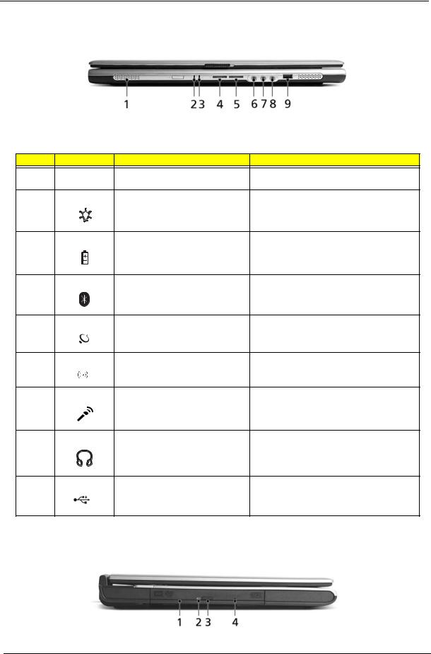
Closed front view
# |
Icon |
Item/ Port |
Description |
1 |
|
Speakers |
Left and right speakers deliver stereo audio |
|
|
|
output. |
2 |
|
Power indicator |
Lights up when the computer is on. |
3 |
|
Battery indicator |
Lights up when the battery is being charged. |
4 |
|
Bluetooth communication button/ |
Press to enable/disable the Bluetooth function. |
|
|
indicator (for selected models) |
Indicates the status of Bluetooth communication |
|
|
|
(optional). |
5 |
|
Wireless communication button/ |
Press to enable/disable the wireless function. |
|
|
indicator |
Indicates the status of wireless LAN |
|
|
|
communication (optional). |
6 |
|
Line-in jack |
Accepts audio line-in devices (e.g., audio CD |
|
|
|
player, stereo walkman). |
7 |
|
Mic-in jack |
Accepts inputs from external microphones. |
8 |
|
Speaker/Line-Out/Headphone jack |
Connects to audio line-out devices (e.g., |
|
|
|
speakers, headphones). |
9 |
|
USB 2.0 port |
Connects to Universal Serial Bus (USB) 2.0 |
|
|
|
devices (e.g., USB mouse, UsB camera). |
Left view
Chapter 1 |
9 |

# |
Icon |
Item/ Port |
Description |
|
|
|
|
1 |
|
Optical drive |
Internal optical drive; accepts CDs or DVDs |
|
|
|
depending on the optical drive type. |
|
|
|
|
2 |
|
LED indicator |
Lights up when the optical drive is active. |
|
|
|
|
3 |
|
Emergency eject hole |
Ejects the optical drive tray when the computer is |
|
|
|
turned off. |
|
|
|
|
4 |
|
Optical drive eject button |
Ejects the optical drive tray from the drive. |
|
|
|
|
Right view
# |
Icon |
Item/ Port |
Description |
||||||
|
|
|
|
|
|
|
|
|
|
1 |
|
|
|
|
|
|
|
PC Card slot eject button |
Ejects the PC Card from the slot |
|
|
|
|
|
|
|
|
|
|
2 |
|
|
|
|
|
|
|
PC card slot |
Accepts one Type II CardBus PC Card. |
|
|
|
|
|
|
|
|
|
|
|
|
|
|
|
|
|
|
|
|
|
|
|
|
|
|
|
|
|
|
3 |
|
|
|
|
|
|
|
USB 2.0 port |
Connects to Universal Serial Bus (USB) 2.0 |
|
|
|
|
|
|
|
|
|
devices (e.g., USB mouse, USB camera). |
|
|
|
|
|
|
|
|
|
|
4 |
|
|
|
|
|
|
|
Network jack |
Connects to an Ethernet 10/100 based |
|
|
|
|
|
|
|
|
|
network. |
|
|
|
|
|
|
|
|
|
|
5 |
|
|
|
|
|
|
|
Modem jack |
Connects to a phone line. |
|
|
|
|
|
|
|
|
|
|
6 |
|
|
|
|
|
|
|
Ventilation slots |
Enable the computer to stay cool, even after |
|
|
|
|
|
|
|
|
|
prolonged use. |
|
|
|
|
|
|
|
|
|
|
Rear view
10 |
Aspire 3000/3500//5000 |

# |
|
Icon |
Port |
Description |
|||||
|
|
|
|
|
|
|
|
|
|
1 |
|
|
|
|
|
|
|
Power jack |
Connects to an AC adaptor. |
|
|
|
|
|
|
|
|
|
|
|
|
|
|
|
|
|
|
|
|
|
|
|
|
|
|
|
|
|
|
|
|
|
|
|
|
|
|
|
|
2 |
|
|
|
|
|
|
|
External display port |
Connects to a display device (e.g., external |
|
|
|
|
|
|
|
|
|
monitor, LCD projector). |
|
|
|
|
|
|
|
|
|
|
3 |
|
|
|
|
|
|
|
Security keylock |
Connects to a Kensington-compatible |
|
|
|
|
|
|
|
|
|
computer security lock. |
|
|
|
|
|
|
|
|
|
|
Bottom view
# |
Item |
Description |
|
|
|
1 |
Hard disc bay |
Houses the computer’s hard disc (secured by a screw). |
|
|
|
2 |
Battery release latch |
Unlatches the battery to remove the battery pack. |
|
|
|
3 |
Battery bay |
Houses the computer’s battery pack. |
|
|
|
4 |
Battery lock |
Locks the battery in place. |
|
|
|
5 |
Cooling fan |
Helps keep the computer cool. |
|
|
Note: Do not cover or obstruct the opening of the fan. |
|
|
|
6 |
Memory comparment |
House the computer’s main memory. |
|
|
|
Chapter 1 |
11 |
Indicators
The computer has three easy-to-read status icons on the upper-right above the keyboard, and four on the front panel.
# |
Icon |
Function |
Description |
1 |
|
Caps Lock |
Lights when Caps Lock is activated. |
2 |
|
Num Lock |
Lights when Numeric Lock is activated. |
|
|
(Fn-F11) |
|
3 |
|
Media activity |
Indicates when the hard disk or optical |
|
|
|
drive is active. |
|
|
Bluetooth |
Indicates the status of Bluetooth |
|
|
|
communication. |
|
|
Wireless LAN |
Indicates the status of Bluetooth |
|
|
|
communication. |
4 |
|
Power |
Lights when the computer is on. |
5 |
|
Battery |
Lights when the battery is being charged. |
NOTE: 1. Charging: the light shows amber when the battery is charging.
NOTE: 2. Fully charged: light shows green when in AC mode.
12 |
Aspire 3000/3500//5000 |
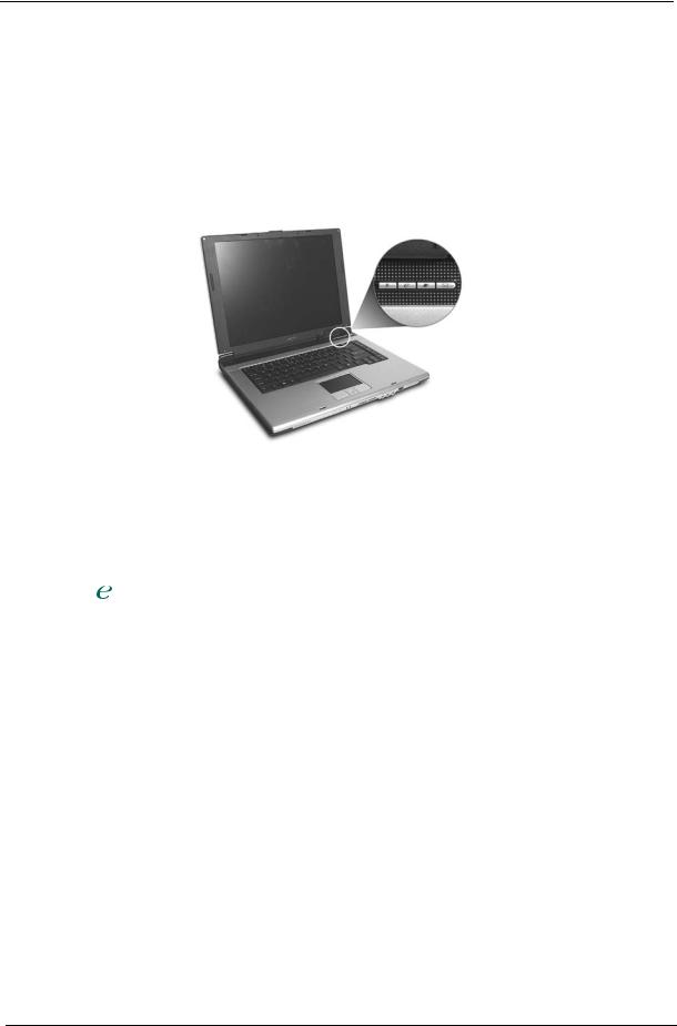
Launch Keys
Located at the upper-right, above the keyboard are four buttons. These buttons are called launch keys. They are mail, Web browser, Acer Empowering key “  “, and one user-programmable button.
Press “  “ to run the Acer eManager. The mail and Web buttons are pre-set ot email and internet programs, but can be reset by users. To set the Web browser, mail and programmable keys, run the Acer Launch Manager.
Launch key |
Default application |
|
|
P |
User-programmable |
|
|
|
Acer eManager (user-programmable) |
|
|
Web browser |
Internet browser (user-programmable) |
|
|
Email application (user-programmable) |
|
|
|
Chapter 1 |
13 |

Using the keyboard
The keyboard has full-sized keys and an embedded keypad, separate cursor keys, two Windows keys and twelve function keys.
Lock keys and embedded numeric keypad
The keyboard has three lock keys which you can toggle on and off.
Lock key |
Description |
|
|
Caps Lock |
When @is on, all alphabetic characters typed are in uppercase. |
@ |
|
|
|
Num Lock (Fn-F11) |
When ]is on, the embedded keypad is in numeric mode. The keys function |
] |
as a calculator (complete with the arithmetic operators ), -, *, and /). Use this mode |
|
when you need to do a lot of numeric data entry. A better solution would be to |
|
connect an external keypad. |
|
|
Scroll Lock (Fn-F12) |
When [is on, the screen moves one line up or down when you press the up |
[ |
or down arrow keys respectively. [does not work with some applications. |
|
|
The embedded numeric keypad functions like a desktop numeric keypad. It is indicated by small characters located on the upper right corner of the keycaps. To simplify the keyboard legend, cursor-control key symbols are not printed on the keys.
|
Desired access |
Num lock on |
Num lock off |
|
|
|
|
|
|
|
Number keys on embedded |
Type numbers in a normal manner. |
|
|
|
keypad |
|
|
|
|
|
|
|
|
|
Cursor-control keys on embedded |
Hold <Shift> while using cursor-control |
Hold <Fn> while using cursor- |
|
|
keypad |
keys. |
control keys. |
|
|
|
|
|
|
|
|
|
|
|
14 |
Aspire 3000/3500//5000 |

Desired access |
Num lock on |
Num lock off |
|
|
|
Main keyboard keys |
Hold <Fn> while typing letters on embedded |
Type the letters in a normal manner. |
|
keypad. |
|
|
|
|
Windows keys
The keyboard has two keys that perform Windows-specific functions.
Keys |
|
Description |
|
|
|
Windows logo key |
Start button. Combinations with this key perform shortcut functions. Below |
|
|
are a few examples: |
|
|
+ <Tab> (Activates the next Taskbar button) |
|
|
+ <E> (Opens the My Computer window) |
|
|
+ <F1> (Opens Help and Support) |
|
|
+ <F> (Opens the Find: All Files dialog box) |
|
|
+ <R> (Opens the Run dialog box) |
|
|
+ <M> (Minimizes all windows) |
|
|
<shift>+ |
+< M> (Undoes the minimize all windows) |
|
|
|
Application key |
This key has the same effect as clicking the right mouse button; it opens the |
|
|
application’s context menu. |
|
|
|
|
Hot Keys
The computer employs hot keys or key combinations to access most of the computer’s controls like screen contrast and brightness, volume output and the BIOS Utility.
To activate hot keys, press and hold the <Fn> key before pressing the other key in the hot key combination.
Chapter 1 |
15 |

Hot Key |
Icon |
Function |
Description |
Fn-l |
|
Hotkey help |
Displays a list of the hotkeys and their functions. |
Fn-m |
|
Acer eSetting |
Launches Acer eSetting in Acer eManager. |
Fn-n |
|
Acer Power |
Launches Power Management options. |
|
|
Management |
|
Fn-o |
|
Sleep |
Puts the computer in Sleep mode. |
Fn-p |
|
Display toggle |
Switches display output between the display screen, |
|
|
|
external monitor (if connected) and both the display |
|
|
|
screen and external monitor. |
Fn-q |
|
Screen blank |
Turns the display screen backlight off to save power. |
|
|
|
Press any key to return. |
Fn-r |
|
Touchpad Toggle |
Turns the internal touchpad on and off. |
Fn-s |
|
Speaker on/off |
Turns the speakers on and off; mutes the sound. |
Fn-w |
|
Volume up |
Increases the sound volume. |
Fn-y |
|
Volume down |
Decreases the sound volume. |
Fn-x |
|
Brightness up |
Increases the screen brightness. |
Fn-¨z |
|
Brightness down |
Decreases the screen brightness. |
Special keys
You can locate the Euro symbol at the upper-center (for European keyboard) and/or bottom-right (Chinese keyboard) of your keyboard. To type:
16 |
Aspire 3000/3500//5000 |

The Euro symbol
1.Open a text editor or word processor.
2.Either directly press the <Euro> key at the bottom-right of the keyboard (for Chinese keyboard), or hold <Alt Gr> and then press the <5> key at the upper-center of the keyboard.symbol at the upper-center of the keyboard (for European keyboard, you can use both method).
NOTE: Some fonts and software do not support the Euro symbol. Please refer to www.microsoft.com/ typography/faq/faq12.htm for more information.
The US dollar sign
1.Open a text editor or word processor.
2.Either directly press the <Euro> key at the bottom-right of the keyboard (for Chinese keyboard), or hold <Shift> and then press the <4> key at the upper-center of the keyboard.symbol at the upper-center of the keyboard (for European keyboard, you can use both method).
NOTE: This function varies according to the language settings.
Chapter 1 |
17 |

Touchpad
The built-in touchpad is a pointing device that senses movement on its surface. This means the cursor responds as you move your finger on the surface of the touchpad. The central location on the palmrest provides optimum comfort and suuport.
Touchpad basics
The following items teach you how to use the touchpad:
*Move your finger across the touchpad (2) to move the cursor.
*Press the left (1) and right (4) buttons located on the edge of the touchpad to do selection and execution functions. These two buttons are similar to the left and right buttons on a mouse. Tapping on the touchapd is the same as clicking the left button.
*Use the 4-wa scroll (3) button to scroll up or down and move left or right a page. This button mimics your cursor pressing on the right scroll bar of Windows applications.
18 |
Aspire 3000/3500//5000 |

Function |
Left button (1) |
Right button (4) |
Touchpad (2) |
Center button (3) |
|
|
|
|
|
Execute |
Click twice quickly. |
|
Tap twice (at the same speed |
|
|
|
|
as double-clicking a mouse |
|
|
|
|
button). |
|
|
|
|
|
|
Select |
Click once. |
|
Tap once. |
|
|
|
|
|
|
Drag |
Click and hold, |
|
Tap twice (at the same speed |
|
|
then use finger to |
|
as double-clicking a mouse |
|
|
drag the cursor on |
|
button); hold finger to the |
|
|
the touchpad. |
|
touchpad on the second tap |
|
|
|
|
and drag the cursor. |
|
|
|
|
|
|
Access |
|
Click once. |
|
|
context menu |
|
|
|
|
|
|
|
|
|
Scroll |
|
|
|
Click and hold to |
|
|
|
|
move up/down/left/ |
|
|
|
|
right. |
|
|
|
|
|
NOTE: Keep your fingers dry and clean when using the touchpad. Also keep the touchpad dry and clean. The touchpad is sensitive to finger movement, hence, the lighter the touch, the better the response. Taping harder will not increase the touchpad’s responsiveness.
Chapter 1 |
19 |

Hardware Specifications and Configurations
System Board Major Chip
Item |
Controller |
|
|
System core logic |
SiS M760GX+SiS 963L for Aspire 3000/5000 |
|
SiS M661MX+SiS 963L for Aspire 3500 |
|
|
Audio controller |
RealTek ALC203 AC 97 Codec |
|
|
Video controller |
built-in SiS M760GX for Aspire 300/5000 |
|
built-in SiS M661MX for Aspire 3500 |
|
|
Keyboard controller |
KB910 |
|
|
CardBus Controller |
ENE CB712 |
|
|
IEEE Controller |
VIA VT6301S |
|
|
Processor
Item |
Specification |
|
|
CPU type |
Mobile AMD Turion 64 processor ML-28/ML-30 or higher for Aspire 5000 |
|
Mobile AMD Sempron processor 2600+ to 3000+ or higher for Aspire 3000 |
|
Intel® Celeron® M 350/360/370 processor at 1.3/1.4/1.5 GHz, 400 MHz FSB |
|
for Aspire 3500 series |
|
Intel® Pentium® M 715 processor at 1.5 GHz, 400 MHz FSB for Aspire 3500 |
|
series |
|
|
CPU package |
SMT µ PGA 754 pin |
|
|
CPU core voltage |
Low speed: 0.8V |
|
High speed: 1.5V |
|
|
CPU I/O voltage |
1.2V |
|
|
BIOS |
|
|
|
Item |
Specification |
|
|
BIOS vendor |
Pheonix BIOS |
|
|
BIOS Version |
Aspire 3000 V1.00; Aspire 5000 V1.00; AS3500 V1.00 |
|
|
BIOS ROM type |
Flash ROM |
|
|
BIOS ROM size |
|
|
|
BIOS package |
32 Pin PLCC |
|
|
Supported protocols |
ACPI 2.0 (if available, at least 1.0b), SMBIOS 2.3, PCI 2.2, Boot Block, |
|
PXE 2.0, Mobile PC2001, Hard Disk Password, INT 13h Extensions, PCI |
|
Bus Power Management interface Specification, EI Torito-Bootable CD- |
|
ROM Format Specification V1.0, Simple Boot Flag 1.0 |
|
|
BIOS password control |
Set by switch, see SW1 settings |
|
|
Second Level Cache |
|
|
|
Item |
Specification |
|
|
Cache controller |
Built-in CPU |
|
|
20 |
Aspire 3000/3500//5000 |

Second Level Cache
Item |
Specification |
Cache size |
1024KB/512KB (exclusive) |
|
total effective cache: 1152KB/640KB for Mobile AMD Turion 64 processor |
|
(Aspire 5000) |
|
256KB/128KB (exclusive) |
|
total effective cache: 384KB/256KB for Mobile AMD Sempron processor |
|
(Aspire 3000) |
|
512KB for Intel® Celeron® M processor (Aspire 3500) |
|
2MB for Intel® Pentium® M processor (Aspire 3500) |
1st level cache control |
Always Enabled |
|
|
2nd level cache control |
Always Enabled |
|
|
Cache scheme control |
Fixed-in write back |
|
|
System Memory
Item |
Specification |
|
|
Memory controller |
built-in CPU |
|
Mobile AMD Turion 64 processor ML-28/ML-30 or higher for Aspire 5000 |
|
Mobile AMD Sempron processor 2600+ to 3000+ or higher for Aspire 3000 |
|
Intel® Celeron® M 350/360/370 processor at 1.3/1.4/1.5 GHz, 400 MHz |
|
FSB for Aspire 3500 series |
|
Intel® Pentium® M 715 processor at 1.5 GHz, 400 MHz FSB for Aspire |
|
3500 series |
|
|
Onboard memory size |
0MB |
|
|
DIMM socket number |
2 Sockets |
|
|
Supports memory size per socket |
256MB |
|
|
Supports maximum memory size |
2048MB |
|
|
Supports DIMM type |
DDR-DRAM |
|
|
Supports DIMM Speed |
333 MHz |
|
|
Supports DIMM voltage |
2.5 V/1.25V |
|
|
Supports DIMM package |
200-pin so-DIMM |
|
|
Memory module combinations |
You can install memory modules in any combinations as long as they |
|
match the above specifications . |
|
|
Memory Combinations
Slot 1 |
Slot 2 |
Total Memory |
|
|
|
0MB |
256MB |
256MB |
|
|
|
0MB |
512MB |
512MB |
|
|
|
0MB |
1024MB |
1024MB |
|
|
|
256MB |
0MB |
256MB |
|
|
|
256MB |
256MB |
512MB |
|
|
|
256MB |
512MB |
768MB |
|
|
|
256MB |
1024MB |
1280MB |
|
|
|
512MB |
0MB |
512MB |
|
|
|
512MB |
256MB |
768MB |
|
|
|
512MB |
512MB |
1024MB |
|
|
|
512MB |
1024MB |
1536MB |
|
|
|
1024MB |
0MB |
1024MB |
|
|
|
Chapter 1 |
21 |
Loading...