


Asidea 500
Table of contents
 Loading...
Acer
Aspire iDea 500/510 Series
Service Guide
Service guide files and updates are
available on the ACER/CSD web. For
more information, please refer to http://
csd.acer.com.tw
PRINTED IN TAIWAN

Revision History
Please refer to the table below for the updates of Desktop Aspire iDea 500/510 service guide.
Date Chapter Updates
October 30, 2006 first release
II

Copyright
Copyright© 2006 by Acer Incorporated. All rights reserved. No part of this publication may be
reproduced, transmitted, transcribed, stored in a retrieval system, or translated into any language or
computer language, in any form or by any means, electronic, mechanical, magnetic, optical, chemical,
manual or otherwise, without the prior written permission of Acer Incorporated.
III

Disclaimer
The information in this guide is subject to change without notice.
Acer Incorporated makes no representations or warranties, either expressed or implied, with respect to
the contents hereof and specifically disclaims any warranties of merchantability or fitness for any
particular purpose. Any Acer Incorporated software described in this manual is sold or licensed “as is”.
Should the programs prove defective following their purchase, the buyer (and not Acer Incorporated,
its distributor, or its dealer) assumes the entire cost of all necessary servicing, repair, and any
incidental or consequential damages resulting from any defect in the software.
Acer is a registered trademark of Acer Incorporated.
Other brand and product names are trademarks and/or registered trademarks of their respective
holders.
IV

Conventions
The following conventions are used in this manual:
SCREEN MESSAGES Denotes actual messages that appear on screen.
NOTE Gives bits and pieces of additional information related to the
current topic.
WARNING Alerts you to any damage that might result from doing or not
doing specific actions.
CAUTION Gives precautionary measures to avoid possible hardware
or software problems.
IMPORTANT Reminds you to do specific actions relevant to the
accomplishment of procedures.
V

Preface
Before using this information and the product it supports, please read the following general information.
1. This Service Guide provides you with all technical information relating to the BASIC
CONFIGURATION decided for Acer's “global” product offering. To better fit local market
requirements and enhance product competitiveness, your regional office MAY have decided to
extend the functionality of a machine (e.g. add-on card, modem, or extra memory capability). These
LOCALIZED FEATURES will NOT be covered in this generic service guide. In such cases, please
contact your regional offices or the responsible personnel/channel to provide you with further
technical details.
2. Please note WHEN ORDERING FRU PARTS, you should check the most up-to-date information
available on your regional web or channel. For whatever reason, if a part number change is made, it
will not be noted in the printed Service Guide. For ACER-AUTHORIZED SERVICE PROVIDERS,
your Acer office may have a DIFFERENT part number code to those given in the FRU list of this
printed Service Guide. You MUST use the list provided by your regional Acer office to order FRU
parts for repair and service of customer machines.
VI

Table of Contents
Chapter 1 System Specification 1
Specification . . . . . . . . . . . . . . . . . . . . . . . . . . . . . . . .1
Operating System . . . . . . . . . . . . . . . . . . . . . . . . . . . . . . 1
Platform . . . . . . . . . . . . . . . . . . . . . . . . . . . . . . . . . . . . . . 1
System Memory . . . . . . . . . . . . . . . . . . . . . . . . . . . . . . . 1
Storage Subsystem . . . . . . . . . . . . . . . . . . . . . . . . . . . . . 1
Audio . . . . . . . . . . . . . . . . . . . . . . . . . . . . . . . . . . . . . . . . 1
Communication and Receiver . . . . . . . . . . . . . . . . . . . . . 1
TV Tuner Subsystem . . . . . . . . . . . . . . . . . . . . . . . . . . . 2
Display Subsystem . . . . . . . . . . . . . . . . . . . . . . . . . . . . . 2
DV Camcorder Processing . . . . . . . . . . . . . . . . . . . . . . . 2
Front Panel Indicators and Buttons . . . . . . . . . . . . . . . . . 2
I/O Interface . . . . . . . . . . . . . . . . . . . . . . . . . . . . . . . . . . 2
Power Subsystem . . . . . . . . . . . . . . . . . . . . . . . . . . . . . . 3
Acoustic Estimation . . . . . . . . . . . . . . . . . . . . . . . . . . . . . 3
Dimension and Weight . . . . . . . . . . . . . . . . . . . . . . . . . . 4
Block Diagram . . . . . . . . . . . . . . . . . . . . . . . . . . . . . . .5
Main Board Placement . . . . . . . . . . . . . . . . . . . . . . . .6
Front Panel View . . . . . . . . . . . . . . . . . . . . . . . . . . . . .9
Rear Panel View . . . . . . . . . . . . . . . . . . . . . . . . . . . .11
Remote Control . . . . . . . . . . . . . . . . . . . . . . . . . . . . .12
Using the Remote Control . . . . . . . . . . . . . . . . . . . . . . . 13
Wireless Keyboard . . . . . . . . . . . . . . . . . . . . . . . . . .14
Setting up the System . . . . . . . . . . . . . . . . . . . . . . . .16
Connecting the Power Cable . . . . . . . . . . . . . . . . . . . . 16
Connecting Display Devices . . . . . . . . . . . . . . . . . . . . . 17
Connecting to a TV Antenna or Cable . . . . . . . . . . . . . 20
Connecting an FM Radio Antenna . . . . . . . . . . . . . . . . 20
Connecting Audio Devices . . . . . . . . . . . . . . . . . . . . . . 21
Configuring Audio Output Settings . . . . . . . . . . . . . . . . 22
Setting up the Wireless Devices . . . . . . . . . . . . . . . . . . 22
Windows XP Media Center . . . . . . . . . . . . . . . . . . . .24
Opening Media Center . . . . . . . . . . . . . . . . . . . . . . . . . 24
Media Center Home Page . . . . . . . . . . . . . . . . . . . . . . 24
Configuring Your Set-Top Box . . . . . . . . . . . . . . . . . . . 25
Closing Media Center . . . . . . . . . . . . . . . . . . . . . . . . . . 25
Acer eRecovery Management . . . . . . . . . . . . . . . . . .26
Launching Acer eRecovery Management . . . . . . . . . . . 26
Copying the Factory Default Settings Image . . . . . . . . 26
Creating System Backups . . . . . . . . . . . . . . . . . . . . . . . 26
Creating an Incremental Backup . . . . . . . . . . . . . . . . . . 27
TOC VII

Copying to Disks . . . . . . . . . . . . . . . . . . . . . . . . . . . . . . 27
Restoring the System . . . . . . . . . . . . . . . . . . . . . . . . . . 27
Other System Restore Modes . . . . . . . . . . . . . . . . . . . . 28
Acer ePerformance Management . . . . . . . . . . . . . . .30
Acer ePerformance Management Main Page . . . . . . . . 30
Hardware Specification and Configuration . . . . . . . .31
Power Management Function (ACPI Support Function)
. . . . . . . . . . . . . . . . . . . . . . . . . . . . . . . . . . . . . . . . . .36
Device Standby Mode . . . . . . . . . . . . . . . . . . . . . . . . . . 36
Global Standby Mode . . . . . . . . . . . . . . . . . . . . . . . . . . 36
Suspend Mode . . . . . . . . . . . . . . . . . . . . . . . . . . . . . . . 36
ACPI . . . . . . . . . . . . . . . . . . . . . . . . . . . . . . . . . . . . . . . 36
Chapter 2 Setup Utility 37
About the Setup Utility . . . . . . . . . . . . . . . . . . . . . . . .37
The Standard Configuration . . . . . . . . . . . . . . . . . . . . . 37
Entering the Setup Utility . . . . . . . . . . . . . . . . . . . . . . . 38
Product Information . . . . . . . . . . . . . . . . . . . . . . . . . .39
Standard CMOS Features . . . . . . . . . . . . . . . . . . . . .40
Advanced BIOS Features . . . . . . . . . . . . . . . . . . . . .41
Advanced Chipset Features . . . . . . . . . . . . . . . . . . .43
Integrated Peripherals . . . . . . . . . . . . . . . . . . . . . . . .44
Power Management Setup . . . . . . . . . . . . . . . . . . . . 46
PnP/PCI Configuration . . . . . . . . . . . . . . . . . . . . . . .48
PC Health Status . . . . . . . . . . . . . . . . . . . . . . . . . . . .50
Frequency/Voltage Control . . . . . . . . . . . . . . . . . . . .51
Load Default Settings . . . . . . . . . . . . . . . . . . . . . . . .52
Set Supervisor/User Password . . . . . . . . . . . . . . . . .53
Save and Exit Setup . . . . . . . . . . . . . . . . . . . . . . . . . . . 54
Exit without Saving . . . . . . . . . . . . . . . . . . . . . . . . . . . . 54
Chapter 3 Machine Disassembly and Replacement 55
General Information . . . . . . . . . . . . . . . . . . . . . . . . .55
Before You Begin . . . . . . . . . . . . . . . . . . . . . . . . . . . . . 55
Disassembly Procedure . . . . . . . . . . . . . . . . . . . . . .56
Removing the Memory . . . . . . . . . . . . . . . . . . . . . . . . . 56
Removing the Upper Case . . . . . . . . . . . . . . . . . . . . . . 56
Removing the ODD Module . . . . . . . . . . . . . . . . . . . . . 57
Removing the HDD Module . . . . . . . . . . . . . . . . . . . . . 58
Removing the System Power Supply . . . . . . . . . . . . . . 58
Removing the RCA Board . . . . . . . . . . . . . . . . . . . . . . . 59
Removing the Add-on Cards . . . . . . . . . . . . . . . . . . . . . 60
VIII TOC

Removing the MXM Card . . . . . . . . . . . . . . . . . . . . . . . 62
Removing the VFD Board . . . . . . . . . . . . . . . . . . . . . . . 63
Removing the Wireless Keyboard Module and the Bluetooth Module
. . . . . . . . . . . . . . . . . . . . . . . . . . . . . . . . . . . . . . . . . . . . 64
Removing the CPU Fan . . . . . . . . . . . . . . . . . . . . . . . . 64
Removing the Card Reader Board . . . . . . . . . . . . . . . . 65
Removing the Main Board and the Split Board . . . . . . . 66
Chapter 4 Troubleshooting 67
Chapter 5 Jumper and Connector Information 68
Introduction of Connectors . . . . . . . . . . . . . . . . . . . .68
Upper Side of Main Board . . . . . . . . . . . . . . . . . . . . . . . 68
Lower Side of Main Board . . . . . . . . . . . . . . . . . . . . . . . 69
Jumper Setting and Power button . . . . . . . . . . . . . . . . . 70
Chapter 6 FRU (Field Replaceable Unit) List 71
Parts . . . . . . . . . . . . . . . . . . . . . . . . . . . . . . . . . . . . .72
TOC IX

System Specification
Specification
Operating System
• Microsoft
Platform
• Intel
1.66/1.83/2.0/2.16/2.83GHz, FSB 667MHz)
• Intel
System Memory
• 256, 512 or 1024MB of DDR2 533/667MHz memory
• Dual channel
• Upgradeable to 2GB using two soDIMM modules
®
Windows® XP Media Center Edition 2005 Rollup 2 (Emerald)
®
Core Duo processor (Merom dual core) T5500/T5600/T7200/T7400/T7600 (2MB/4MB L2 cache,
®
i945GT + ICH7M-DH chipset
Chapter 1
Storage Subsystem
• 250/320/400/500GB 3.5” hard disk drive, SATA-II with NCQ
• Slot-loading optical drive: DVD Dual or DVD Super Multi
• Two card reader slots, XD/ SD/ MMC/ MS/ MS PRO/ MD/ CF-I/ CF-II/ MD support
• Playback media support: CD, VCD, SVCD, CD-R/RW, DVD, DVD-DL, DVD-R, DVD-RW, DVD-R DL,
DVD+R, DVD+RW, DVD+R DL (DVD-RAM support if with DVD Super Multi)
• Recording media support: CD-R/RW, DVD-R, DVD-RW, DVD-R DL, DVD+R, DVD+RW, DVD+R DL
(DVD-RAM support if with DVD Super Multi)
Audio
• Controller: Realtek ALC888DD
®
• HD Audio, Dolby
• 7.1-CH analog output with S/PDIF support for digital output
• Dolby
• DTS Neo PC virtual surround to analog and digital output support
• Audio digital to analog converter: 24bit/193KHz (10 DACs in total)
• Audio playback file format support: CD-Audio (cda), Windows Media (asf/ asx/ wax/ wm/ wma/ wmd),
®
Digital surround 5.1-CH decoding and DTS digital output support
Windows audio format (wav/ wmp/ wmx/ wvx) and MP3 (mp3/ m3u)
Digital Live and DTS connect support
Communication and Receiver
• LAN controller: Intel
• WLAN: 802.11b/g mini-PCI card with external antenna
• WPAN: internal USB Bluetooth module
• IR: internal beam-bag MCE compliant RC6 receiver with dual IR emitters
®
82573L (Vidalia), GbE Ethernet; Wake-on-LAN ready
Chapter 1 1

• Wireless keyboard: internal 2.4GHz RF wireless keyboard receiver with auto-pairing technology
TV Tuner Subsystem
• Support up to two hybrid mini-PCI TV tuner cards for simultaneous TV viewing and recording (2x Analog
or 2x DVB-T
• 3D Y-C comb filter support
• World wide tuner all PAL/SECAM and NTSC TV format support
• MPEG2 file format real time recording to HDD (200GB free space provides total 160 hours recording with
fair quality setting: 71 hours recording with the best quality setting) support
• Time shifting support
• Up to three sets of S-A/V input selection support
Display Subsystem
• Add-on MXM card of nVidia GeForce Go 7600 (NB7P-GS, P478, G73M with HDMI version)
• High definition display support
• Component TV output (YPbPr): 480p/ 720p/ 1080i/ 1080p
• Progressive VGA-output: 32bit/400MHz digital to analog converter, up to QXGA (2048 x 1536)
• DVI output (with HDCP support): 640 x 480, 800 x 600, 1024 x 768, 1152 x 864, 1280 x 600, 1280 x 720,
1280 x 768, 1280 x 960, 1280 x 1024, 1440 x 900, 1440 x 1050, 1600 x 900, 1600 x 1200, 1680 x 1050,
1920 x 1080, 1920 x 1200
• HDMI output (with HDCP support): 480p/ 720p/ 1080i/ 1080p
• Video playback file format support: Windows media (asf/ wmv), Windows video format (avi), movie file
(mpeg/ mpg/ mpe/ m1v/ mpv2/ mpa) and Windows Metafile (wmf)
• Picture playback file format support: jpeg/ jpg/ tif/ gif/ bmp/ wmf/ png
DV Camcorder Processing
• Transfer DV camcorder content into a DVD-Video disk (with direct mode and editing mode) support
• Transfer DV camcorder content into MPEG2 video file(s) on HDD
Front Panel Indicators and Buttons
• Front panel VFD for MCE status and media title display
• Media control keys: Stop, Play/Pause, Previous/REW, Next/FF and Rec
• MCE Navigation buttons: Up, Down, Left, Right, OK, Back
• Power button with power status LED
• Normal working: blue
• Away mode: amber-blinking
• S3: amber
• S4/S5: off
I/O Interface
Rear I/O
• Audio/Video output
• One coaxial S/PDIF and 1 optical S/PDIF
• One set of 7.1-channel (RCA)
• One HDMI: HDCP support
2 Chapter 1

• One DVI-I: HDCP support, using DVI to VGA adapter for VGA output
• One set of component (Y Pb Pr) (RCA)
• One S-Video out
• One Composite video out (RCA)
• Audio/Video input
• Two S-Video in (non-EMEA SKU)
• Two Composite in (RCA, non-EMEA SKU)
• Two Stereo in (RCA, non-EMEA SKU)
• SCART ports (EMEA SKU only)
• One SCART-in for S-Video, CVBS, Stereo input
• One SCART-in/out for system’s CVBS, Stereo output and 2
TV tuner SKU)
• Other I/O ports
• One RJ-45 GbE LAN port with LED indicators
• One IEEE 1394a (6-pin)
• Two USB 2.0 ports
• Two IR blaster
• One TV antenna/cable input
• One TV antenna/cable output
• One FM antenna input
• One WLAN external antenna
• One AC inlet
• On MXM slot (optional)
nd
S-Video, CVBS, Stereo input (for dual
Front I/O
• Audio/Video input/output
• One 1/4-inch earphone output
• One 1/4-inch microphone input
• One S-Video in
• One Composite in (RCA)
• One Stereo in (RCA)
• Other I/O ports
• One 4-pin IEEE 1394
• One CF socket for CF-I, CF-II and Micro Drive
• One multi socket for SD/MMC/MS/MS PRO
• Two USB 2.0 ports
• MB expansion slots
• Two memory soDIMM sockets
• Three mini-PCI slots
Power Subsystem
• FSP 120W AC internal power supply unit (FSP120-40GLS)
Acoustic Estimation
• 23 dBA (idle, 1M), 28 dBA (MCE heavy load, 1M)
Chapter 1 3

Dimension and Weight
• 430 (W) x 335 (D) x 70 (H) mm with bezel, feet and WLAN antenna
• Weight: 5.5 Kg
4 Chapter 1
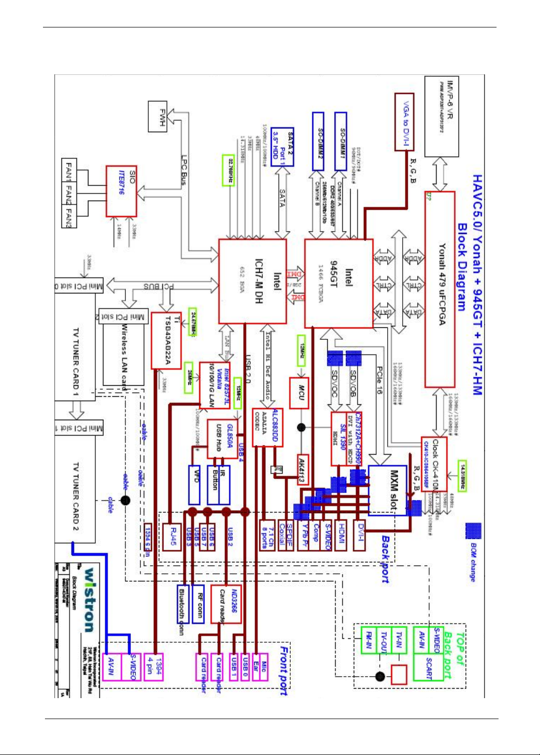
Block Diagram
Chapter 1 5
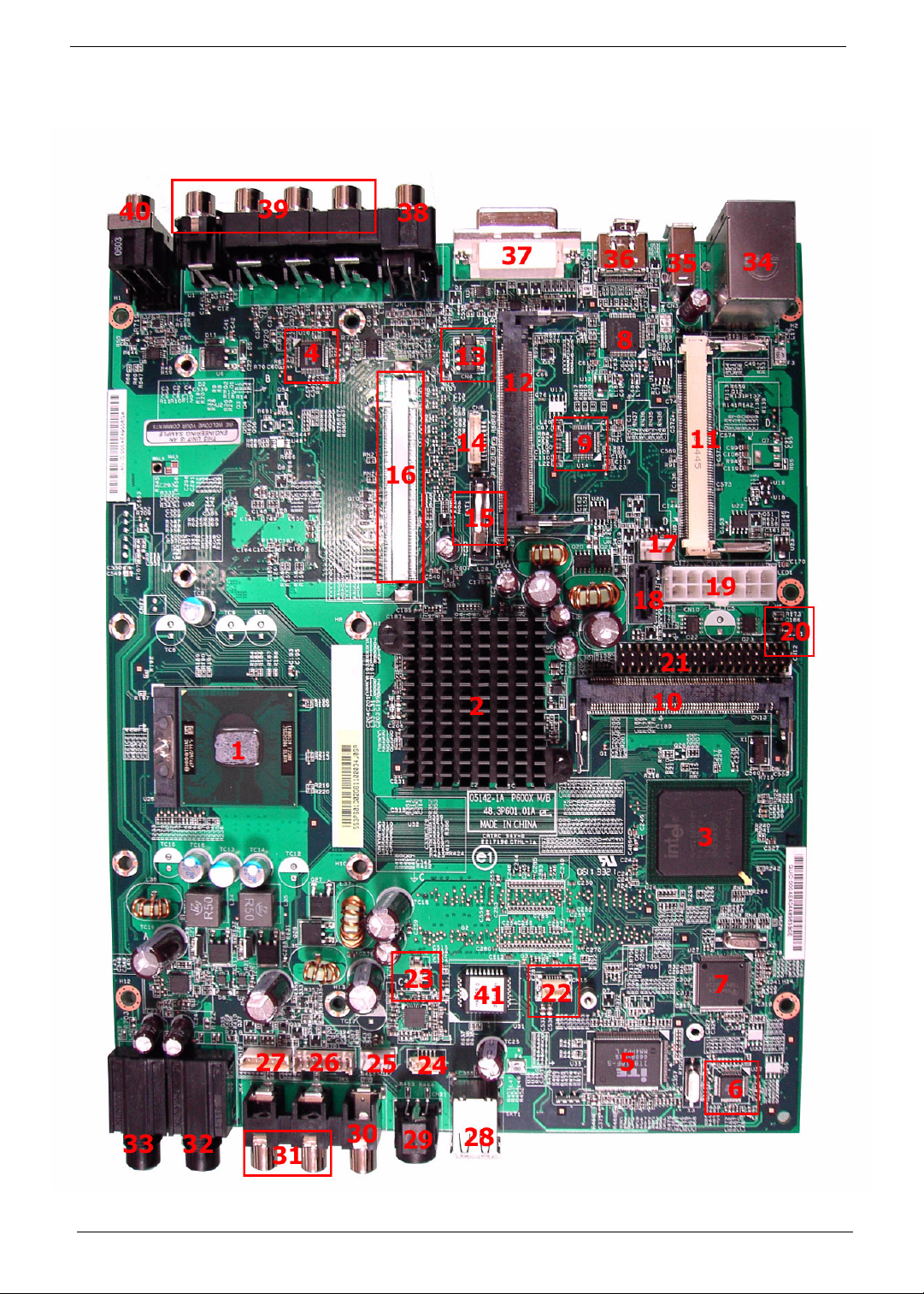
Main Board Placement
6 Chapter 1
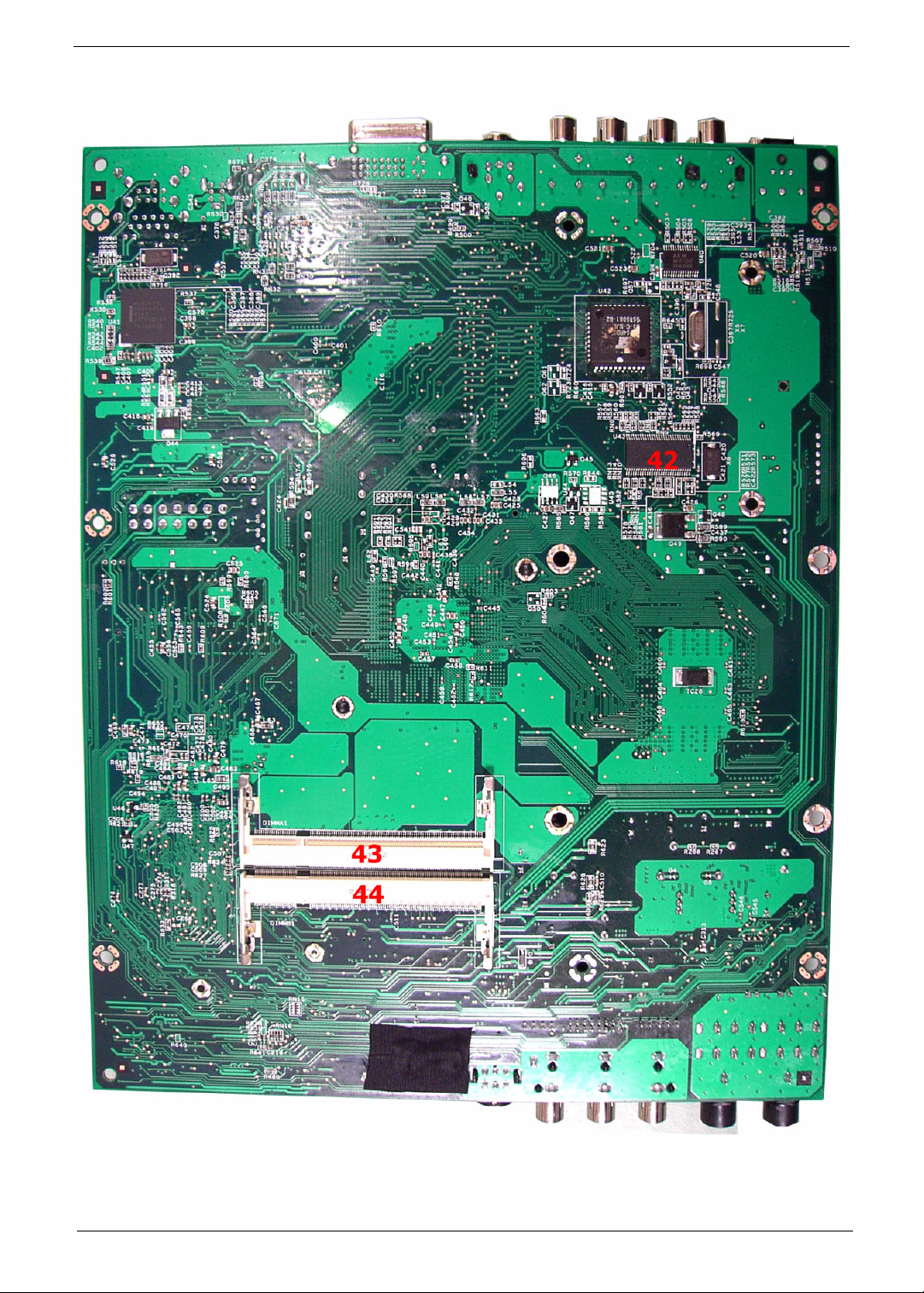
Chapter 1 7
No. Description No. Description
1 CPU socket 2 North bridge
3 South bridge 4 Azalia codec: Realtek ALC883DD
5 Super I/O controller: ITE8716F 6 USB hub: GL850A
7 IEEE 1394: Ti TSB43AB22A 8 Transmitter for HDMI: Silicon Image
1390
9 Transmitter for DVI-I: Chrontel 7313A 10 Mini PCI 1 slot for TV tuner card 1
11 Mini PCI 2 slot for TV tuner card 2 12 Mini PCI 3 slot for WLAN card
13 YPbPr to main board connector 14 SCART to main board connector
15 Battery 16 MXM connector (optional)
17 System fan connector 18 SATA connector
19 14-pin power connector 20 Jumper connector
21 PATA connector 22 Card reader connector
23 Bluetooth connector 24 IR connector
25 CPU fan connector 26 VFD board connector
27 Power button connector 28 USB 2.0 ports
29 S-Video input jack 30 Video input jack
31 Audio input jack 32 1/4” microphone jack
33 1/4” headphone jack 34 RJ-45 port and two USB 2.0 ports
35 6-pin IEEE1394 port 36 USB 2.0 port
37 DVI-I connector 38 Video output jack and S-Video output
jack
39 Multi-channel speaker audio output
connectors
41 BIOS chip: PMC PM49FL004T 42 Clock generator
43 soDIMM slot 44 soDIMM slot
40 Coaxial digital audio output jack
8 Chapter 1
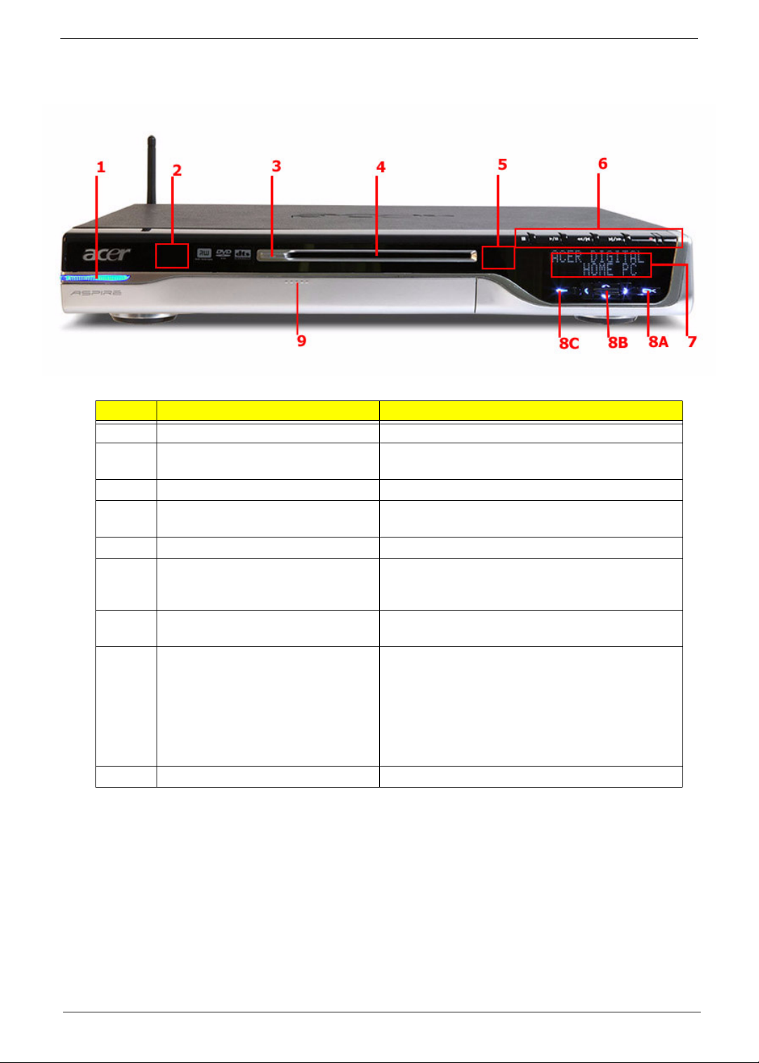
Front Panel View
No. Component Description
1 Power button Press to power on or power off the system.
2 RF (radio frequency) receiver Receives radio frequency from wireless touchpad
3 Drive eject button Ejects the optical disk.
4 Multi writable DVD drive Use to access and record data on compact disks
5 IR (Infrared) receiver Receives IR signals from the remote control.
6 Playback controls Lets you conveniently play, record, pause, stop,
7VFD
(Vacuum Fluorescent display)
8 MCE (Media Center Edition)
navigation buttons
9 I/O ports cover release button Press to open the I/O ports cover.
keyboard.
(CDs) and digital video disks (DVDs)
forward, rewind, skip, or replay a song, slide show,
movie or TV program.
Displays the current Media Center status, current
system date and time, or media title display.
• 8A: Press the Back button to return to the
previous view.
• 8B: Press the Left, Right, Up, or Down arrow
buttons to navigate through the Media Center
menu options.
• 8C: Press the OK button to access the Media
Center menu options and confirm your selection.
Chapter 1 9
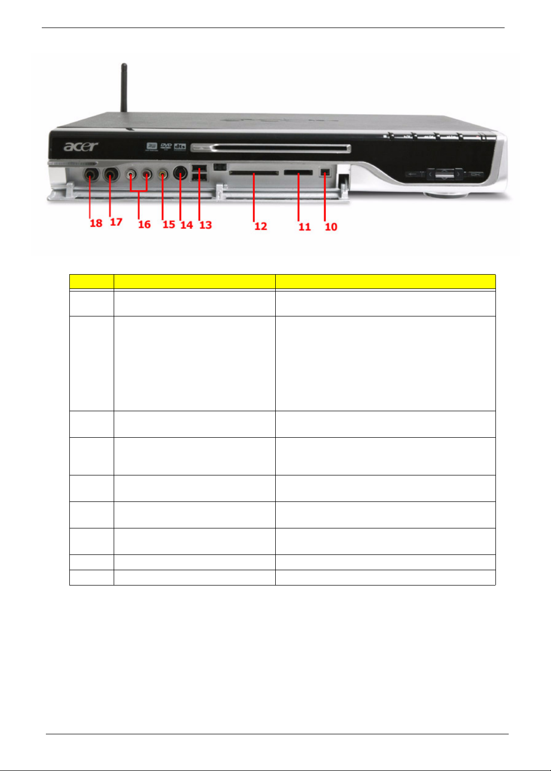
No. Component Description
10 4-pin IEEE 1394 port Connects to an IEEE 1394 device
(e.g., digital video camcorder).
11 XD/SD/MMC/MS/MS PRO slot Accepts an XD (eXtreme Digital), SD (Secure
Digital), MMC (MultiMediaCard), MS (Memory
Stick) or MS PRO (Memory Stick PRO) card.
Warning!
If you want to read contents from
small form factor memory cards, such as
mini-SD, RS-MMC, or MS PRO, you should
use a suitable adaptor.
12 CF-I/CF-II/MD slot Accepts a CF (Compact Flash) Type I, CF Type II
or Microdrive.
13 USB 2.0 ports Connects to USB peripherals devices
(e.g., USB mouse, USB printer, USB combo drive,
digital cameras).
14 S-Video input jack Connects to a video recorder, camcorder, or a
device with S-Video output signal.
15 Video input jack Connects to a video recorder, camcorder, game
console or a device with video output signal.
16 Audio input jack Connects t a video recorder, camcorder, audio
casette player or stereo walkman.
17 1/4” microphone jack Connects to a microphone.
18 1/4” headphone Connects to a headphone.
10 Chapter 1
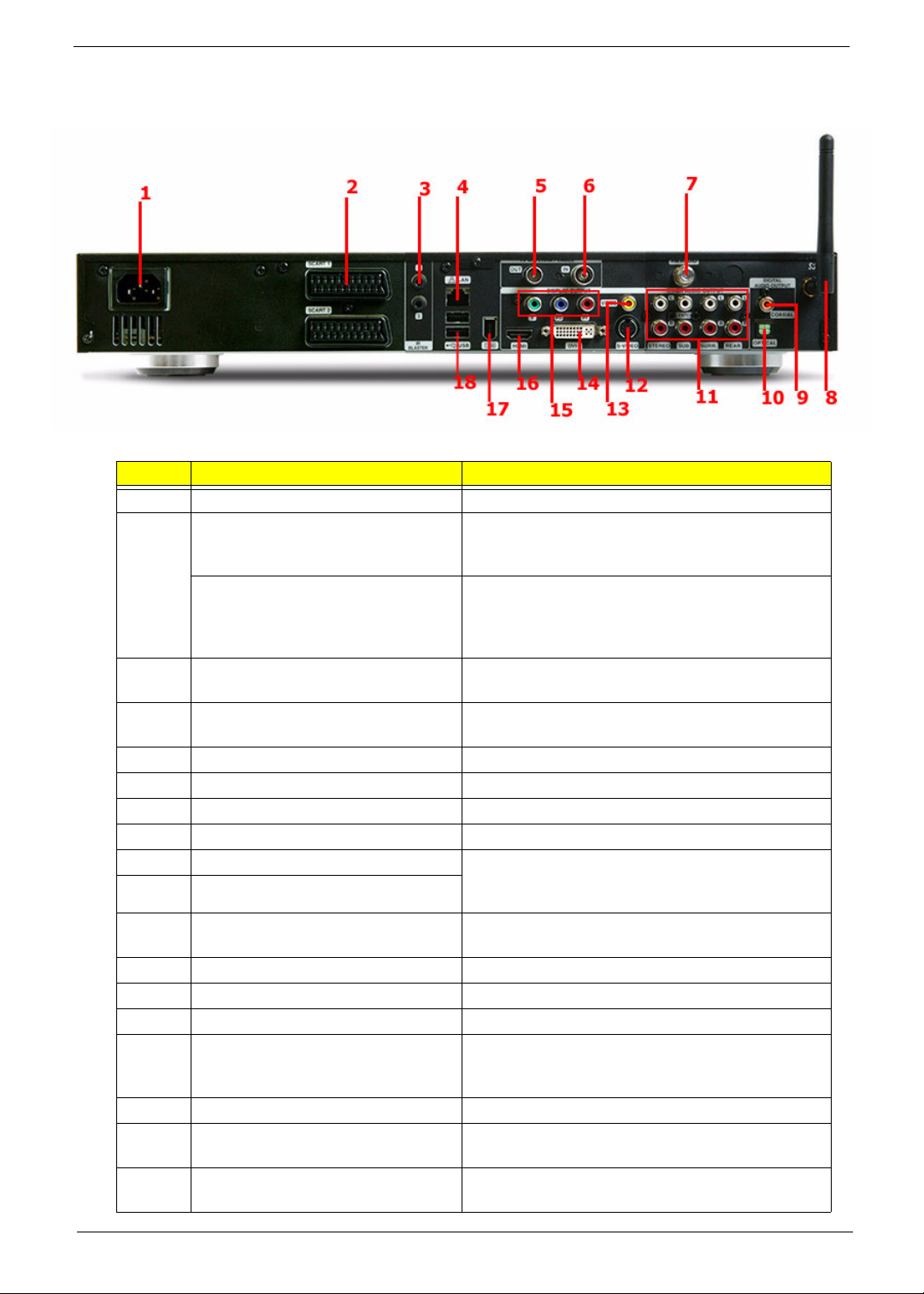
Rear Panel View
No. Component Description
1 Power connector Plug the power cable into this connector.
2 SCART input connector Connects to a set-top box or another A/V device.
SCART input/output connector Connects to a TV or a set-top box. The SCART
3 IR blaster ports Connects an IR blaster to the set-top-box’s IR
4 LAN port Connects to an Ethernet 10/100/1000MB based
5 TV antenna/cable output jack Connects to a television.
6 TV antenna/cable input jack Connects to an antenna or cable TV.
7 FM radio input jack Connects to an external FM radio antenna.
8 WLAN antenna connector Connects to a wireless LAN antenna.
9 Coaxial digital audio output jack Connects to a digital device, such as MiniDisc
10 Optical digital audio output jack
11 Multi-channel speaker audio output
connectors
12 Video output jack Connects to a TV with video output.
13 S-Video output jack Connects to a TV with S-Video input.
14 Component video output jack Connects to a TV with YPbPr input.
15 DVI-I connector Connects to a TV or LCD with DVI input or use the
16 HDMI Connects to a TV with HDMI input.
17 6-pin IEEE 1394 port Connects to an IEEE 1394 device (e.g., digital
18 USB 2.0 ports Connects to USB peripherals devices (e.g., USB
The SCART input connector supports Video, SVideo and Audio (L and R) input signals.
input/output connector supports Video, S-Video,
Audio (L and R) input and Composite Video and
Audio (L and R) output signals.
sensor window.
network
recorders, home theater receivers, or A/V
receivers.
Connects to an amplifier which has multi-channel
audio system.
DVI-to-VGA adapter to connect a TV or monitor
with VGA (D-Sub) input.
video camcorder, hard disk, scanners).
mouse, USB printer, USB drive).
Chapter 1 11
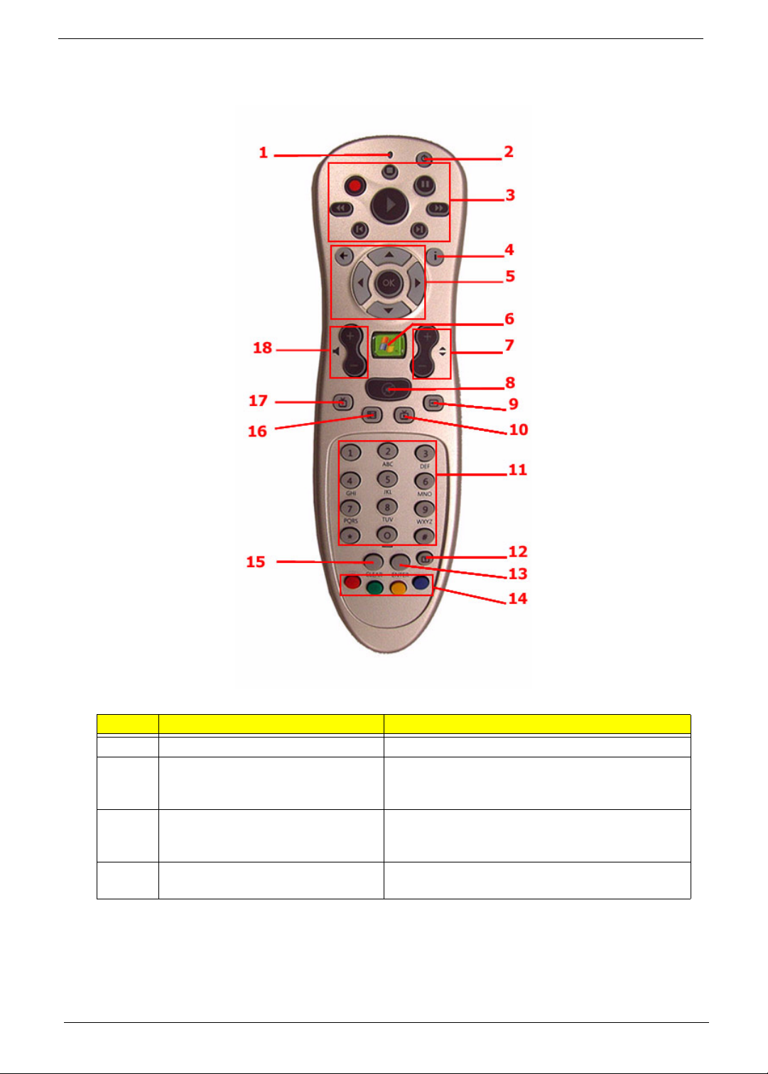
Remote Control
No. Component Description
1 Power LED Indicates that a command button is pressed.
2 Sleep Press to turn system to standby (sleep) mode.
While in standby (sleep) mode, press the button
again to wake up or activate the system.
3 Playback controls Lets you play, record, pause, stop, forward,
rewind, skip or replay a song, slide show, movie or
a TV program.
4 More Info Displays more information regarding the active TV
program, video, album, or pictures.
12 Chapter 1
No. Component Description
5 Navigation buttons The following navigation buttons let you access all
Media Center pages:
• Arrow buttons: navigates through the menu
options.
• OK: selects an option in the Media Center menus
and confirm your selection.
• Back: Moves back to the previous screen.
6 Start Press the Start button to launch the Media Center
Home Page.
7 Channel/Page Moves pages up and down or changes the
channels on the My TV page.
8 Mute Turns the system sound off and on.
9 DVD menu When a DVD video is playing, press this button to
display the DVD disc’s main menu.
10 Live TV Displays a full screen view of a live TV program.
11 Numeric buttons Switches channels or inputs alphanumeric
characters in the Media Center text box.
12 Teletext Turns Teletext on and off.
13 Enter Press to confirm your input or selection.
14 Teletext hotkeys When setting up programs in the TV menu, the
following colored buttons have the following
function:
• Red: navigate to the previous page
• Green: move to the next page
• Yellow and blue: select, insert, and return to the
Teletext menu.
15 Clear Press to erase the character you entered.
16 Guide Opens the TV Program Guide to display available
channels and programs that you can watch and
recorded.
Note: Available in selected country and
regions.
17 Recorded TV Displays the Recorded TV page.
18 Volume control Increases or decreases the volume.
Note: The Teletext function is only available when the TV channel is broadcasting the Teletext programme.
Teletext is a type of information service provided by the television broadcast companies. Teletext allows you to
view the information of a video or program on your display device (i.e., news, weather, stock market, travel,
etc.).
Note: Remote control appearance (shape and buttons) may vary with region and retail configuration.
Using the Remote Control
The Media Center remote control complements the wireless keyboard. It includes control buttons that is commonly
found on a DVD player, VCR or TV. Use the remote control to open the Media Center Edition program and
navigate through menus and commands; to listen to music, watch TV and DVDs, and view pictures and slide
shows.
1. Use the remote control to point towards the system’s IR receiver. Refer to “Front View” for the location of the IR
receiver.
2. Press the button to launch or return to the Media Centre Home Page.
Chapter 1 13
Wireless Keyboard
The wireless keyboard with built-in touch pad combines mouse control with touch typing. It has full-sized keys that
include shortcut keys, status LED, power switch, touch pad, left and right buttons, arrow keys, one Windows key,
left and right mouse keys, and 12 function keys.
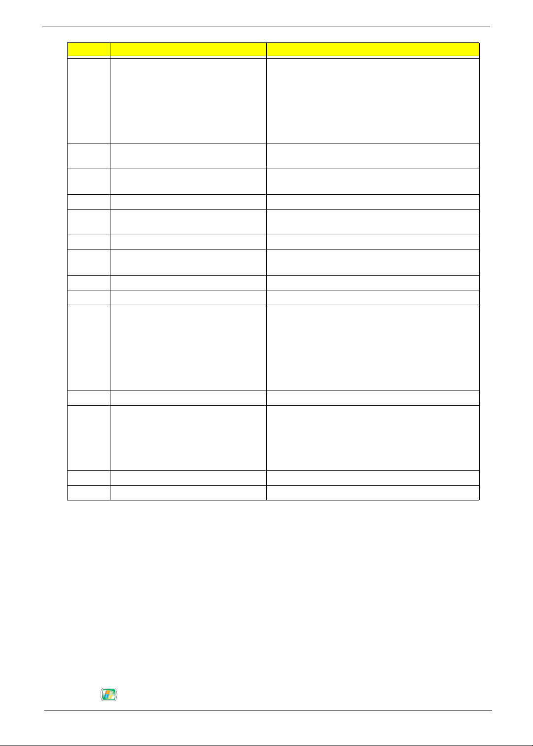
No. Component Description
1 Shortcut keys Use the shortcut keys to do the following:
• A Puts system to standby (sleep) mode.
• B Launches Internet Explorer.
• C Launches Microsoft Outlook Express.
• D Launches Media player.
• E Toggles the Media player sound on or off.
• F Increases or decreases volume.
• G Plays or pauses the Media player.
2 Status LED Displays the following functions:
• Green LED indicates the keyboard is turned on. The
LED will flash for three seconds to confirm it is
powering on, then stops flashing.
• Flashing Green LED indicates the keyboard is
synchronized to the system.
• Red LED indicates battery level is low. The LED will
turn green then flash red for two seconds to indicate
keyboard’s battery level is low.
3 Power switch Turns the keyboard on and off. Slide to the right to turn
on the keyboard or slide to the left to power off the
keyboard.
4 Touch pad Pointing device that senses movement on its surface.
Move your finger on the surface of the touch pad to
move the cursor.
14 Chapter 1
No. Component Description
5 Left and right buttons Press the left and right buttons to select and execute
functions. These two buttons are similar to the left and
right buttons on a mouse. Tapping on the touch pad
produces similar results to clicking the left button.
6 Arrow keys Moves the pointer around the Media Center menus.
7 Windows logo key Start button. Combinations with this key perform
special functions, such as:
• + Tab: Activate the next Taskbar button.
• + E: Explore My Computer.
• + F: Find Document.
• + M: Minimize All.
• Shift + + M: Undo Minimize All.
• + R: Display Run dialog box.
8 Left and right mouse keys Press to simulate left and right mouse clicks.
9 Function keys (F1 to F12) The function keys lets you perform specific functions,
depending on the application that uses them.
Note: The keyboard may vary depending on region.
Chapter 1 15
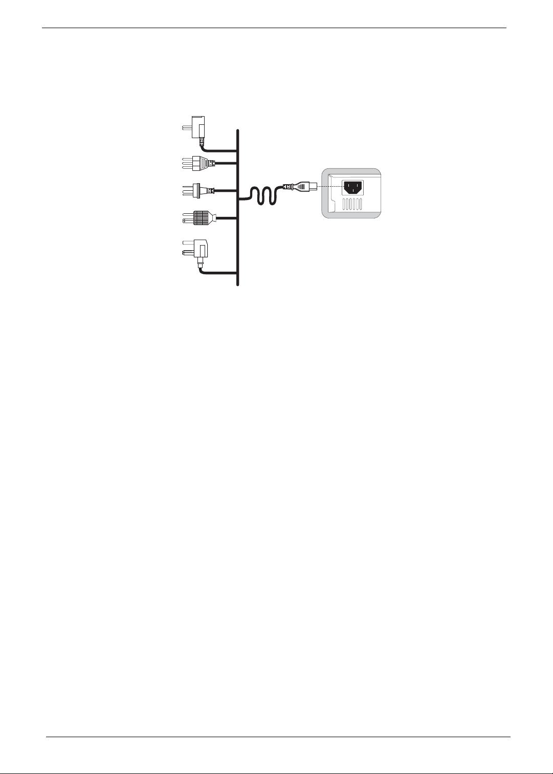
Setting up the System
Connecting the Power Cable
Note: Please use the corresponding power cord for your region.
16 Chapter 1
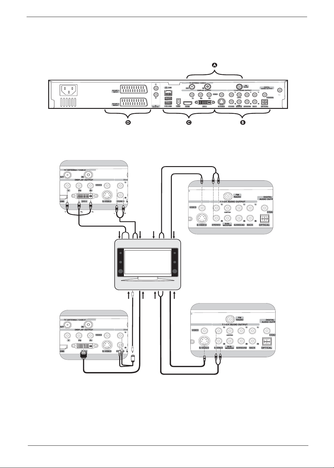
Connecting Display Devices
Please refer to the illustrations below for the possible and recommended connection type for setting up your
display device.
Component (YPbPr) + stereo audio Video + stereo audio
A
B
B
A
DVI + stereo audio* S-video + stereo audio
Note: *Please use an extension cable to connect the Y cable to the display device’s speaker input.
Chapter 1 17
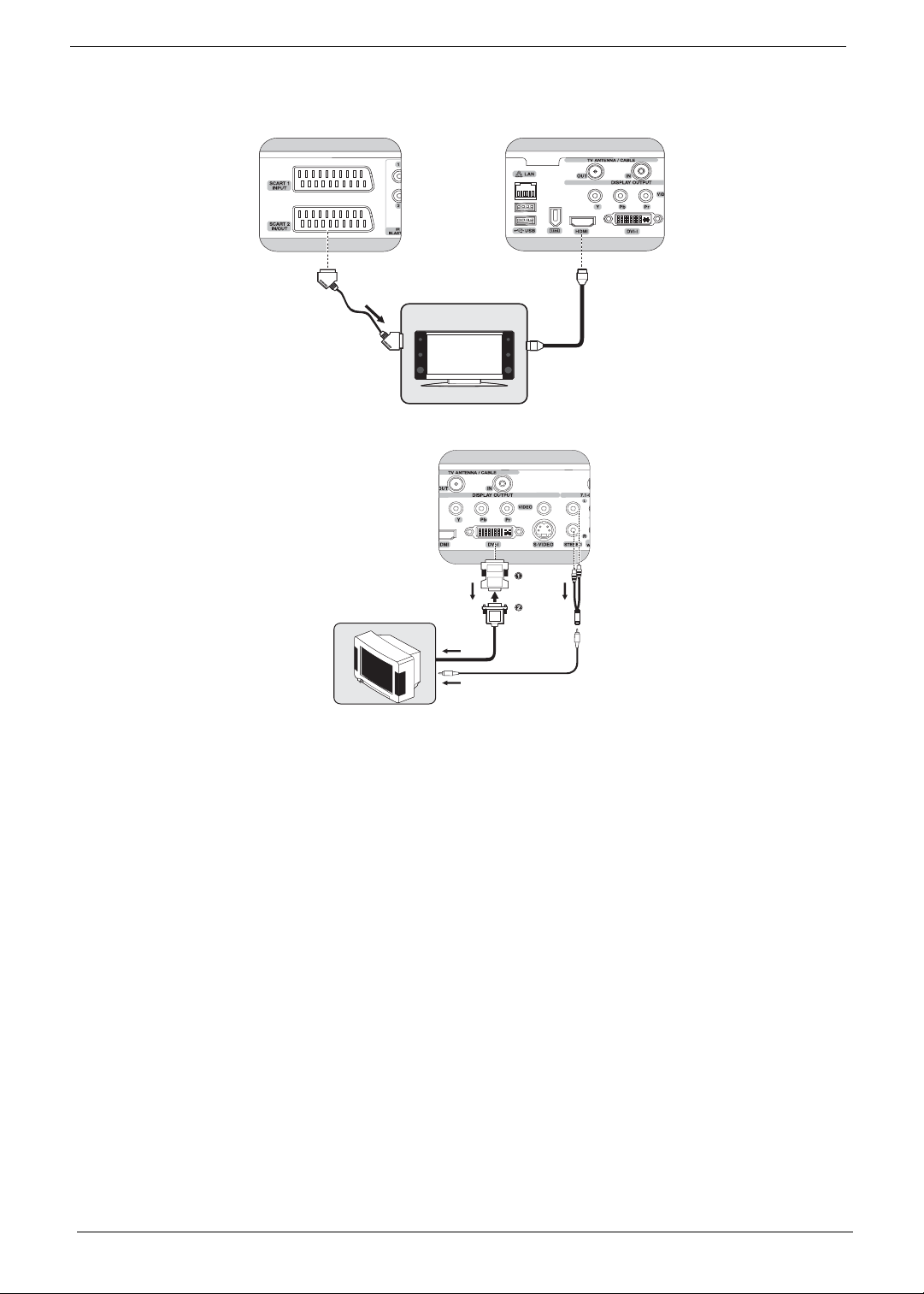
SCART* HDMI
D
DVI to VGA using converter + stereo audio
C
A
Note: Overscaling is a normal behavior on most TVs. We recommend using a TV that supports VGA or DVI
connector, or enabling the dot-by-dot feature on your TV when connected with HDMI.
18 Chapter 1
Loading...