


ARMC-3P
ARMC/3P
User Guide
Release 04.02.00
Copyright © 2007 Acer Inc
Userguide_ARMC/3P_v2
March 2007
100-80-8250-00


Copyright and Trademark Information
This document contains proprietary information that is protected by copyright. All rights
reserved. No part of this document may be photocopied, reproduced, or translated into
another language without express prior written consent of Acer Inc.
© Copyright 2007 Acer Inc, All rights reserved. Java is a registered trademark of Sun
Microsystems, Inc. Internet Explorer is a registered trademark of Microsoft Corporation.
Netscape and Netscape Navigator are registered trademarks of Netscape
Communication Corporation. The Raritan logo are trademarks of Raritan Computer, Inc.
All other marks are the property of their respective owners.
FCC Information
This equipment has been tested and found to comply with the limits for a Class A digital
device, pursuant to Part 15 of the FCC Rules. These limits are designed to provide
reasonable protection against harmful interference in a commercial installation. This
equipment generates, uses, and can radiate radio frequency energy and if not installed
and used in accordance with the instructions, may cause harmful interference to radio
communications. Operation of this equipment in a residential environment may cause
harmful interference.
Japanese Approvals
Acer is not responsible for damage to this product resulting from accident, disaster,
misuse, abuse, non-Acer modification of the product, or other events outside of Acer’s
reasonable control or not arising under normal operating conditions.
LISTED
C
US
L
U
1F6 1
I.T.E .
For assistance around the world, please see the back cover of this guide for
regional Acer Inc contact information.

Safety Guidelines
To avoid potentially fatal shock hazard and possible damage to Acer equipment:
• Test AC outlets at your computer and monitor for proper polarity and grounding.
• Use only with grounded outlets at both the computer and monitor. When using a
backup UPS, power the computer, monitor and appliance off the supply.

C
ONTENTS
i
Contents
ARMC/3P
ARMC/3PARMC/3P
ARMC/3P ................................
................................................................
................................................................
................................................................
........................................................
................................................
........................ 1
11
1
Contents
ContentsContents
Contents ................................
................................................................
................................................................
................................................................
.........................................................
..................................................
......................... i
ii
i
Figures
FiguresFigures
Figures................................
................................................................
................................................................
................................................................
...........................................................
......................................................
...........................iv
iviv
iv
Tables
TablesTables
Tables................................
................................................................
................................................................
................................................................
............................................................
........................................................
............................vi
vivi
vi
Chapter 1: Introduction
Chapter 1: IntroductionChapter 1: Introduction
Chapter 1: Introduction ................................
................................................................
................................................................
................................................................
.................................
..
. 1
11
1
Product Overview ......................................................................................................1
Product Photos..........................................................................................................1
Product Features.......................................................................................................3
Terminology............................................................................................................... 3
Package Contents .....................................................................................................5
When the Server is up and running ........................................................................... 5
When the Server is dead ...........................................................................................6
Chapter 2: Installation
Chapter 2: InstallationChapter 2: Installation
Chapter 2: Installation ................................
................................................................
................................................................
................................................................
..................................
....
.. 7
77
7
Operation Overview................................................................................................... 7
Connectors and Jumpers........................................................................................... 7
Serial Interface...................................................................................................................................8
USB Plug ...........................................................................................................................................8
Video/USB System Interface .............................................................................................................8
10/100 Mpbs Ethernet Adaptor..........................................................................................................8
External Power Option.......................................................................................................................8
Power using ATX Power Cable Adaptor ............................................................................................8
ATX Power Reset ..............................................................................................................................8
Intelligent Management Platform Bus Connector (IPMB) ..................................................................9
The Set to Default (S2D) Pins ...........................................................................................................9
Serial 1, Serial 2 and PS/2.................................................................................................................9
Placing the ARMC/3P into the Server...................................................................... 11
Open the Server ..............................................................................................................................11
Plugging an ARMC/3P into a PCI Slot .............................................................................................11
Chapter 3: Configuration
Chapter 3: ConfigurationChapter 3: Configuration
Chapter 3: Configuration ................................
................................................................
.............................................................
..........................................................
............................. 17
1717
17
Initial Configuration.................................................................................................. 17
ARMC/3P Psetup Tool ............................................................................................ 17
Using the Psetup Tool via Graphical User Interface ........................................................................17
Running the Linux Psetup Tool via Command Line .........................................................................18
Mac Address Detection ........................................................................................... 20
Authentication.......................................................................................................... 20
Initial Configuration via DHCP Server...................................................................... 21
Initial Configuration via Serial Console ....................................................................21
Web Interface..........................................................................................................22
Mouse, Keyboard and Video configuration ..............................................................22
ARMC/3P USB interface..................................................................................................................22
ARMC/3P Keyboard Settings ..........................................................................................................23
Remote Mouse Settings ..................................................................................................................23
Auto Mouse Speed and Mouse Synchronization .............................................................................23
Host System Mouse Settings...........................................................................................................24
Single and Double Mouse Mode......................................................................................................25
Recommended Mouse Settings.......................................................................................................25
Video Modes....................................................................................................................................26
Resetting the ARMC/3P to its Factory Settings........................................................ 26
Using the S2D Pins..........................................................................................................................26
Using the Serial Interface ................................................................................................................26

ii C
ONTENTS
Chapter 4: Usage
Chapter 4: UsageChapter 4: Usage
Chapter 4: Usage................................
................................................................
................................................................
................................................................
.........................................
..................
......... 27
2727
27
Prerequisites ........................................................................................................... 27
HTTP/HTTPS ..................................................................................................................................27
Telnet...............................................................................................................................................27
SSH .................................................................................................................................................27
Login into the ARMC/3P and logout.........................................................................28
Login into the ARMC/3P ..................................................................................................................28
Navigation........................................................................................................................................29
Logout from the ARMC/3P...............................................................................................................31
Managing the ARMC/3P with a CommandCenter....................................................31
The Remote Console...............................................................................................31
General Description .........................................................................................................................31
Main Window ...................................................................................................................................32
Remote Console Control Bar...........................................................................................................33
Remote Console Options.................................................................................................................34
Remote Console Status Line ...........................................................................................................44
Optimizing the Video Picture ...........................................................................................................45
Reducing the Noise of the Video Picture .........................................................................................46
Using the ARMC/3P with low bandwidth..........................................................................................47
Chapter 5: Menu Options
Chapter 5: Menu OptionsChapter 5: Menu Options
Chapter 5: Menu Options................................
................................................................
.............................................................
..........................................................
............................. 49
4949
49
Remote Control ....................................................................................................... 49
KVM Console...................................................................................................................................49
Remote Power.................................................................................................................................49
Telnet Console.................................................................................................................................51
Virtual Media ........................................................................................................... 54
Floppy Disk......................................................................................................................................54
CD ROM ..........................................................................................................................................55
Drive Redirection .............................................................................................................................59
Options ............................................................................................................................................62
Creating an Image ...........................................................................................................................63
System Health.........................................................................................................65
Chassis Control ...............................................................................................................................65
Monitor Sensors...............................................................................................................................65
System Event Log............................................................................................................................66
Alarm Settings .................................................................................................................................66
User Management................................................................................................... 67
Change Password ...........................................................................................................................67
User and Groups .............................................................................................................................67
Permissions .....................................................................................................................................69
KVM Settings........................................................................................................... 70
User Console...................................................................................................................................70
Power Control..................................................................................................................................73
Keyboard/Mouse..............................................................................................................................74
Video ...............................................................................................................................................75
Device Settings .......................................................................................................78
Network ...........................................................................................................................................78
Dynamic DNS ..................................................................................................................................81
Security............................................................................................................................................83
Certificate ........................................................................................................................................86
Serial Port........................................................................................................................................89
Intelligent Platform Management Interface (IPMI)............................................................................92
Date/Time ........................................................................................................................................93
Authentication..................................................................................................................................93
Event Log ........................................................................................................................................96
SNMP Settings ................................................................................................................................98
Maintenance.......................................................................................................... 101
Device Information.........................................................................................................................101
Language.......................................................................................................................................102
Event Log ......................................................................................................................................103
Update Firmware ...........................................................................................................................103
Unit Reset......................................................................................................................................104
Appendix A: Specifications
Appendix A: SpecificationsAppendix A: Specifications
Appendix A: Specifications ................................
................................................................
........................................................
................................................
........................105
105105
105
Sizes and Weights................................................................................................. 105
Environment .......................................................................................................... 105
Temperature ..................................................................................................................................105

C
ONTENTS
iii
Humidity.........................................................................................................................................105
Appendix B: ARMC/3P Video Modes
Appendix B: ARMC/3P Video ModesAppendix B: ARMC/3P Video Modes
Appendix B: ARMC/3P Video Modes ................................
................................................................
...........................................
......................
...........107
107107
107
Appendix C: Key Codes
Appendix C: Key CodesAppendix C: Key Codes
Appendix C: Key Codes ................................
................................................................
..............................................................
............................................................
..............................109
109109
109
Appendix D: Pin Assignment
Appendix D: Pin AssignmentAppendix D: Pin Assignment
Appendix D: Pin Assignment ................................
................................................................
......................................................
............................................
......................111
111111
111
VGA HD-15 ........................................................................................................... 111
RJ45 Connetcor Ethernet ...................................................................................... 111
IPMB/I2 Connector ................................................................................................ 111
Serial SUB-D9 Connector 1...................................................................................112
PS/2 Connector..................................................................................................... 112
USB....................................................................................................................... 112
Appendix E: Troub
Appendix E: TroubAppendix E: Troub
Appendix E: Troubleshooting
leshootingleshooting
leshooting ................................
................................................................
.....................................................
..........................................
.....................113
113113
113
Appendix F: GNU General Public License (GPL)
Appendix F: GNU General Public License (GPL)Appendix F: GNU General Public License (GPL)
Appendix F: GNU General Public License (GPL) ........................
................................................
........................115
115115
115
Appendix G: The OpenLADAP Public License
Appendix G: The OpenLADAP Public LicenseAppendix G: The OpenLADAP Public License
Appendix G: The OpenLADAP Public License ............................
........................................................
............................121
121121
121

iv F
IGURES
Figures
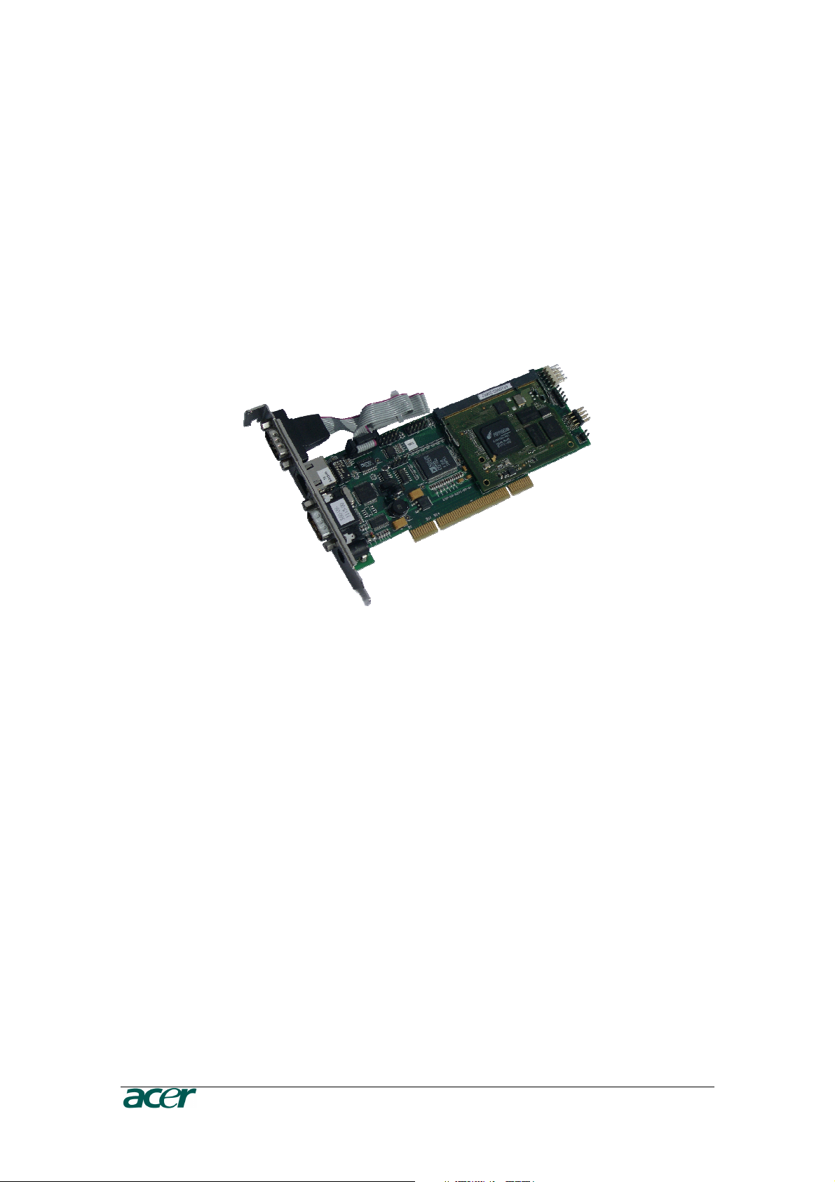
Figure 1 ARMC/3P with High-Profil Bracket................................................................................................. 1
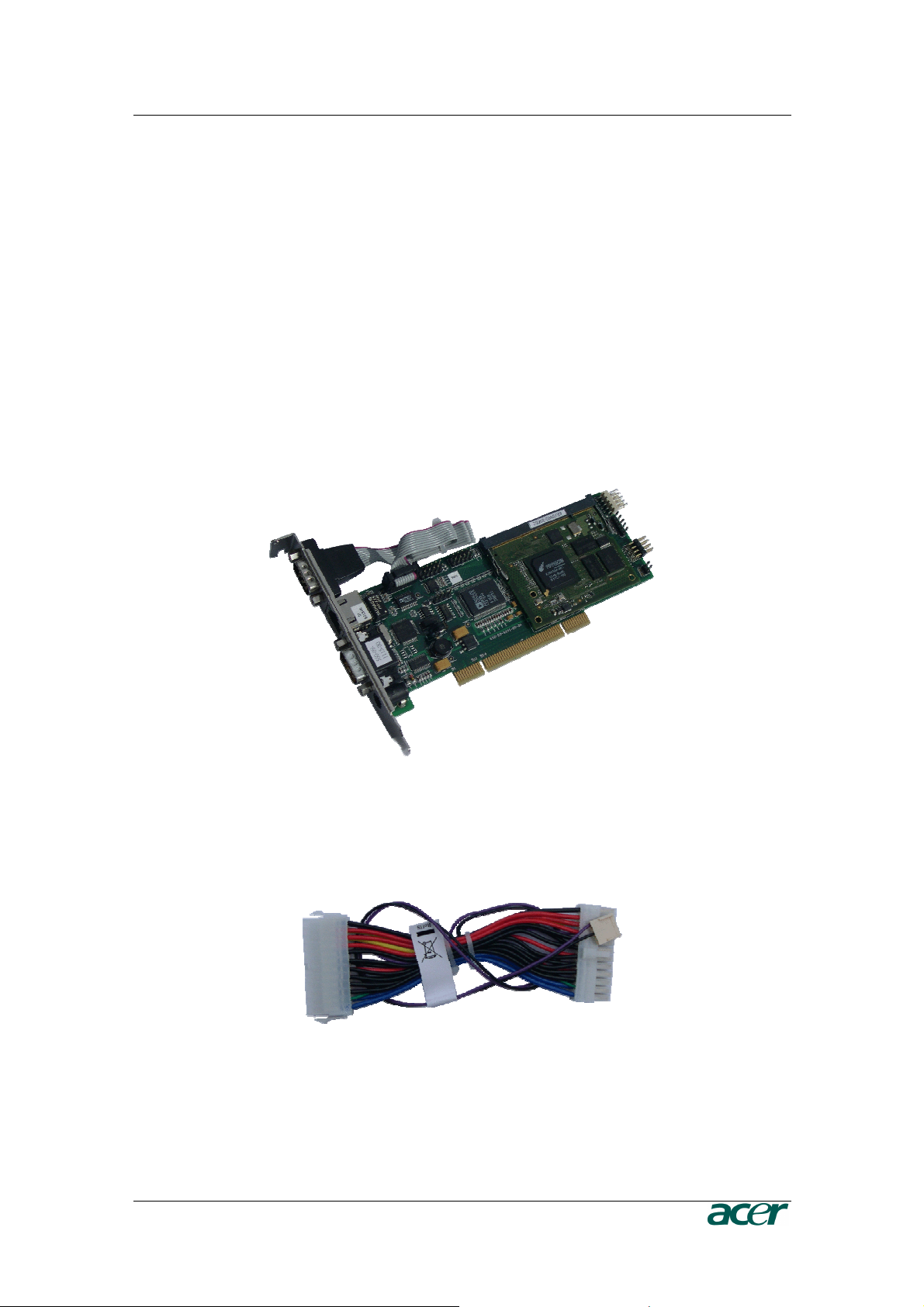
Figure 2 24-pole ATX Power Cable Adaptor ................................................................................................ 1
Figure 3 ARMC/3P with Low-Profil Bracket.................................................................................................. 2
Figure 4 IPMB Cable, Power Cable, Reset Cable........................................................................................ 2
Figure 5 Serial Cable ................................................................................................................................... 2
Figure 6 VGA-USB System Cable and PS/2 System Cable......................................................................... 2
Figure 7 ARMC/3P Internal Connectors....................................................................................................... 7
Figure 8 Connection of the ARMC/3P VGA-USB System Cable.................................................................. 7
Figure 9 ARMC/3P Reset/Power Connection Pinout ................................................................................... 9
Figure 10 ARMC/3P with PS/2................................................................................................................... 10
Figure 11 PS/2 System Cable.................................................................................................................... 10
Figure 12 Mounting the ARMC/3P into a PCI Slot ..................................................................................... 11
Figure 13 IPMB Cable................................................................................................................................ 11
Figure 14 IPMB Connector......................................................................................................................... 12
Figure 15 Power using Reset/Power Wires................................................................................................ 12
Figure 16 Power using ATX Power Cable Adaptor .................................................................................... 14
Figure 17 ARMC/3P Psetup Tool (Windows Version)................................................................................ 18
Figure 18 ARMC/3P Psetup Tool (Linux Version)...................................................................................... 18
Figure 19 Remote Console Control Bar: Sync Button................................................................................ 24
Figure 20 Terminal with Reset Message.................................................................................................... 26
Figure 21 The Internet Explorer displaying the Encryption Key Length ..................................................... 28
Figure 22 Login Screen.............................................................................................................................. 28
Figure 23 Password Change Request ....................................................................................................... 29
Figure 24 ARMC/3P Main Page Overview ................................................................................................. 30
Figure 25 Navigation Frame Overview....................................................................................................... 30
Figure 26 Logout Link ................................................................................................................................ 31
Figure 27 Remote Console ........................................................................................................................ 32
Figure 28 Remote Console Control Bar ..................................................................................................... 33
Figure 29 Remote Console Options Menu ................................................................................................. 34
Figure 30 Remote Console Options Menu: Scaling ................................................................................... 35
Figure 31 Remote Console Options Menu: Mouse Handling ..................................................................... 36
Figure 32 Remote Console Options Menu: Local Cursor........................................................................... 37
Figure 33 Remote Console Options Menu: Chat Window.......................................................................... 37
Figure 34 Remote Console Options Menu: Video Settings Panel.............................................................. 39
Figure 35 Remote Console Options Menu: Softkeyboard.......................................................................... 41
Figure 36 Soft Keyboard Mapping ............................................................................................................. 41
Figure 37 Remote Console Options Menu: Hotkey Confirmations Dialog.................................................. 42
Figure 38 Remote Console Options Menu: Encoding - Predefined............................................................ 42
Figure 39 Remote Console Options Menu: Encoding - Compression........................................................ 43
Figure 40 Remote Console Options Menu: Encoding – Color Depth ......................................................... 44
Figure 41 Remote Console Status Line ..................................................................................................... 44
Figure 42 Status Line Transfer Rate .......................................................................................................... 45
Figure 43 Remote Console Video Settings: Reset this Mode .................................................................... 46
Figure 44 Main Page with Remote Console Preview ................................................................................. 49
Figure 45 Power Control Overview ............................................................................................................ 50
Figure 46 ‘Internal Power Control’ Buttons................................................................................................. 50
Figure 47 ‘Power Control via IPMI’ Buttons................................................................................................ 51
Figure 48 Telnet Console........................................................................................................................... 52
Figure 49 Floppy Virtual Area .................................................................................................................... 54
Figure 50 Select Image File ....................................................................................................................... 55
Figure 51 Active Image File ....................................................................................................................... 55

F
IGURES
v
Figure 52 Selecting CD-ROM and Windows Share ................................................................................... 56
Figure 53 The Image File on the Share...................................................................................................... 57
Figure 54 Explorer Context Menu .............................................................................................................. 58
Figure 55 Share Configuration Dialog........................................................................................................ 58
Figure 56 Drive Redirection ....................................................................................................................... 59
Figure 57 Main View .................................................................................................................................. 60
Figure 58 Selecting the desired Drive ........................................................................................................ 61
Figure 59 Selection Write Support ............................................................................................................. 61
Figure 60 Device Authentification .............................................................................................................. 61
Figure 61 Virtual Drive Selection................................................................................................................ 62
Figure 62 Tray Info..................................................................................................................................... 62
Figure 63 USB Mass Storage Option......................................................................................................... 62
Figure 64 RawWrite for Windows Selection Dialog.................................................................................... 63
Figure 65 Nero Selection Dialog ................................................................................................................ 64
Figure 66 Chassis Control.......................................................................................................................... 65
Figure 67 Monitor Sensors Overview......................................................................................................... 66
Figure 68 System Event Log Overview...................................................................................................... 66
Figure 69 IPMI Alarm Configuration........................................................................................................... 66
Figure 70 Set Password............................................................................................................................. 67
Figure 71 User/Group Management .......................................................................................................... 67
Figure 72 User/Group Permission Settings................................................................................................ 69
Figure 73 User Console Settings (Part 1) .................................................................................................. 70
Figure 74 User Console Settings (Part 2) .................................................................................................. 71
Figure 75 Power Control ............................................................................................................................ 73
Figure 76 Keyboard and Mouse Settings................................................................................................... 74
Figure 77 Video Settings............................................................................................................................ 77
Figure 78 Network Settings........................................................................................................................ 78
Figure 79 Dynamic DNS ............................................................................................................................ 81
Figure 80 Dynamic DNS Scenario ............................................................................................................. 81
Figure 81 Security Settings ........................................................................................................................ 83
Figure 82 Certificate Settings..................................................................................................................... 87
Figure 83 SSL Certificate Upload............................................................................................................... 88
Figure 84 Serial Settings............................................................................................................................ 90
Figure 85 IPMI Settings.............................................................................................................................. 92
Figure 86 Date and Time ........................................................................................................................... 93
Figure 87 Authentication Settings .............................................................................................................. 95
Figure 88 Event Log Settings..................................................................................................................... 97
Figure 89 SNMP Settings........................................................................................................................... 99
Figure 90 Device Information ................................................................................................................... 101
Figure 91 Connected Users ..................................................................................................................... 101
Figure 92 Voltages Overview ................................................................................................................... 102
Figure 93 Language Settings ................................................................................................................... 102
Figure 94 Event Log List .......................................................................................................................... 103
Figure 95 Update Firmware Dialog .......................................................................................................... 103
Figure 96 Unit Reset ................................................................................................................................ 105
Figure 97 English (US) keyboard Layout, used for the key codes ........................................................... 109
Figure 98 VGA HD-15.............................................................................................................................. 111
Figure 99 RJ45 ........................................................................................................................................ 111
Figure 100 Serial Connector .................................................................................................................... 112

vi F
IGURES
Tables
Table 1 Hardware Failures........................................................................................................................... 6
Table 2 Host System Failures and how they are detected........................................................................... 6
Table 3 Voltage and Power Specification................................................................................................... 14
Table 4 Initial Network Configuration ......................................................................................................... 17
Table 5 Serial Line Parameters.................................................................................................................. 21
Table 6 Standard User Settings ................................................................................................................. 22
Table 7 Standard User Settings ................................................................................................................. 29
Table 9 Links for Navigation....................................................................................................................... 30
Table 10 Buttons displaying the Access Status ......................................................................................... 45
Table 11 Buttons displaying the Monitor State........................................................................................... 45
Table 12 ARMC/3P Specifications ........................................................................................................... 105
Table 13 Temperature ............................................................................................................................. 105
Table 14 Humidity .................................................................................................................................... 105
Table 15 ARMC/3P Video Modes ............................................................................................................ 107
Table 16 Key Names ............................................................................................................................... 109
Table 17 VGA HD-15 ............................................................................................................................... 111
Table 18 RJ45.......................................................................................................................................... 111
Table 19 IPMB/I2C Connector ................................................................................................................. 111
Table 20 Serial Connector 1 .................................................................................................................... 112
Table 21 Serial Connetcor 2 .................................................................................................................... 112
Table 22 PS/2 Connector......................................................................................................................... 112
Table 23 USB Connector ......................................................................................................................... 112

F
IGURES
vii

C
HAPTER
1:
I
NTRODUCTION
1
Chapter 1: Introduction
Product Overview
The ARMC/3P is a manufacturer-independent remote administration system. The
ARMC/3P works as an integrated solution on your server system. Based on an
embedded operating system, the ARMC/3P provides both exceptional stability and
permanent availability independent of the present state of the server’s operating system.
As a system administrator, you have entire control and location-independent remote
access to react upon both critical incidents and cases of necessary maintenance.
Product Photos
Figure 1 ARMC/3P with High-Profil Bracket
Figure 2 24-pole ATX Power Cable Adaptor

2 P
RODUCT
U
SER
G
UIDE
Figure 3 ARMC/3P with Low-Profil Bracket
Figure 4 IPMB Cable, Power Cable, Reset Cable
Figure 5 Serial Cable
Figure 6 VGA-USB System Cable and PS/2 System Cable

C
HAPTER
1:
I
NTRODUCTION
3
Product Features
The ARMC/3P defines a new class of remote access devices. It combines digital remote
access via IP networks with comprehensive and integrated system management. The
ARMC/3P offers convenient, remote KVM access and control via LAN or Internet. It
captures, digitizes, and compresses video and transmits it with keyboard and mouse
signals to and from a remote computer. Remote access and control software runs on its
embedded processors only, but not on mission critical servers, so there is no
interference with server operation or impact on network performance.
Furthermore, the ARMC/3P offers additional remote power management with the help of
optional available devices. Features of the ARMC/3P are:
- KVM (keyboard, video, mouse) access over IP or telephone line
- No impact on server or network performance
- Automatically senses video resolution for best possible screen capture
- High-performance mouse tracking and synchronization
- Port to connect a user console for direct analogous access to KVM device
- Local mouse suppression (only when using SUN’s Java Virtual Machine)
- Remote Power Management
- Remote Virtual Media
Terminology
ACPI
Advanced Configuration and Power Interface
A specification that enables the operating system to implement power
management and system configuration.
ATX
Advanced Technology Extended
A specification that covers the style of motherboards and enclosures
introduced by Intel in 1995.
Client
The workstation of the user for connecting the host system through the
ARMC/3P.
DHCP
Dynamic Host Configuration Protocol
A protocol for dynamically assigning IP addresses to host names,
especially used in a local network.
DNS
Domain Name System
A protocol used to locate computers on the Internet by their name.
FAQ
Frequently Asked Questions

4 P
RODUCT
U
SER
G
UIDE
Host
Host System
The server system which is hosting the ARMC/3P.
HTTP
Hypertext Transfer Protocol
One of the protocols used for communication between single computers,
especially between web browsers and web servers.
HTTPS
Hypertext Transfer Protocol Secure
The secure version of HTTP.
IPMI
Intelligent Platform Management Interface
A specification defining a set of common interfaces for operating system
independent platform management and health monitoring.
LED
Light Emitting Diode
A semiconductor device that emits incoherent monochromatic light when
electrically biased in the forward direction.
PS/2
Personal System/2
IBM’s second generation of personal computers, which was released to
the public in 1987. Today, PS/2 is known as a device interface for mouse
and keyboard.
SNMP
Simple Network Management Protocol
A widely used network monitoring and control protocol.
SSH
Secure Shell
An encrypted network protocol providing a secure replacement for Telnet.
SSL
Secure Socket Layer
An encryption technology for the Internet used to provide secured data
transmissions.
SVGA
Super Video Graphics Array
A refinement of the Video Graphics Array (VGA) that provides increased
pitch and resolution performance.
UTP
Unshielded Twisted Pair
A cable with two conductors twisted as a pair and bundled within the
same outer PVC covering.

C
HAPTER
1:
I
NTRODUCTION
5
Package Contents
The ARMC/3P comes as a regular PCI card and is shipped with:
- an ARMC/3P Board with High-Profile Bracket
- a VGA-USB System Cable
- an IPMB Cable
- an ATX Reset/Switch Cable
- a Videosplitter cable for Local Console
- a CD ROM with User Manual and utilities
- a Quick Start Guide
- an External Power supply # TZ.30400.006
1
1. In EMEA Region the ARMC/3P card is shipped by default with the External Power
Adaptor, In order to make the ARMC/3P card System independent. In other regions it is
an optional item.
Available separately (optional):
- Power Pack US (PWRPK-US-5mm) # TZ.30400.004
External Power Supply
AC Power Cord US
- Power Pack UK (PWRPK-UK-5mm) # TZ.30400.005
External Power Supply
AC Power Cord UK
- Power Pack EU (PWRPK-EU-5mm) # TZ.30400.006
External Power Supply
AC Power Cord EU
When the Server is up and running
The ARMC/3P gives you full control over the remote server. The Management Console
allows you to access the remote server’s graphics, keyboard and mouse and to send
special commands to the server. You can also perform periodic maintenance of the
server. Using the Console Redirection Service you can do the following:
• Reboot the system (a graceful shutdown)
• Watch the boot process
• Boot the system from a separate partition or from Virtual Media
to load the diagnostic environment or install operating systems
• Run special diagnostic programs

6 P
RODUCT
U
SER
G
UIDE
When the Server is dead
Obviously, fixing hardware defects is not possible using a remote management device.
Nevertheless, the ARMC/3P gives the administrator valuable information about the type
of a hardware failure. Serious hardware failures can be categorized into five different
categories with different chances to happen
1
:
Table 1 Hardware Failures
Category Probability
Hard disk failure 50 %
Power cable detached, power supply failure 28 %
CPU, Controller, motherboard failure 10 %
CPU fan failure 8 %
RAM failure 4 %
Using the ARMC/3P,
administrators
can
determine
which
kind
of
serious
har
dwar
e
failur
e
has
occurr
ed
(see
Table 2
).
Table 2 Host System Failures and how they are detected
Category Probability
Hard disk failure Console screen, CMOS set-up
information
Power cable detached, power supply
failure
Server remeians in power off state after
power on command has been given.
CPU, Controller, motherboard failure Power supply is on, but there is no video
putput.
CPU fan failure By IPMI or server specific management
software
RAM failure Boot-Sequence on boot console
Note:
Accor
ding
to
a
survey
made
by
the
Intel
Corp.
C
HAPTER
2:
I
NSTALLATION
7
Chapter 2: Installation
Operation Overview
The ARMC/3P redirects local keyboard, mouse and video data to a remote
administration console. All data is transmitted with the TCP/IP protocol family.
The ARMC/3P can be used in both a multi-administrator and multi-server environments.
Combining one or more ARMC/3P with a single KVM switch allows acess to multiple
servers on a single remote console.
Connectors and Jumpers
Figure 7 and Figure 8 show all connectors and plugs of the ARMC/3P. Each of these
connectors will be explained in the following.
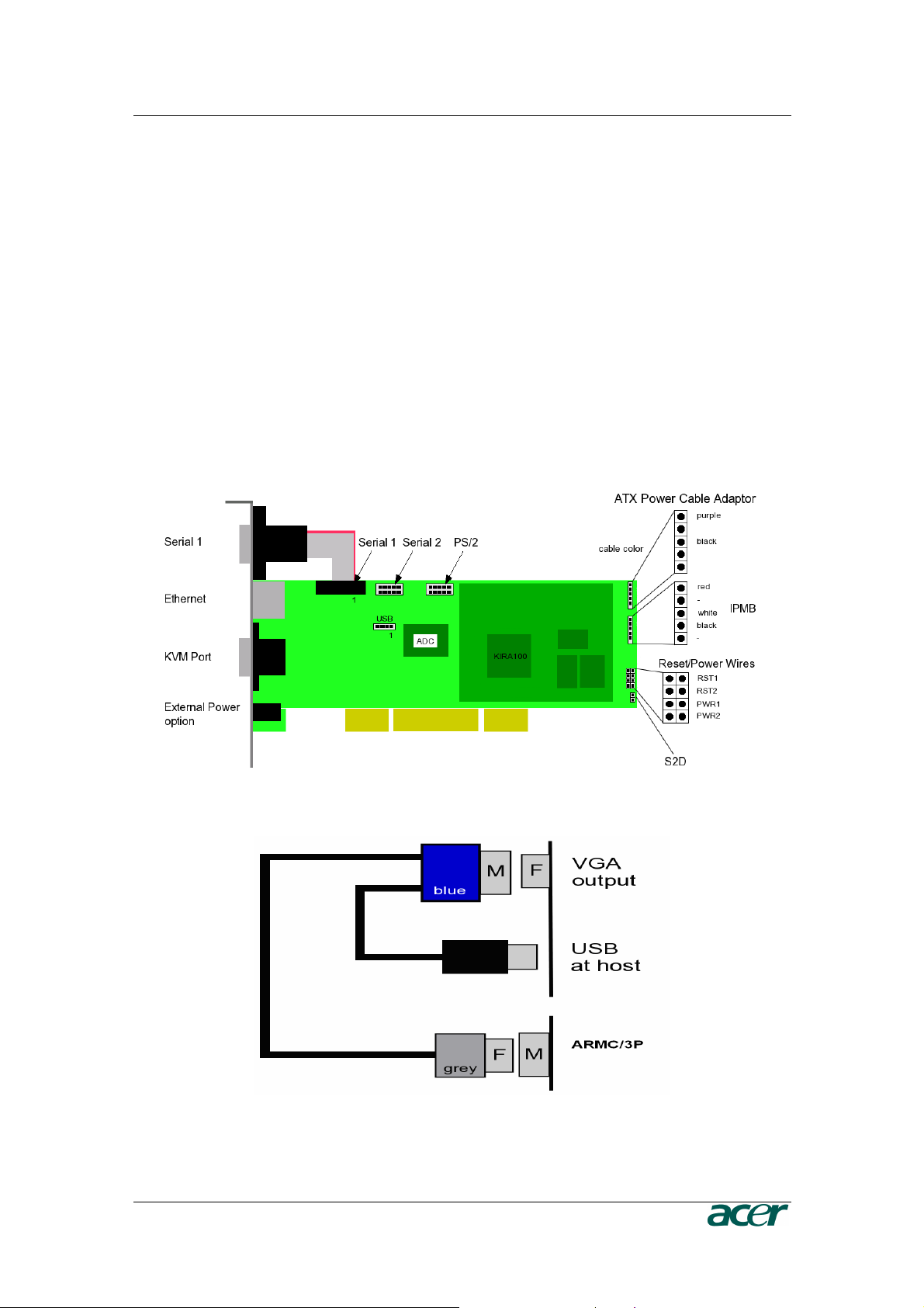
Figure 7 ARMC/3P Internal Connectors
Figure 8 Connection of the ARMC/3P VGA-USB System Cable

8 P
RODUCT
U
SER
G
UIDE
Serial Interface
An optional external modem may be connected to the ARMC/3P using this
connector. The connector is compliant to the RS 232 serial line standard with
hardware handshake.
Every off-the-shelf modem can be connected to the ARMC/3P via the RS 232
interface. For details on configuring and using the serial interface please see
Chapter 5: Serial Port.
USB Plug
Use this connector to connect the ARMC/3P with the host’s USB interface.
Video/USB System Interface
This interface combines both the USB and the Video input connector of the
ARMC/3P. Please connect the supplied system cable to the connector, only.
10/100 Mpbs Ethernet Adaptor
UTP Cat 3 or 5 cables can be connected to the ARMC/3P using a standard RJ45
jack. Refer to Appendix F for the details of the pin assignment for the RJ45
connector.
External Power Option
To allow the ARMC/3P to operate independently from the server system, An
external power supply must be connected to the ARMC/3P. Please see Chapter 2:
Connecting Optional External Power Supply for further details.
Power using ATX Power Cable Adaptor
The 20–pole or 24-pole ATX Power Cable Adaptor has to be connected to the
ARMC/3P and between the motherboard and the host power supply for the internal
powering of the ARMC/3P. Please see Chapter 2: Connecting Power using ATX
Power Cable Adaptor for further details.
ATX Power Reset
Additional cables are required in order to enable the remote reset and the remote
power functions of the ARMC/3P. The reset/power switch has the pin assignment
as shown in Figure 9. Please see Chapter 2: Connecting to ATX Control
Signals for further details.

C
HAPTER
2:
I
NSTALLATION
9
Figure 9 ARMC/3P Reset/Power Connection Pinout
Note: On the ARMC/3P the pin for the power connector is tagged with “ATX”.
Intelligent Management Platform Bus Connector (IPMB)
The IPMB connector on an IPMI capable motherboard allows direct access to
power control functions. Connecting the IPMB connector of the ARMC/3P with
such a port using our IPMB cable makes it possible to use the IPMI over IPMB
function of the ARMC/3P. Refer to Appendix D: Pin Assignment for the pin
assignment details of the IPMB connector.
The Set to Default (S2D) Pins
These pins may be used to reset the ARMC/3P to its factory settings. See Chapter
3: Resetting the ARMC/3P to its Factory Settings for a detailed description on
how to reset the ARMC/3P.
Serial 1, Serial 2 and PS/2
If your server does not support USB keyboard and/or mouse in all states but only
PS/2 mouse and keyboard, you need the PS/2 system cable to connect the
ARMC/3P. The proprietary PS/2 to Sub D9 cable enables the control over the host
system. The following steps describe how to use this PS/2 system cable.
1. The flat cable from the serial port (Sub D9 connector) of the High-Profile
Bracket has to be connected to the PS/2 pins on the ARMC/3P (see Figure 10).
2. Connect the PS/2 cable to the serial port (Sub D9) (see Figure 11 PS/2 System
Cable).
10 P
RODUCT
U
SER
G
UIDE
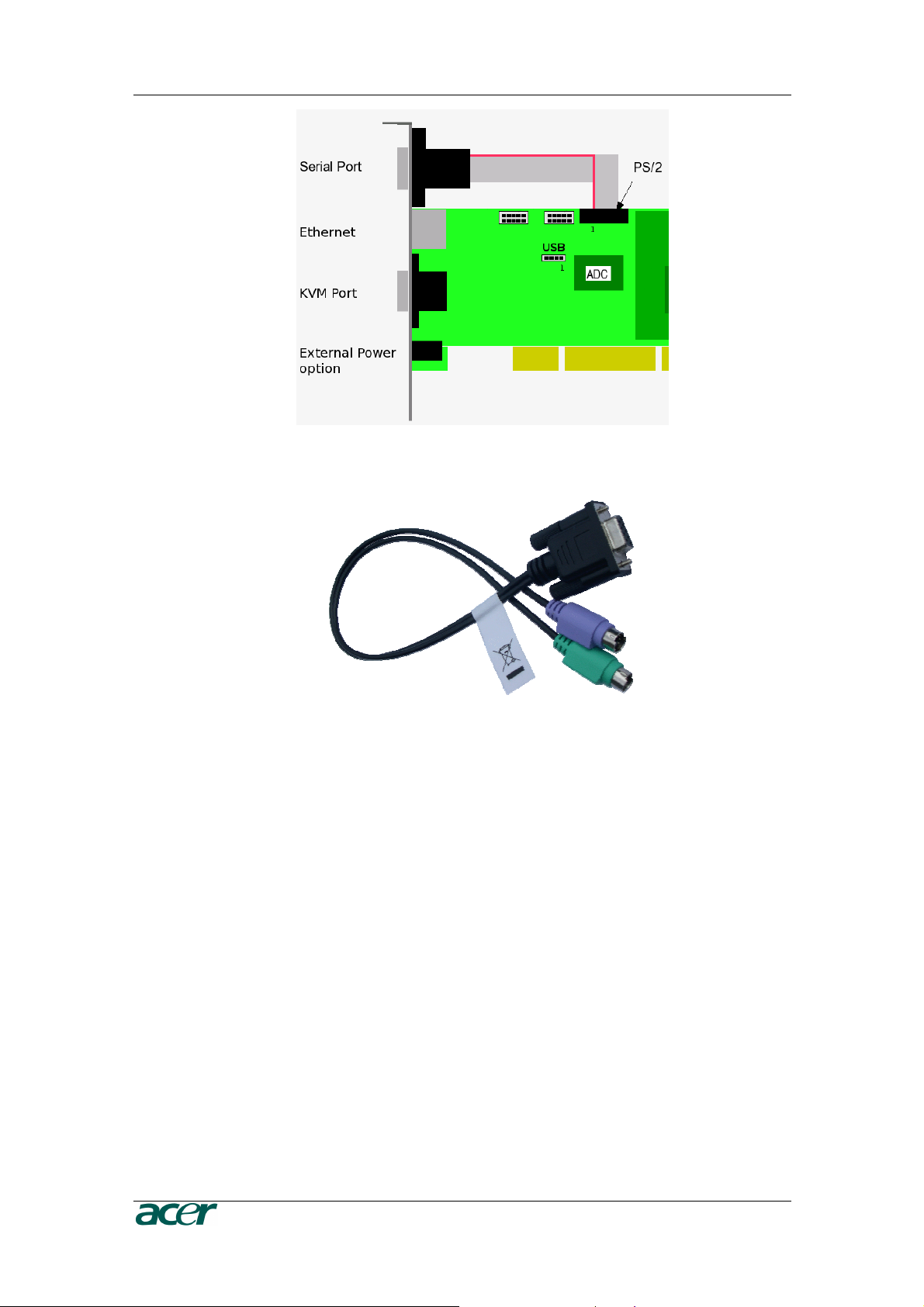
Figure 10 ARMC/3P with PS/2
Figure 11 PS/2 System Cable
There are only 9 PS/2 pins on the ARMC/3P. Therfore the PS/2 system cable
offers only the connection from ARMC/3P to the server. Connecting local PS/2
mouse and keyboard to the server is no longer possible!
There are the following function restrictions:
- If using the Low-Profile Bracket, then there is no serial or PS/2 connection
possible. Except for using additional brackets for offering the missing
connection.
- If using the High-Profile Bracket, then you have either the serial connector
or the PS/2 connector. Except for using an additional bracket to offer the
missing connection.
- If using PS/2 connection from ARMC/3P to server, then the local mouse
and keyboard have to be connected via USB.
C
HAPTER
2:
I
NSTALLATION
11
Placing the ARMC/3P into the Server
Open the Server
In order to install the ARMC/3P you need to open the host system. Detach the host
from its power cable and follow the instructions of your system documentation.
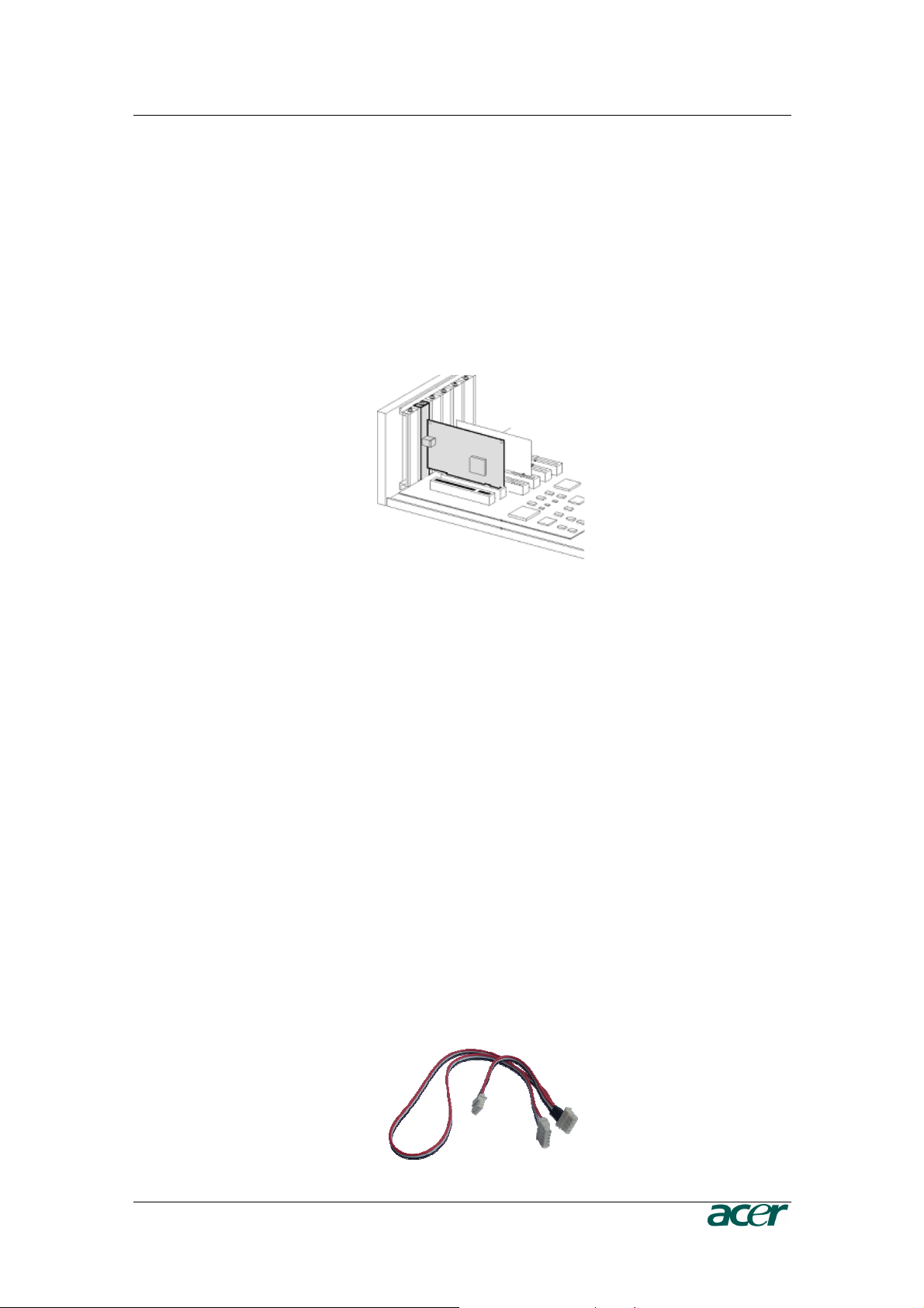
Plugging an ARMC/3P into a PCI Slot
ARMC/3P PCI
Place the ARMC/3P into a free PCI slot. You may use any PCI slot (33 or 66 MHz,
32 or 64 Bit, PCI-X).
Figure 12 Mounting the ARMC/3P into a PCI Slot
Connecting Power and Reset Cables
The ARMC/3P offers the possibility to remotely control both the power and the
reset functions of the host system. In order to support it, there is additional cabling
necessary. The preferred way for this cabling are the interfaces offered by IPMI.
However, if your host does not support IPMI you may use one of the other
possibilities.
Connecting over IPMB
This connection is used to power on or power off the system, or to perform a hard
reset. You must have a motherboard that supports IPMI 1.5 or higher and has a 3
or 4 pin IPMB connector as shown in Figure 14
o Connect the 5 pin connector of the IPMB cable with the 1x5 pin IPMB
connector on the ARMC/3P as shown in Figure 7.
o Connect the other ending of the cable with one of the IPMB connectors (3
or 4 pin connector) on the motherboard.
o Set the IPMI settings to IPMI over IPMB.
o Make sure that the IPMI function is enabled on the host system.
Figure 13 IPMB Cable
12 P
RODUCT
U
SER
G
UIDE
Figure 14 IPMB Connector
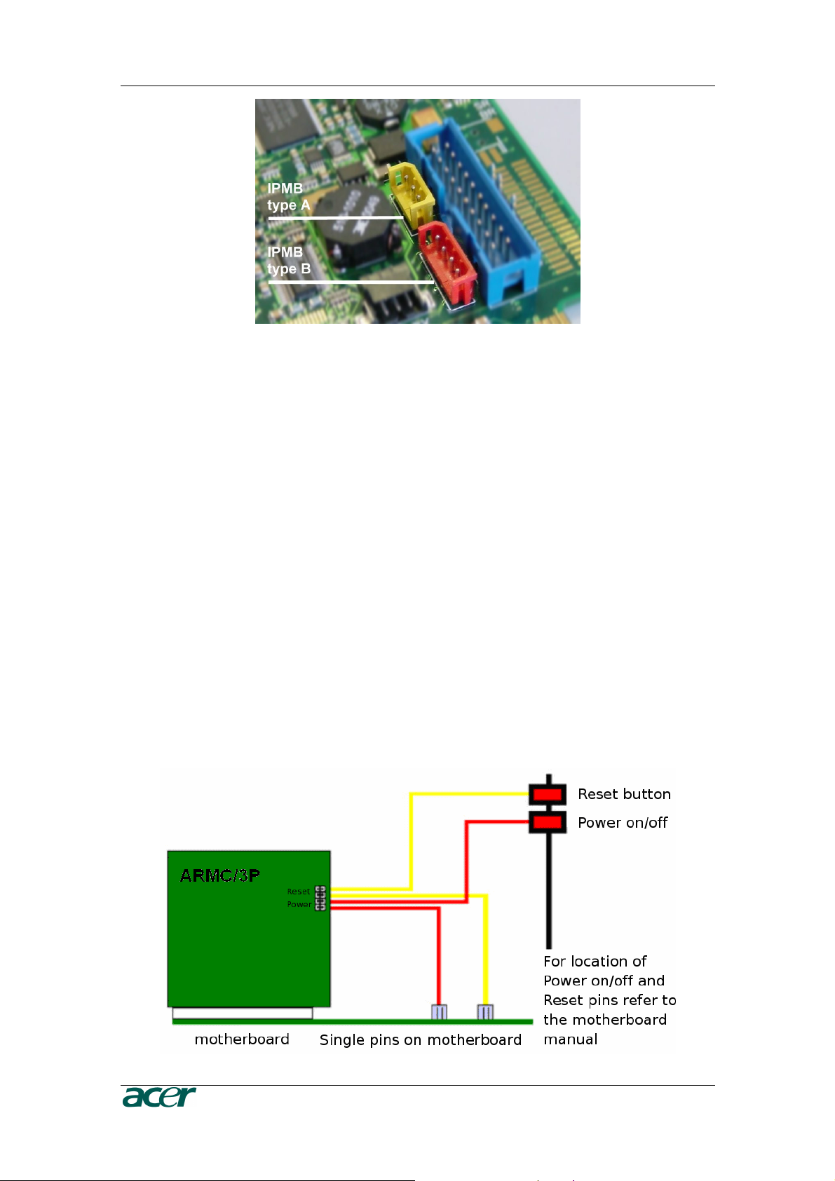
Connecting to ATX Control Signals
In case your system provides separated pins for reset and power on/off, perform
the following steps while referring to Figure 7 ARMC/3P Internal Connectors.
1. Find the cable connecting the front panel reset button and the motherboard.
2. Disconnect this cable from the motherboard and connect it to RST2 of the
ARMC/3P. Refer to Figure 9 for pin assignment.
3. Take the reset cable provided with the ARMC/3P and connect one end to the
motherboard’s reset connector (from where you just disconnected the cable to
the front panel), and the other end to RST1 of the RST/PWR connector of the
ARMC/3P.
4. Find the cable connecting the front panel power button and the motherboard.
5. Disconnect this cable from the motherboard and connect it to PWR2. For pin
assignment details, refer to Figure 9.
6. Take the power cable provided with the ARMC/3P and connect one end to the
motherboard’s power connector (from where you just discon- nected the cable
to the front panel), and the other end to PWR1 of the RST/PWR connector of
the ARMC/3P.
7. Check the cabling: there are four cables connected to the RST/PWR connector,
finally.
Figure 15 Power using Reset/Power Wires

C
HAPTER
2:
I
NSTALLATION
13
Connecting with Front Panel Connector
There are motherboards which do not have separated pins for power on/off and
reset. Both the reset and the power buttons are placed on the system’s front panel
and connected to the motherboard via a common front panel connector. To allow
the connection of the ARMC/3P’s remote reset and power on/off signals to those
motherboards a special front panel adapter has to be placed between the front
panel connector on the motherboard and the cable connector to the front panel.
Please ask your local service center for assistance.
Connecting Power Supply
The ARMC/3P offers the possibility to be powered internally by the host system
using the ATX Power Adaptor cable or powered externally using the external
Power adaptor. (see Package Contents).
Connecting Power using ATX Power Cable Adaptor
If the host system provides an ATX 20 or ATX 24 (EPS) connection from the power
supply to the motherboard, this cable can be extended with the delivered ATX
Power Cable Adaptor. In that case the ARMC/3P is powered internally using the
5V Standby Power of the host power supply. There is no other external power
supply necessary.
For connecting the ATX Power Cable Adaptor obey the following steps while
referring to Figure 7.
1. Power off the host and disconnect it from the power line.
2. Find the ATX cable connecting the host system power supply and the
motherboard and remove the cable.
3. Exchange the disconnected cable with the delivered 20-pole ATX Power Cable
Adaptor or the 24-pole ATX Power Cable Adaptor (EPS) cable. Then, connect
the male connector of the enclosed ATX Power Cable Adaptor to the power
supply of the host system and connect the female connector of the enclosed
ATX Power Cable Adaptor to the power connector of the motherboard.
4. Connect the ATX Power Cable Adaptor male connector on the ARMC/3P with
the 5 pin female connector of the ATX Power Cable Adaptor. Refer to Figure 16
ARMC/3P Host Power pins
5. Check the cabling, finally.
Note: Powering the ARMC/3P using ATX Power Cable Adaptor solution
requires Standard ATX Power Supply with 5V/2A Standby Power. Refer to
the host system and/or power supply manual if the host system and the host
power supply fully support the ATX standard.

14 P
RODUCT
U
SER
G
UIDE
Figure 16 Power using ATX Power Cable Adaptor
Connecting Optional External Power Supply
To allow the ARMC/3P to operate independently from the server system it is
possible to connect the card to an external power supply. From the technical point
of view any power supply can be used as long as the following specifications are
met:
Table 3 Voltage and Power Specification
Parameter Value
Voltage 5V
Current >= 1A
Pinning Plus on inner connector
Dimension 2.1 mm diameter
We recommend a 5V /1A power supply. Contact your local sales representative for
an Acer approved power supply.
Important: Any standard power supply compliant with the
requirements stated above may be used. Nevertheless, any
warranty from Acer voids if non-Acer power supplies are used in
conjunction with the ARMC/3P. Check for the Acer approval label
on the external power supply in order to preserve your
manufacturer’s warranty.
Connecting Keyboard and Mouse
Keyboard and mouse data are transmitted via USB into the server system.
Connect the USB plug into the appropriate socket on the server. Local USB
keyboard and mouse could be plugged into the host directly and parallel to the
ARMC/3P VGA-USB cable.

C
HAPTER
2:
I
NSTALLATION
15
Connecting Ethernet
The bracket of the ARMC/3P provides a RJ45 connector for Ethernet. The connec-
tor is used either for a 100 Mbps 100Base-TX connection or for a 10 Mbps
10BASE-T connection. The adapter can sense the connection speed and will
adjust to the appropriate operation mode automatically.
10 Mbps Connection
For 10BASE-T Ethernet networks the Fast Ethernet adapter uses category 3, 4, or
5 UTP cable. To establish a 10 Mbps connection, the cable has to be connected to
a 10BASE-T hub.
1. Make sure that the cable is wired appropriately for a standard 10BASE-T
adapter.
2. Align the RJ45 plug with the notch on the adapter ’s connector and insert it into
the adapter ’s connector.
100 Mbps Connection
For 100BASE-TX Ethernet networks the ARMC/3P supports category 5 UTP
cabling. To establish a 100 Mbps connection, the cable has to be connected to a
100BASE- TX hub.
1. Make sure that the cable is wired appropriately for a standard 100BASE-TX
adapter.
2. Align the RJ45 plug with the notch on the adapter ’s connector and insert it into
the adapter ’s connector.
Important: The UTP wire pairs and configuration for 100 BASE-TX
cable are identical to those for 10 BASE-T cable when used with
category 5 UTP cable.


C
HAPTER
3:
C
ONFIGURATION
17
Chapter 3: Configuration
Initial Configuration
The ARMC/3P’s communication interfaces are all based on TCP/IP. It comes
preconfigured with the IP configuration listed in Table 4 Initial Network Configuration.
Table 4 Initial Network Configuration
Parameter Value
IP auto configuration DHCP
IP address none
Netmask 255.255.255.0
Gateway none
IP access control none
Important: If the DHCP connection fails on boot up, the ARMC/3P
will not have an IP adresss.
If this initial configuration does not meet your requirements, the following describes the
initial IP configuration that is necessary to access the ARMC/3P for the first time.
ARMC/3P Psetup Tool
The psetup
tool
is
used
to
determine
the
IP
addr
ess
assigned
to
the
ARMC/3P
by
the
DHCP
server
or
to
change
the
device’s
initial
network
configuration.
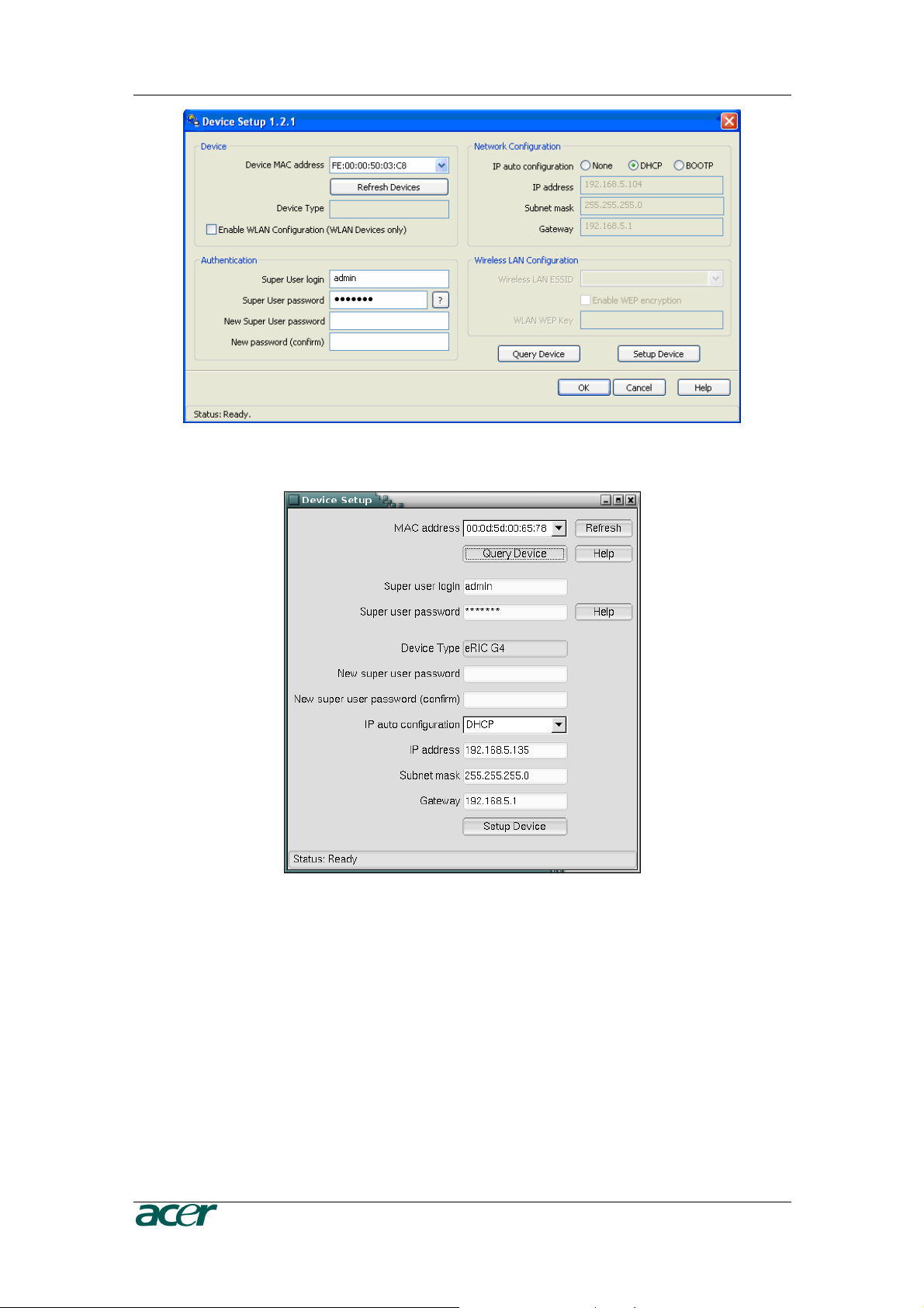
Using the Psetup Tool via Graphical User Interface
Connect the ARMC/3P to your computer via local network. Start the psetup tool,
which can be found on your ARMC/3P CD, on the computer in which the ARMC/3P
is installed or any other computer which is part of the same local network.
Note: If your network provides a properly configured DHCP server the
ARMC/3P should be automatically assigned an IP address. Please ask your
DHCP admin for the IP address the ARMC/3P got from the DHCP server.
A window opens as seen in Figure 17 (on a Windows OS) and Figure 18 ARMC/3P
Psetup Tool (Linux Version).
18 P
RODUCT
U
SER
G
UIDE
Figure 17 ARMC/3P Psetup Tool (Windows Version)
Figure 18 ARMC/3P Psetup Tool (Linux Version)
Running the Linux Psetup Tool via Command Line
The following list shows the command syntax and their usage:
--mac <MAC address of the device>
Shows the current network configuration.
--ip <neue IP address>
Set a new IP address.
 Loading...