


 Loading...
AR360 F1 Series
User Guide
Copyright © 2010. All Rights Reserved.
Acer AR360 F1 Series
User Guide
Acer AR360 F1
Model Number :
Serial Number:
Purchase Date:
Place of Purchase:
iii
Information for your safety and comfort
Safety instructions
Read these instructions carefully. Keep this document for future reference. Follow all warnings and instructions marked on the product.
Turning the product off before cleaning
Unplug this product from the wall outlet before cleaning. Do not use liquid cleaners or aerosol cleaners. Use a damp cloth for cleaning.
CAUTION for plug as disconnecting device
Observe the following guidelines when connecting and disconnecting power to the power supply unit:
•Install the power supply unit before connecting the power cord to the AC power outlet.
•Unplug the power cord before removing the power supply unit from the computer.
•If the system has multiple sources of power, disconnect power from the system by unplugging all power cords from the power supplies.
CAUTION for accessibility
Be sure that the power outlet you plug the power cord into is easily accessible and located as close to the equipment operator as possible. When you need to disconnect power to the equipment, be sure to unplug the power cord from the electrical outlet.
Warnings
•Do not use this product near water.
•Do not place this product on an unstable cart, stand or table. If the product falls, it could be seriously damaged.

iv
•Slots and openings are provided for ventilation to ensure reliable operation of the product and to protect it from overheating. These openings must not be blocked or covered. The openings should never be blocked by placing the product on a bed, sofa, rug or other similar surface. This product should never be placed near or over a radiator or heat register, or in a built-in installation unless proper ventilation is provided.
•Never push objects of any kind into this product through cabinet slots as they may touch dangerous voltage points or short-out parts that could result in a fire or electric shock. Never spill liquid of any kind onto or into the product.
•To avoid damage of internal components and to prevent battery leakage, do not place the product on a vibrating surface.
•Never use it under sporting, exercising, or any vibrating environment which will probably cause unexpected short current or damage rotor devices, HDD, Optical drive, and even exposure risk from lithium battery pack.
•This product is not suitable for use with visual display workplace devices according to B2 of the German Ordinance for Work with Visual Display Units.
Using electrical power
•This product should be operated from the type of power indicated on the marking label. If you are not sure of the type of power available, consult your dealer or local power company.
•Do not allow anything to rest on the power cord. Do not locate this product where people will walk on the cord.
•If an extension cord is used with this product, make sure that the total ampere rating of the equipment plugged into the extension cord does not exceed the extension cord ampere rating. Also, make sure that the total rating of all products plugged into the wall outlet does not exceed the fuse rating.
•Do not overload a power outlet, strip or receptacle by plugging in too many devices. The overall system load must not exceed 80% of the branch circuit rating. If power strips are used, the load should not exceed 80% of the power strip's input rating.
•This product's power supply is equipped with a three-wire grounded plug. The plug only fits in a grounded power outlet. Make sure the power outlet is properly grounded before inserting the power supply plug. Do not insert the plug into a non-grounded power outlet. Contact your electrician for details.
Warning! The grounding pin is a safety feature. Using a power outlet that is not properly grounded may result in electric shock and/or injury.

v
Note: The grounding pin also provides good protection from unexpected noise produced by other nearby electrical devices that may interfere with the performance of this product.
•Use the product only with the supplied power supply cord set. If you need to replace the power cord set, make sure that the new power cord meets the following requirements: detachable type, UL listed/CSA certified, VDE approved or its equivalent, 4.6 meters (15 feet) maximum length.
Product servicing
Do not attempt to service this product yourself, as opening or removing covers may expose you to dangerous voltage points or other risks. Refer all servicing to qualified service personnel.
Unplug this product from the wall outlet and refer servicing to qualified service personnel when:
•the power cord or plug is damaged, cut or frayed
•liquid was spilled into the product
•the product was exposed to rain or water
•the product has been dropped or the case has been damaged
•the product exhibits a distinct change in performance, indicating a need for service
•the product does not operate normally after following the operating instructions
Note: Adjust only those controls that are covered by the operating instructions, since improper adjustment of other controls may result in damage and will often require extensive work by a qualified technician to restore the product to normal condition.
This server must be placed in a restricted access location.
CAUTION: Danger of explosion if battery is incorrectly replaced. Replace only with the same or equivalent type recommended by the manufacturer. Dispose of used batteries according to the manufacturer’s instructions.

vi
Additional safety information
Your device and its enhancements may contain small parts. Keep them out of the reach of small children.
Disposal instructions
Do not throw this electronic device into the trash when discarding. To minimize pollution and ensure utmost protection of the global environment, please recycle. For more information on the Waste from Electrical and Electronics Equipment (WEEE) regulations, visit
http://www.acer-group.com/public/Sustainability/sustainability01.htm.
Mercury advisory
For projectors or electronic products containing an LCD/CRT monitor or display: Lamp(s) inside this product contain
mercury and must be recycled or disposed of according to local, state or federal laws. For more information, contact the Electronic Industries Alliance at www.eiae.org. For lamp-specific disposal information, check www.lamprecycle.org.
Tips and information for comfortable use
Computer users may complain of eyestrin and headaches after prolonged use. Users are also at risk of physical injury after long hours of working in front of a computer. Long work periods, bad posture, poor work habits, stress, inadequate working conditions, personal health and other factors greatly increase the risk of physical injury.
Incorrect computer usage may lead to carpal tunnel syndrome, tendonitis, tenosynovitis or other musculoskeletal disorders. The following symptoms may appear in the hands, wrists, arms, shoulders, neck or back:
•numbness, or a burning or tingling sensation
•aching, soreness or tenderness
•pain, swelling or throbbing
•stiffness or tightness
•coldness or weakness
vii
If you have these symptoms, or any other recurring or persistent discomfort and/or pain related to computer use, consult a physician immediately and inform your company's health and safety department.
The following section provides tips for more comfortable computer use.
Finding your comfort zone
Find your comfort zone by adjusting the viewing angle of the monitor, using a footrest, or raising your sitting height to achieve maximum comfort. Observe the following tips:
•refrain from staying too long in one fixed posture
•avoid slouching forward and/or leaning backward
•stand up and walk around regularly to remove the strain on your leg muscles
•take short rests to relax your neck and shoulders
•avoid tensing your muscles or shrugging your shoulders
•install the external display, keyboard and mouse properly and within comfortable reach
•if you view your monitor more than your documents, place the display at the center of your desk to minimize neck strain
Taking care of your vision
Long viewing hours, wearing incorrect glasses or contact lenses, glare, excessive room lighting, poorly focused screens, very small typefaces and low-contrast displays could stress your eyes. The following sections provide suggestions on how to reduce eyestrain.
Eyes
•Rest your eyes frequently.
•Give your eyes regular breaks by looking away from the monitor and focusing on a distant point.
•Blink frequently to keep your eyes from drying out.
Display
•Keep your display clean.

viii
•Keep your head at a higher level than the top edge of the display so your eyes point downward when looking at the middle of the display.
•Adjust the display brightness and/or contrast to a comfortable level for enhanced text readability and graphics clarity.
•Eliminate glare and reflections by:
•placing your display in such a way that the side faces the window or any light source
•minimizing room light by using drapes, shades or blinds
•using a task light
•changing the display's viewing angle
•using a glare-reduction filter
•using a display visor, such as a piece of cardboard extended from the display's top front edge
•Avoid adjusting your display to an awkward viewing angle.
•Avoid looking at bright light sources, such as open windows, for extended periods of time.
Developing good work habits
Develop the following work habits to make your computer use more relaxing and productive:
•Take short breaks regularly and often.
•Perform some stretching exercises.
•Breathe fresh air as often as possible.
•Exercise regularly and maintain a healthy body.
Warning! We do not recommend using the computer on a couch or bed. If this is unavoidable, work for only short periods, take breaks regularly, and do some stretching exercises.
ix
Regulations and safety notices
FCC notice
This device has been tested and found to comply with the limits for a Class A digital device pursuant to Part 15 of the FCC rules. These limits are designed to provide reasonable protection against harmful interference in a residential installation. This device generates, uses, and can radiate radio frequency energy and, if not installed and used in accordance with the instructions, may cause harmful interference to radio communications.
However, there is no guarantee that interference will not occur in a particular installation. If this device does cause harmful interference to radio or television reception, which can be determined by turning the device off and on, the user is encouraged to try to correct the interference by one or more of the following measures:
•Reorient or relocate the receiving antenna.
•Increase the separation between the device and receiver.
•Connect the device into an outlet on a circuit different from that to which the receiver is connected.
•Consult the dealer or an experienced radio/television technician for help.
Notice: Shielded cables
All connections to other computing devices must be made using shielded cables to maintain compliance with FCC regulations. In compliance with FCC regulations, use shielded cables to connect to other computing devices. A duallink cable is recommended for DVI output.
Notice: Peripheral devices
Only peripherals (input/output devices, terminals, printers, etc.) certified to comply with the Class A limits may be attached to this equipment. Operation with non-certified peripherals is likely to result in interference to radio and TV reception.
Caution
Changes or modifications not expressly approved by the manufacturer could void the user's authority, which is granted by the Federal Communications Commission, to operate this computer.

x
Operation conditions
This device complies with Part 15 of the FCC Rules. Operation is subject to the following two conditions: (1) this device may not cause harmful interference, and (2) this device must accept any interference received, including interference that may cause undesired operation.
Notice: Canadian users
This Class A digital apparatus complies with Canadian ICES-003.
Remarque à l'intention des utilisateurs canadiens
Cet appareil numérique de la classe B est conforme a la norme NMB-003 du Canada.
Compliant with Russian regulatory certification
Notice for Australia
For safety reasons, only connect headsets with a telecommunications compliance label. This includes customer equipment previously labelled permitted or certified.
Notice for New Zealand
1The grant of a Telepermit for any item of terminal equipment indicates only that Telecom has accepted that the item complies with minimum conditions for connection to its network. It indicates no endorsement of the product by Telecom, nor does it provide any sort of warranty. Above all, it provides no assurance that any item will work correctly in all respects with another item of Telepermitted equipment of a different make or model, nor does it imply that any product is compatible with all of Telecom's network services.
2This equipment is not capable, under all operating conditions, of correct operation at the higher speeds for which it is designed. Telecom will accept no responsibility should difficulties arise in such circumstances.
3Some parameters required for compliance with Telecom's Telepermit requirements are dependent on the equipment (PC) associated with this device. The associated equipment shall be set to operate within the following limits for compliance with Telecom's Specifications:
xi
aThere shall be no more than 10 call attempts to the same number within any 30 minute period for any single manual call initiation, and
bThe equipment shall go on-hook for a period of not less than 30 seconds between the end of one attempt and the beginning of the next call attempt.
4Some parameters required for compliance with Telecom's Telepermit requirements are dependent on the equipment (PC) associated with this device. In order to operate within the limits for compliance with Telecom's specifications, the associated equipment shall be set to ensure that automatic calls to different numbers are spaced such that there is not less than 5 seconds between the end of one call attempt and the beginning of another.
5This equipment shall not be set up to make automatic calls to Telecom's 111 Emergency Service.
6This device is equipped with pulse dialing while the Telecom standard is DTMF tone dialing. There is no guarantee that Telecom lines will always continue to support pulse dialing.
7Use of pulse dialing, when this equipment is connected to the same line as other equipment, may give rise to bell tinkle or noise and may also cause a false answer condition. Should such problems occur, the user should NOT contact the telecom Fault Service.
8This equipment may not provide for the effective hand-over of a call to another device connected to the same line.
9Under power failure conditions this appliance may not operate. Please ensure that a separate telephone, not dependent on local power, is available for emergency use.
Notice: BSMI
Power Supply Unit (PSU) statement
Power supply unit (PSU) redundancy claim ensures that the system may continue to run normally in the event one power supply unit becomes
xii
inoperable. Under normal operation, both power supplies share the system loading.
Laser compliance statement
The CD or DVD drive used with this computer is a laser product.
The CD or DVD drive's classification label (shown below) is located on the drive.
CLASS 1 LASER PRODUCT
CAUTION: INVISIBLE LASER RADIATION WHEN OPEN. AVOID EXPOSURE TO BEAM.
Appareil à laser de classe 1
Attention : Radiation laser visible et invisible en cas d’ouverture. Éviter toute exposition aux rayons.
Laserprodukt der Klasse 1
Achtung: Beim Öffnen werden unsichtbare Laserstrahlen freigelegt. Setzen Sie sich diesen Strahlen nicht aus.
Prodotto laser di classe 1
Attenzione: Radiazioni laser invisibili in caso d’apertura. Evitare l’esposizione ai raggi.
Producto láser de Clase 1
Precaución: Cuando está abierta, hay radiación láser. Evite una exposición al haz de luz.
Produto Laser de Classe 1
Precauçăo: Radiaçăo laser invisível quando aberto. Evite exposiçăo ao feixe.
Laserproduct klasse 1
Voorzichtig: Onzichtbare laserstraling indien geopend. Voorkom blootstelling aan straal.
Declaration of Conformity for EU countries
Hereby, Acer, declares that this system is in compliance with the essential requirements and other relevant provisions of Directive 1999/5/EC.
List of applicable countries
This device must be used in strict accordance with the regulations and constraints in the country of use. For further information, please contact local office in the country of use. Please see http://ec.europa.eu/enterprise/rtte/ implem.htm for the latest country list.
1 System tour
Overview
External and internal structure Front panel
Rear panel
Internal components Mainboard
2 System setup
Setting up the system Pre-installation requirements
Connecting peripherals Turning on the system
To power on the system: Power-on problems
Configuring the system OS Turning off the system
3 System upgrades
Installation precautions ESD precautions
Pre-installation instructions Post-installation instructions Removal and replacement procedures
Extend the server from the rack Power down the server
Remove the server from the rack Opening the server
Configuring the storage devices Accessing the drive bays
Hard disk drive configuration guidelines Determining drive status
Removing and installing a 2.5” hard disk drive Removing and installing an optical drive
Installing and removing the power supply Power supply failure
Replacing the power supply Replacing a system fan
Replacing the processor and heatsink Removing the heatsink Installing a heatsink
Upgrading the processor
1 |
Contents |
|
2
3
3
6
8
9
17
18
18
19
20
20
20
22
23
25
27
27
27
28
29
29
30
31
32
34
34
34
35
36
37
41
42
42
43
45
45
46
48
xiv |
|
Upgrading the system memory |
51 |
Installing a memory module: |
58 |
Removing a memory module: |
60 |
Installing an expansion card |
61 |
Installing a SAS card |
61 |
Installing the right riser card |
63 |
Rack installation information |
66 |
System rack installation |
67 |
Vertical mounting hole pattern |
69 |
Installing the system into the rack |
70 |
4 System BIOS |
77 |
Introduction |
78 |
The BIOS setup utility |
78 |
Changing configuration data |
78 |
Main setup |
80 |
Advanced Settings |
82 |
Boot Features |
82 |
Processor & Clock Options |
84 |
Advanced Chipset Control |
87 |
IDE/SATA configuration |
91 |
PCI/PnP configuration |
94 |
Super IO Configuration |
95 |
Hardware Health Configuration |
96 |
ACPI configuration |
99 |
Security Settings |
101 |
System Management Settings |
104 |
Product Information |
104 |
Remote Access Configuration |
106 |
DMI Event Logging |
107 |
Boot Settings |
109 |
Boot Device Priority |
109 |
Hard Disk Drives |
110 |
CD/DVD Drive |
110 |
Exit |
111 |
5 System troubleshooting |
115 |
Resetting the system |
116 |
Initial system startup problems |
116 |
BIOS error beep codes |
117 |
Initial troubleshooting checklist |
118 |
Hardware diagnostic testing |
119 |
Checking the boot-up status |
119 |
xv
Verifying the condition of the storage devices |
120 |
Confirming loading of the operating system |
120 |
Specific problems and corrective actions |
121 |
Appendix A: Server management tools |
125 |
Server management overview |
126 |
RAID configuration utilities |
127 |
Intel onboard SATA RAID Creation |
127 |
Adaptec onboard SATA RAID Creation |
128 |
Appendix B: Rack mount configuration |
131 |
Rack installation information |
132 |
System rack installation |
134 |
Vertical mounting hole pattern |
135 |
Installing the system into the rack |
136 |
Appendix C: Acer Smart Console |
141 |
Using Acer Smart Console |
142 |
Software requirements |
142 |
Accessing Acer Smart Console |
143 |
Acer Smart Console user interface |
144 |
System Information |
144 |
Server Health |
145 |
Configuration |
147 |
Remote Control |
157 |
Launch SOL |
159 |
Virtual Media |
160 |
Maintenance |
162 |
KVM function description |
163 |
Exit |
169 |
Index |
171 |
xvi
1 System tour
2 |
1 System tour |
Overview
The AR360 F1 is a high-performance 1U rack-mount dual-socket server that supports up to two new generations of Intel architecture processors (Intel® Xeon 5500 series and Intel® Xeon 5600 series processors), DDR3 memory technology, PCI Express Gen2 (5.0Gb/s) quad onboard gigabit Ethernet controllers with Intel® I/O Acceleration Technology I/OAT, VT-d and iSCSI boot and integrated BMC management feature.
The AR360 F1 targets medium businesses that require server solution combined with performance, reliability and expandability to support applications such as FTP server, file/printer server, data center, data center and Internet/Intranet server. The AR360 F1 is a flexible and highly reliable rack-mount server that satisfy growing businesses and customers’ needs.
System features and support
•Eight 2.5-inch SAS/SATA hard disk drives.
•Hot-plug redundant system fans
•Dual Intel® Xeon 5500 / 5600 processors
•Eighteen DIMM slots that support a maximum of 192 GB (registered) or 48 GB (unbuffered) memory
3
External and internal structure
Front panel
The illustration below shows the system front panel.
With 2.5-inch HDD bays
|
|
|
|
|
|
|
|
|
|
|
|
|
|
|
|
|
|
|
|
|
|
|
|
|
|
|
|
|
|
|
|
|
|
|
|
|
|
|
|
|
|
|
|
|
|
|
|
|
|
|
|
|
|
|
|
|
|
|
|
|
|
|
|
|
|
|
|
|
|
|
|
|
|
|
|
|
|
|
|
|
|
|
|
|
|
|
|
|
|
|
|
|
|
|
|
|
|
|
|
|
|
|
|
|
|
|
|
|
|
|
|
|
|
|
|
|
|
|
|
|
|
|
|
|
|
|
|
|
|
|
|
|
|
|
|
|
|
|
|
|
|
|
|
|
|
|
|
|
|
|
|
|
|
|
|
|
|
|
|
|
|
|
|
|
|
|
|
|
|
|
|
|
|
|
|
|
|
|
|
|
|
|
|
|
|
|
|
|
|
|
|
|
|
|
|
|
|
|
|
|
|
|
|
|
|
|
|
|
|
|
|
|
|
|
|
|
|
|
|
|
|
|
|
|
|
|
|
|
|
|
|
|
|
|
|
|
|
|
|
|
|
|
|
|
|
|
|
|
|
|
|
|
|
|
|
|
|
|
|
|
|
|
|
|
|
|
|
|
|
|
|
|
|
|
|
|
|
|
|
|
|
|
|
|
|
|
|
|
|
|
|
|
|
|
|
|
|
|
|
|
|
|
|
|
|
|
|
|
|
|
|
|
|
|
|
|
|
|
|
|
|
|
|
|
|
|
|
|
|
|
|
|
|
|
|
|
|
|
|
|
|
|
|
|
|
|
|
|
|
|
|
|
|
|
|
|
|
|
|
|
|
|
|
|
|
|
|
|
|
|
|
|
|
|
|
|
|
|
|
|
|
|
|
|
|
|
|
|
|
|
|
|
|
|
|
|
|
|
|
|
|
|
|
|
|
|
|
|
|
|
|
|
|
|
|
|
|
|
|
|
|
|
|
|
|
|
|
|
|
|
|
|
|
|
|
|
|
|
|
|
|
|
|
|
|
|
|
|
|
|
|
No. |
|
Icon |
Component |
||||||||||||||||||||||||||||||||||||
|
|
|
|
|
|
|
|
|
|
|
|
|
|
|
|
|
|
|
|
|
|
|
|
|
|
|
|
|
|
|
|
|
|
|
|
|
|
|
|
|
1 |
|
|
|
|
|
|
|
|
Optical drive |
|||||||||||||||||||||||||||||||
|
|
|
|
|
|
|
|
|
|
|
|
|
|
|
|
|
|
|
|
|
|
|
|
|
|
|
|
|
|
|
|
|
|
|
|
|
|
|
|
|
2 |
|
|
|
|
|
|
|
|
System ID / status / fault indicator |
|||||||||||||||||||||||||||||||
|
|
|
|
|
|
|
|
|
|
|
|
|
|
|
|
|
|
|
|
|
|
|
|
|
|
|
|
|
|
|
|
|
|
|
|
|
|
|
|
|
3 |
|
|
|
|
|
|
|
|
System ID button |
|||||||||||||||||||||||||||||||
|
|
|
|
|
|
|
|
|
|
|
|
|
|
|
|
|
|
|
|
|
|
|
|
|
|
|
|
|
|
|
|
|
|
|
|
|
|
|
|
|
4 |
|
|
|
|
|
|
|
|
LAN2 activity indicator |
|||||||||||||||||||||||||||||||
|
|
|
|
|
|
|
|
|
|
|
|
|
|
|
|
|
|
|
|
|
|
|
|
|
|
|
|
|
|
|
|
|
|
|
|
|
|
|
|
|
5 |
|
|
|
|
|
|
|
|
LAN1 activity indicator |
|||||||||||||||||||||||||||||||
6 |
Power button |
|
|
4 |
|
1 System tour |
|
|
|
|
|
No. |
Icon |
Component |
|
|
|
|
|
7 |
|
HDD activity indicator |
|
|
|
|
|
8 |
|
Power indicator |
|
|
|
|
|
9 |
|
Hot-plug HDD activity indicator |
|
|
|
|
|
10 |
|
Hot-plug HDD status indicator |
|
11Rack handles
122.5-inch hard disk drive (HDD) bays
Front panel LED indicator status
LED indicator |
LED color |
LED state |
Status |
|
|
|
|
|
|
Power |
Green |
On |
S0: Power ON |
|
indicator |
|
|
|
|
Green |
Blinking (1 Hz at |
S1: Sleep |
||
|
||||
|
|
50% duty cycle) |
|
|
|
|
|
|
|
|
N/A |
Off |
S4 |
|
|
|
|
|
|
|
N/A |
Off |
S5 |
|
|
|
|
|
|
HDD activity |
Amber |
Blinking |
HDD access |
|
indicator |
|
|
|
|
N/A |
Off |
No access |
||
|
||||
|
|
|
|
5
LED indicator |
LED color |
LED state |
Status |
|
|
|
|
|
|
System ID / |
Blue |
On |
System ID button |
|
status / fault |
|
|
pressed |
|
indicator |
|
|
|
|
Blue |
Blinking |
IPMI-activated system |
||
|
||||
|
|
|
ID |
|
|
|
|
|
|
|
Red |
On |
CPU overheat |
|
|
|
|
|
|
|
Red |
Fast Blink (1x/sec) |
Fan failure |
|
|
|
|
|
|
|
Red |
Slow Blink (1x/4sec) |
Power failure |
|
|
|
|
|
|
LAN activity |
Green |
On |
LAN Link / No Access |
|
indicators |
|
|
|
|
Green |
Blinking |
LAN Access |
||
(LAN1, |
||||
|
|
|
|
|
LAN2) |
N/A |
Off |
Disconnect / Idle |
|
|
|
|
|
6 |
1 System tour |
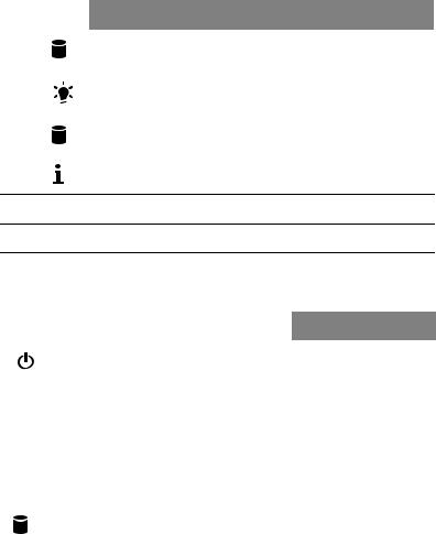
Rear panel
No. Component
1Power supply modules
2PS/2 mouse port
3Server management port (RJ-45) (10/100 Mbps)
4Low-profile PCI Express 2.0 x8 (x8 link) expansion slot
5Full-height PCI Express 2.0 x16 (x16 link) expansion slot
6Flex I/O expansion slot
7System ID indicator
8Gigabit LAN1 - 4 ports (10/100/1000 Mbps)
9Monitor port
10COM port
11USB 2.0 ports
12PS/2 keyboard port
7
Rear panel LED indicator status
LED indicator |
LED color |
LED state |
Status |
|
|
|
|
System ID LED |
N/A |
Off |
Normal |
|
|
|
|
|
Blue |
On |
System ID button pressed |
|
|
|
|
|
Blue |
Blinking |
IPMI-activated system ID |
|
|
|
|
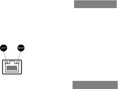
LAN port LED indicators
LED indicator |
LED color |
LED state |
Status |
|
|
|
|
RJ45 LED (Left) |
N/A |
Off |
No connection or 10 Mbps |
|
|
|
|
|
Green |
On |
100 Mbps |
|
|
|
|
|
Amber |
On |
1000 Mbps |
|
|
|
|
RJ45 LED (Right) |
Green |
On |
Active connection |
|
|
|
|
|
Green |
Blinking |
Transmit/Receive activity |
|
|
|
|
8 |
1 System tour |
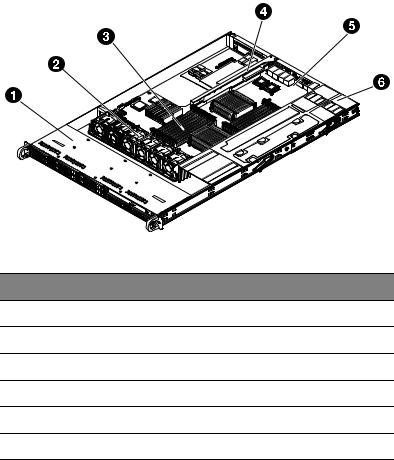
Internal components
No. Component
1Hard disk drive bay
2System fan modules
3Memory modules
4PCI riser board bracket assembly
5Mainboard
6Power supply module

9
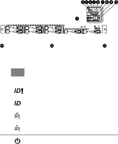
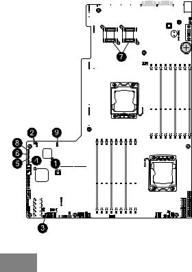
Mainboard
The mainboard becomes accessible once you open the system. It should look like the figure shown below.
3 |
2 |
10 |
1 System tour |
No. |
Connector |
Description |
|
|
|
1 |
P1-DIMM3A |
DDR3 sockets for processor 1 |
|
P1-DIMM3B |
|
|
P1-DIMM3C |
|
|
P1-DIMM2A |
|
|
P1-DIMM2B |
|
|
P1-DIMM2C |
|
|
P1-DIMM1A |
|
|
P1-DIMM1B |
|
|
P1-DIMM1C |
|
|
|
|
2 |
CPU2 |
Processor 2 socket |
|
|
|
3 |
JPW1 |
ATX 24-pin power connector |
|
|
|
4 |
JPW2/JPW3 |
12V 8-pin power connectors |
|
|
|
5 |
FAN1 |
Chassis fan 1 |
|
|
|
6 |
JPI2C |
Power supply SMB bus I2C header |
|
|
|
7 |
JPK1 |
NIC3/NIC4 LED headers |
|
|
|
8 |
FAN 7 |
CPU2 FAN (Reserved) |
|
|
|
9 |
FAN2 |
Chassis fan 2 |
|
|
|
10 |
FAN3 |
Chassis fan 3 |
|
|
|
11 |
IPMB1/ |
4-pin/3-pin external BMC I2C header |
|
JIPMB2 |
|
|
|
|
12 |
FAN 4 |
Chassis fan 4 |
|
|
|
13 |
FAN 5 |
Chassis fan 5 |
|
|
|
14 |
JF1 |
Front panel control header |
|
|
|
15 |
FAN 6 |
Chassis fan 6 |
|
|
|
16 |
T-SGPIO2 |
Serial General Purpose Input/Output header 2 |
|
|
|
11
No. |
Connector |
Description |
|
|
|
17 |
T-SGPIO1 |
Serial General Purpose Input/Output header 1 |
|
|
|
18 |
I-SATA0~5 |
SATA ports |
|
|
Note: I-SATA5 is reserved for an installed optical drive. |
|
|
|
19 |
USB 4/5 |
Front panel accessible USB headers (USB4/5) |
|
|
|
20 |
JL1 |
Chassis intrusion |
|
|
|
21 |
USB 6 |
Front panel accessible type A USB connector USB6 |
|
|
|
22 |
JTPM |
Trusted platform module header (JP8) |
|
|
|
23 |
COM2 |
Serial port 2 connection |
|
|
|
24 |
SXB3 |
Left side riser card slot |
|
|
|
25 |
SXB1 |
Left side riser card slot |
|
|
|
26 |
SXB2 |
Right side riser card slot |
|
|
|
27 |
UIOP |
Left side riser card slot |
|
|
|
28 |
ID |
System ID LED |
|
|
|
29 |
LAN3/LAN4 |
G-bit ethernet ports 3/4 |
|
|
|
30 |
LAN1/LAN2 |
G-bit ethernet ports 1/2 |
|
|
|
31 |
COM1 |
COM1 serial connection |
|
|
|
32 |
IPMI LAN |
IPMI dedicated LAN |
|
|
|
33 |
USB 0/1 |
Back panel USB 0/1 |
|
|
|
34 |
KB/MS |
PS2 keyboard/mouse |
|
|
|
35 |
USB 2/3 |
Internal 2-port USB header (USB 2/3) for tape drive |
|
|
|
36 |
COM1 |
COM1 serial connection |
|
|
|
37 |
JBT1 |
Onboard battery |
|
|
|
38 |
SP1 |
Onboard buzzer |
|
|
|
12 |
|
1 System tour |
|
|
|
|
|
No. |
Connector |
Description |
|
|
|
|
|
39 |
FAN8 |
CPU1 FAN (Reserved) |
|
|
|
|
|
40 |
CPU1 |
Processor 1 socket |
|
|
|
|
|
41 |
P2-DIMM1C |
DDR3 sockets for processor 2 |
|
|
P2-DIMM1B |
|
|
|
P2-DIMM1A |
|
|
|
P2-DIMM2C |
|
|
|
P2-DIMM2B |
|
|
|
P2-DIMM2A |
|
|
|
P2-DIMM3C |
|
|
|
P2-DIMM3B |
|
|
|
P2-DIMM3A |
|
|
|
|
|
|
42 |
USB7 |
Front panel accessible USB headers (USB7) |
|
|
|
|
|
13
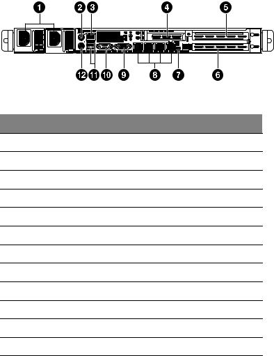
Mainboard jumper settings
|
|
|
|
|
|
|
|
|
|
|
|
|
|
|
|
|
|
|
|
|
|
|
|
|
|
|
|
|
|
|
|
|
|
|
|
|
|
|
|
|
|
|
|
|
|
|
|
|
|
|
|
|
|
|
|
|
|
|
|
|
|
|
|
|
|
|
|
|
|
|
|
|
|
|
|
|
|
|
|
|
|
|
|
|
|
|
|
|
|
|
|
|
|
|
|
|
|
|
|
|
|
|
|
|
|
|
|
|
|
|
|
|
|
|
|
|
|
|
|
|
|
|
|
|
|
|
|
|
|
|
|
|
|
|
|
|
|
|
|
|
|
|
|
|
|
|
|
|
|
|
|
|
|
|
|
|
|
|
|
|
|
|
|
|
|
|
|
|
|
|
|
|
|
|
|
|
|
|
|
|
|
|
|
|
|
|
|
|
|
|
|
|
|
|
|
|
|
|
|
|
|
|
|
|
|
|
|
|
|
|
|
|
|
|
|
|
|
|
|
|
|
|
|
|
|
|
|
|
|
|
|
|
|
|
|
|
|
|
|
|
|
|
|
|
|
|
|
|
|
|
|
|
|
|
|
|
|
|
|
|
|
|
|
|
|
|
|
|
|
|
|
|
|
|
|
|
|
|
|
|
|
|
|
|
|
|
|
|
|
|
|
|
|
|
|
|
|
|
|
|
|
|
|
|
|
|
|
|
|
|
|
|
|
|
|
|
|
|
|
|
|
|
|
|
|
|
|
|
|
|
|
|
|
|
|
|
|
|
|
|
|
|
|
|
|
|
|
|
|
|
|
|
|
|
|
|
|
|
|
|
|
|
|
|
|
|
|
|
|
|
|
|
|
|
|
|
|
|
|
|
|
|
|
|
|
|
|
|
|
|
|
|
|
|
|
|
|
|
|
|
|
|
|
|
|
|
|
|
|
|
|
|
|
|
|
|
|
|
|
|
|
|
|
|
|
|
|
|
|
|
|
|
|
|
|
|
|
|
|
|
|
|
|
|
|
|
|
|
|
|
|
|
|
|
|
|
|
|
|
|
|
|
|
|
|
|
|
|
|
|
|
|
|
|
|
|
|
|
|
|
|
|
|
|
|
|
|
|
|
|
|
|
|
|
|
|
|
|
|
|
|
|
|
|
|
|
|
|
|
|
|
|
|
|
|
|
|
|
|
|
|
|
|
|
|
|
|
|
|
|
|
|
|
|
|
|
|
|
|
|
|
|
|
|
|
|
|
|
|
|
|
|
|
|
|
|
|
|
|
|
|
|
|
|
|
|
|
|
|
|
|
|
|
|
|
|
|
|
|
|
|
|
|
|
|
|
|
|
|
|
|
|
|
|
|
|
|
|
|
|
|
|
|
|
|
|
|
|
|
|
|
|
|
|
|
|
|
|
|
|
|
|
|
|
|
|
|
|
|
|
|
|
|
|
|
|
|
|
|
|
|
|
|
|
|
|
|
|
|
|
|
|
|
|
|
|
|
|
|
|
|
|
|
|
|
|
|
|
|
|
|
|
|
|
|
|
|
|
|
|
|
|
|
|
|
|
|
|
|
|
|
|
|
|
|
|
|
|
|
|
|
|
|
|
|
|
|
|
|
|
|
|
|
|
|
|
|
|
|
|
|
|
|
|
|
|
|
|
|
|
|
|
|
|
|
|
|
|
|
|
|
|
|
|
|
|
|
|
|
|
|
|
|
|
|
|
|
|
|
|
|
|
|
|
|
|
|
|
|
|
|
|
|
|
|
|
|
|
|
|
|
|
|
|
|
|
|
|
|
|
|
|
|
|
|
|
|
|
|
|
|
|
|
|
|
|
|
|
|
|
|
|
|
|
|
|
|
|
|
|
|
|
|
|
|
|
|
|
|
|
|
|
|
|
|
|
|
|
|
|
|
|
|
|
|
|
|
|
|
|
|
|
|
|
|
|
|
|
|
|
|
|
|
No. |
Jumper |
Description |
|
|
Default Setting |
||||||||||||||||||||||||||
|
|
|
|
|
|
|
|
|
|
|
|
|
|
|
|
|
|
|
|
|
|
|
|
|
|
|
|
|
|
|
|
1 |
JBT1 |
Clear CMOS |
|
|
Instead of pins, this jumper consists |
||||||||||||||||||||||||||
|
|
|
|
|
|
|
|
|
|
|
|
|
|
|
|
|
|
|
|
|
|
|
of contact pads to prevent accidental |
||||||||
|
|
|
|
|
|
|
|
|
|
|
|
|
|
|
|
|
|
|
|
|
|
|
clearing of the CMOS contents. To |
||||||||
|
|
|
|
|
|
|
|
|
|
|
|
|
|
|
|
|
|
|
|
|
|
|
clear CMOS, disconnect the power |
||||||||
|
|
|
|
|
|
|
|
|
|
|
|
|
|
|
|
|
|
|
|
|
|
|
and short the CMOS pads with a |
||||||||
|
|
|
|
|
|
|
|
|
|
|
|
|
|
|
|
|
|
|
|
|
|
|
metal object such as a small |
||||||||
|
|
|
|
|
|
|
|
|
|
|
|
|
|
|
|
|
|
|
|
|
|
|
screwdriver. |
||||||||
|
|
|
|
|
|
|
|
|
|
|
|
|
|
|
|
|
|
|
|
|
|
|
|
|
|
|
|
|
|
|
|
2 |
JI2C1/ |
SMB to PCI-E slots |
|
|
Off (disable) |
||||||||||||||||||||||||||
|
JI2C2 |
|
|
|
|
|
|
|
|
|
|
|
|
|
|
|
|
|
|
|
|
|
|
|
|
|
|
|
|
|
|
|
|
|
|
|
|
|
|
|
|
|
|
|
|
|
|
|
|
|
|
|
|
|
|
|
|
|
|
|
|
|
|
3 |
JP3 |
ME Mode Select |
|
|
Pins 2~3 (disable) |
||||||||||||||||||||||||||
|
|
|
|
|
|
|
|
|
|
|
|
|
|
|
|
|
|
|
|
|
|
|
|
|
|
|
|
|
|
|
|
4 |
JP5 |
ME Recovery |
|
|
Open (normal) |
||||||||||||||||||||||||||
|
|
|
|
|
|
|
|
|
|
|
|
|
|
|
|
|
|
|
|
|
|
|
|
|
|
|
|
|
|
|
|

14 |
|
|
1 System tour |
|
|
|
|
|
|
No. |
Jumper |
Description |
Default Setting |
|
|
|
|
|
|
5 |
JPB |
BMC Enabled |
Pins 1~2 (enable) |
|
|
|
|
|
|
6 |
JPG1 |
VGA Enable |
Pins 1~2 (enable) |
|
|
|
|
|
|
7 |
JPL1/ |
GLAN1/GLAN2 |
Pins 1~2 (enable) |
|
|
JPL2 |
Enable |
|
|
|
|
|
|
|
8 |
JPRST1 |
BMC/PHY Enable |
Pins 1~2 (enable) |
|
|
|
|
|
|
9 |
JWD |
Watch Dog |
Pins 1~2 (reset) |
|
|
|
|
|
|
Note: Jumpers not indicated are for test purposes only.
Loading...