


 Loading...
IP-95
Motherboard
Socket 775
Intel Core 2 Duo
Intel Pentium D
Intel Pentium 4
Intel Celeron D
Intel Celeron
VIA P4M890 / VT8237R Plus
FSB1066
DDR2 533 or DDR 400
PCI Express
2x SATA 1.5Gb/s
5.1 Channel AC97 Audio
Appendix QIG Multilingual Utility & Driver Setup BIOS Setup Hardware

IP-95
User’s Manual
English + Multilingual QIG
1st Edition, October 2006
Copyright and Warranty Notice
The information in this document is subject to change without notice and does not represent a commitment on part of the vendor, who assumes no liability or responsibility for any errors that may appear in this manual.
No warranty or representation, either expressed or implied, is made with respect to the quality, accuracy or fitness for any particular part of this document. In no event shall the manufacturer be liable for direct, indirect, special, incidental or consequential damages arising from any defect or error in this manual or product.
Product names appearing in this manual are for identification purpose only and trademarks and product names or brand names appearing in this document are the property of their respective owners.
This document contains materials protected under International Copyright Laws. All rights reserved. No part of this manual may be reproduced, transmitted or transcribed without the expressed written permission of the manufacturer and authors of this manual.
If you do not properly set the motherboard settings, causing the motherboard to malfunction or fail, we cannot guarantee any responsibility.
ii |
IP-95 |

Contents
1. Hardware Setup ............................................................... |
1-1 |
|
1.1 |
Specifications .............................................................................. |
1-1 |
1.2 |
Motherboard Layout..................................................................... |
1-2 |
1.3 |
Choosing a Computer Chassis ....................................................... |
1-3 |
1.4 Installing Motherboard ................................................................. |
1-3 |
|
1.5 |
Checking Jumper Settings ............................................................ |
1-4 |
|
1.5.1 CMOS Memory Clearing Header and Backup Battery .............. |
1-4 |
1.6 |
Connecting Chassis Components................................................... |
1-6 |
|
1.6.1 ATX Power Connectors ........................................................ |
1-6 |
|
1.6.2 Front Panel Switches & Indicators Headers............................ |
1-7 |
|
1.6.3 FAN Power Connectors ........................................................ |
1-8 |
|
1.6.4 Chassis Speaker Connector .................................................. |
1-9 |
1.7 |
Installing Hardware.................................................................... |
1-10 |
|
1.7.1 CPU Socket 775 ................................................................ |
1-10 |
|
1.7.2 DDR2/DDR Memory Slots................................................... |
1-12 |
1.8 |
Connecting Peripheral Devices .................................................... |
1-13 |
|
1.8.1 Floppy and IDE Disk Drive Connectors ................................ |
1-13 |
|
1.8.2 Serial ATA Connectors ....................................................... |
1-14 |
|
1.8.3 Additional USB 2.0 Port Headers......................................... |
1-15 |
|
1.8.4 Internal Audio Connectors.................................................. |
1-15 |
|
1.8.5 Front Panel Audio Connection Header ................................. |
1-16 |
|
1.8.6 PCI and PCI Express X16, X1 Slots ..................................... |
1-17 |
1.9 |
Connecting Rear Panel I/O Devices ............................................. |
1-18 |
2. BIOS Setup....................................................................... |
2-1 |
|
3. Driver & Utility ................................................................. |
3-1 |
|
4. Multilingual Quick Installation Guide .............................. |
4-3 |
|
4.1 |
.................................................................................... |
4-3 |
|
4.1.1 .................................................................................. |
4-3 |
|
4.1.2 ..................................................................... |
4-4 |
4.2 |
.................................................................................... |
4-7 |
|
4.2.1 .................................................................................. |
4-7 |
|
4.2.2 ..................................................................... |
4-8 |
5. Appendix .......................................................................... |
5-1 |
|
5.1 |
Troubleshooting (How to Get Technical Support?).......................... |
5-1 |
|
5.1.1 Q & A................................................................................. |
5-1 |
|
5.1.2 Technical Support Form ...................................................... |
5-4 |
|
5.1.3 Contact Information ............................................................ |
5-5 |
|
|
|
Appendix QIG Multilingual Utility & Driver Setup BIOS Setup Hardware
IP-95 |
iii |

iv |
IP-95 |

1. Hardware Setup
1.1 Specifications
CPU
•LGA775 socket for Intel Core 2 Duo / Pentium D / Pentium 4 / Celeron D / Celeron processor with 1066MHz FSB
•Supports Intel Hyper-Threading Technology
Chipset
• VIA P4M890 / VT8237R Plus
Memory
•Supports DDR2 533 or DDR 400 Un-buffered Non-ECC memory
•2x 184-pin DIMM slots (2.5V), supports DDR 400 memory up to 2GB
•2x 240-pin DIMM slots (1.8V), supports DDR2 533 memory up to 4GB
Graphics
•Integrated VIA UniChrome Pro 2D/3D Graphics & Video Controller
LAN
• Onboard 10/100M PCI controller
Audio
• Onboard 5.1 CH AC97 Audio CODEC
Serial ATA
• 2x SATA 1.5Gb/s
Expansion Slots
•1x PCI-E X16 slot
•1x PCI-E X1 slot
•2x PCI slots
Internal I/O Connectors
•1x Floppy port
•2x ATA 133 IDE connectors
•2x SATA 1.5Gb/s connectors
•2x USB 2.0 headers
•1x FP-Audio header
•1x CD-In connector
Rear Panel I/O
•1x PS/2 Keyboard connector
•1x PS/2 Mouse connector
•1x COM port
•1x LPT port
•1x VGA connector
•4x USB 2.0 connectors
•1x RJ-45 LAN connector
•1x 5.1CH Audio Connector
RoHS
•100% Lead-free process and RoHS compliant
Miscellaneous
•Micro ATX form factor (244mm x 244mm)
Specifications and information contained herein are subject to change without notice.
Setup Hardware
IP-95 |
1-1 |
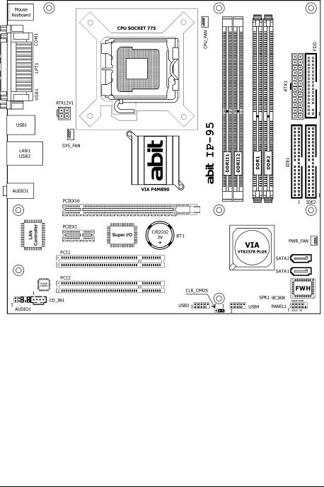
1.2 Motherboard Layout
1-2 |
IP-95 |
1.3 Choosing a Computer Chassis
•Choose a chassis big enough to install this motherboard.
•As some features for this motherboard are implemented by cabling connectors on the motherboard to indicators and switches or buttons on the chassis, make sure your chassis supports all the features required.
•If there is possibility of adopting some more hard drives, make sure your chassis has sufficient power and space for them.
•Most chassis have alternatives for I/O shield located at the rear panel. Make sure the I/O shield of the chassis matches the I/O port configuration of this motherboard. You can find an I/O shield specifically designed for this motherboard in its package.
1.4 Installing Motherboard
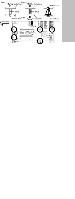
Most computer chassis have a base with many mounting holes to allow the motherboard to be securely attached, and at the same time, prevent the system from short circuits. There are two ways to attach the motherboard to the chassis base: (1) with studs, or (2) with spacers.
Basically, the best way to attach the board is with studs. Only if you are unable to do this should you attach the board with spacers. Line
up the holes on the board with the mounting holes on the chassis. If the holes line up and there are screw holes, you can attach the board with studs. If the holes line up and there are only slots, you can only attach with spacers. Take the tip of the spacers and insert them into the slots. After doing this to all the slots, you can slide the board into position aligned with slots. After the board has been positioned, check to make sure everything is OK before putting the chassis back on.
Always power off the computer and unplug the AC power cord before adding or removing any peripheral or component. Failing to so may cause severe damage to your motherboard and/or peripherals. Plug in the AC power cord only after you have carefully checked everything.
To install this motherboard: |
|
|
1. |
Locate all the screw holes on the |
|
|
motherboard and the chassis base. |
|
2. |
Place all the studs or spacers needed on |
panel. |
|
the chassis base and have them tightened. |
|
|
|
|
3. |
Face the motherboard’s I/O ports toward |
rear |
|
the chassis’s rear panel. |
|
|
|
|
4. |
Line up all the motherboard’s screw holes |
chassis’s |
|
have them tightened. |
|
|
with those studs or spacers on the chassis. |
|
5. |
Install the motherboard with screws and |
|
|
To prevent shorting the PCB circuit, |
the |
|
||
|
please REMOVE the metal studs or |
Face |
|
spacers if they are already fastened |
|
|
|
|
|
on the chassis base and are without |
|
|
mounting-holes on the motherboard |
|
|
to align with. |
|
|
|
|
IP-95 |
1-3 |
|
Setup Hardware
1.5 Checking Jumper Settings
• |
For a 2-pin jumper, plug the |
|
|
|
|
jumper cap on both pins will |
|
|
|
|
make it CLOSE (SHORT). |
|
|
|
|
Remove the jumper cap, or |
|
|
|
|
plug it on either pin |
|
|
|
|
(reserved for future use) will |
|
|
|
|
leave it at OPEN position. |
SHORT |
OPEN |
OPEN |
|
|
|
|
|
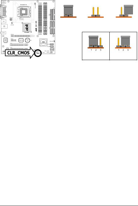
•For 3-pin jumper, pin 1~2 or pin 2~3 can be shorted by plugging the jumper cap in.
Pin 1~2 SHORT Pin 2~3 SHORT
1.5.1 CMOS Memory Clearing Header and Backup Battery
The time to clear the CMOS memory occurs when (a) the CMOS data becomes corrupted, (b) you forgot the supervisor or user password preset in the BIOS menu,
(c) you are unable to boot-up the system because the CPU ratio/clock was incorrectly set in the BIOS menu, or (d) whenever there is modification on the CPU or memory modules.
This header uses a jumper cap to clear the CMOS memory and have it reconfigured to the default values stored in BIOS.
•Pins 1 and 2 shorted (Default): Normal operation.
•Pins 2 and 3 shorted:
Clear CMOS memory.
To clear the CMOS memory and load in the default values:
1.Power off the system.
2.Set pin 2 and pin 3 shorted by the jumper cap. Wait for a few seconds. Set the jumper cap back to its default settings --- pin 1 and pin 2 shorted.
3.Power on the system.
4.For incorrect CPU ratio/clock settings in the BIOS, press <Del> key to enter the BIOS setup menu right after powering on system.
5.Set the CPU operating speed back to its default or an appropriate value.
6.Save and exit the BIOS setup menu.
1-4 |
IP-95 |
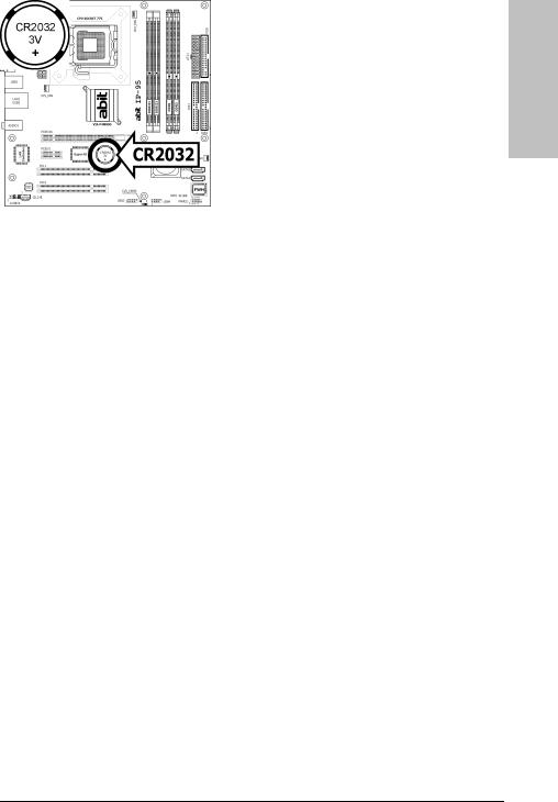
CMOS Backup Battery:
An onboard battery saves the CMOS memory to keep the BIOS information stays on even after disconnected your system with power source. Nevertheless, this backup battery exhausts after some five years. Once the error message like “CMOS BATTERY HAS FAILED” or “CMOS checksum error” displays on monitor, this backup battery is no longer functional and has to be renewed.
To renew the backup battery:
1.Power off the system and disconnect with AC power source.
2.Remove the exhausted battery.
3.Insert a new CR2032 or equivalent battery. Pay attention to its polarity. The “+” side is its positive polarity.
4.Connect AC power source and power on the system.
5.Enter the BIOS setup menu. Reconfigure the setup parameters if necessary.
CAUTION:
Danger of explosion may arise if the battery is incorrectly renewed.
Renew only with the same or equivalent type recommended by the battery manufacturer.
Dispose of used batteries according to the battery manufacturer’s instructions.
Setup Hardware
IP-95 |
1-5 |
1.6 Connecting Chassis Components
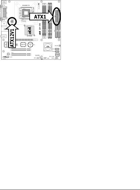
1.6.1 ATX Power Connectors
These connectors provide the connection from an ATX power supply. As the plugs from the power supply fit in only one orientation, find the correct one and push firmly down into these connectors.
ATX 24-Pin Power Connector:
The power supply with 20-pin or 24-pin cables can both be connected to this 24-pin connector. Connect from pin-1 for either type. However, a 20-pin power supply may cause the system unstable or even unbootable for the sake of insufficient electricity. A minimum power of 300W or higher is recommended.
ATX 12V 4-Pin Power Connector:
This connector supplies power to CPU. The system will not start without connecting power to this one.
1-6 |
IP-95 |
1.6.2 Front Panel Switches & Indicators Headers
This header is used for connecting switches and LED indicators on the chassis front panel.
Watch the power LED pin position and orientation. The mark “+” align to the pin in the figure below stands for positive polarity for the LED connection. Please pay attention when connecting these headers. A wrong orientation will only cause the LED not lighting, but a wrong connection of the switches could cause system malfunction.
Setup Hardware
|
Pin |
Definition |
Pin |
Definition |
|
|
|
|
|
|
1 |
HD LED + |
2 |
Message LED + |
|
|
|
|
|
|
3 |
HD LED - |
4 |
Message LED - |
|
|
|
|
|
|
5 |
RESET |
6 |
Power Switch |
|
|
|
|
|
|
7 |
RESET |
8 |
Power Switch |
|
|
|
|
|
|
9 |
Reserved |
|
|
|
|
|
|
|
IP-95 |
1-7 |
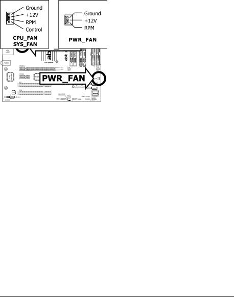
1.6.3 FAN Power Connectors
These connectors each provide power to the cooling fans installed in your system.
•CPU_FAN: CPU Fan Power Connector
•SYS_FAN: System Fan Power Connector
•PWR_FAN: Auxiliary Fan Power Connector
These fan connectors are not jumpers. DO NOT place jumper caps on these connectors.
1-8 |
IP-95 |
Loading...