


Foreword
Foreword
Thank you for purchasing the AB-PX5/AX5/TX5 as the heart of your computer’s system. We hope this instruction booklet will enable you to install PX5/AX5/TX5 in your system safely and without any errors. Although you may be familiar with some of the concepts we will explain, please read over them again to avoid any problems.
1.The motherboard in most PCs use many connecting cables to connect peripherals to the main unit. The important thing to remember is that these cables all have a
‘direction’. Later in the chapter, we will talk more about the definition of connecting cables and the method of installation. Please pay special attention to our prompts. Because we are using the exclusive ABIT SOFTMENUä technology to modify the motherboard , the jumper is not required anymore. We also use simple and easy to understand software design to complete this task. Because of this, you can install the motherboard directly into the system. However, we still suggest you first carry out a simple test before you install the motherboard inside the computer.
2.In this booklet, we will write out in full any new technical words we encounter for the first time and use their contractions thereafter.
3.If, when you are installing the CPU problems occur and there is no way to solve them, we suggest you first clear the CMOS information (refer to Chapter 2). If you still have problems, contact us.
4.How to perform a simple basic test? It’s simple. Place the mother board on a flat insulated surface (like the packaging the motherboard came in). Plug the CPU into
Part No:MN-096-2C1-41 |
Rev:1.21 |
the ZIF socket (if you are installing a fan, install it on top). Plug DRAM module in and then plug the keyboard in. Plug in the electrical cord (ensure electrical supply is turned off when doing this) and pay attention to polarity (refer to Chapter 2). Plug in the display card and plug the 15 Pin D-Sub monitor signal connector into the display card. Make sure the connections are correct and secure and then turn on the power source for the monitor and then the main power supply. If a picture appears on the monitor, congratulations, the basic test has been successful. Finally, good luck with the complete installation.
Computers – Things to Know!
CMOS (Complementary Metal-Oxide Semiconductor)
Maybe you’ve heard of CMOS DATA quite a bit but have never seen it. What exactly is CMOS? Is it important? Well, if it wasn’t important, you would never had heard of it. CMOS basically stores or saves the parameters you assign the BIOS (Basic Input Output System) with in memory. This memory or SRAM can be both read from and written to but it needs battery power to avoid losing this information when the computer is turned off. When the batteries go flat or you need to swap batteries, you may not remember the parameters you set. To avoid this, we recommend you record these parameters or stick them to your hard drive for easy reference.

Table of Contents
|
Foreword |
|
Chapter 1 |
Introduction of AX5/PX5/TX5 Features |
|
¬ AX5 |
............................................................................................ |
1-2 |
• Specifications......................................................................... |
1-2 |
|
• Layout ......................................................................diagram |
1-4 |
|
- PX5............................................................................................. |
|
1-5 |
• Specifications......................................................................... |
1-5 |
|
• Layout ......................................................................diagram |
1-7 |
|
® TX5............................................................................................. |
|
1-8 |
• Specifications......................................................................... |
1-8 |
|
• Layout ....................................................................diagram |
1-11 |
|
¯ System ................................................................block diagram |
1-12 |
|
Chapter 2 |
Installing the Mainboard |
|
¬ Installing .........................................the Mainboard to the Casing |
2-3 |
|
- Standard ......................................................External Connectors |
2-4 |
|
® Jumpers ................................................................and Switches |
2-12 |
|
¯ Presentation ....................................and Installation of the CPU |
2-13 |
|
° Installing .........System Memory ¡i DRAM Memory ¡j |
2-16 |
|
Chapter 3 |
Introduction of BIOS |
|
¬ CPU .............................Setup ¡i CPU SOFT MENU™ ¡j |
3-3 |
|
- Standard ......................................................CMOS Setup Menu |
3-9 |
|
® BIOS .......................................................Features Setup Menu |
3-11 |
|
¯ Chipset ....................................................Features Setup Menu |
3-17 |
|
° Power ...............................................Management Setup Menu |
3-19 |
|
± PCI & .........................................................Onboard I/O Setup |
3-23 |
|
² Load ..................................................................BIOS Defaults |
3-28 |
|
Part No:MN-096-2C1-41 |
Rev:1.21 |
³ Load Setup Defaults .................................................................. |
3-28 |
´ Password Setting ....................................................................... |
3-29 |
µ IDE HDD Auto Detection ......................................................... |
3-30 |
Appendix A Quick Installation
Appendix B Intel Pentium CPUs
Appendix C AMD-K5 CPUs
Appendix D Cyrix/IBM 6x86 CPUs
Appendix E General Discussion about HDD Installation
Appendix F Technical Support
Appendix G Flash BIOS User Instructions
Appendix H How to install Ultra DMA/33 drive
Appendix I How to install the PCI bridge driver for 430TX chipset

Introduction of AX5/PX5/TX5 Features |
1-1 |
Chapter 1 Introduction of
AX5/PX5/TX5 Features
The AX5/PX5/TX5 have been especially designed for File server, Workstation and Professional users. It can support a wide range of processors, including all Intel CPUs (P54C) and Intel CPUs with MMX (P55C), as well as all AMD-K5/K6 and Cyrix 6x86/6x86L/6x86MX CPUs. It also takes into account, as much as possible, all future CPUs.
The AX5/PX5/TX5 uses SOFT MENU™ technology, which means that all the parameters can be configured without using DIP switches or jumpers. The configuration is entirely achieved through a “Soft Switch” that allows the user to set CPU speed and operating voltage with ease.
The AX5/PX5/TX5 uses Intel 430TX series chipsets, and has 512K Level- 2 Pipeline Burst SRAM on board.
168-pin DIMM ( Dual In-Line Memory Module ) slots and 72-pin SIMM (Single In-Line Memory Module )slots meet the requirements for all memory configurations required by high level computing. The 168-pin DIMM slots support traditional Fast Page and EDO ( Extended Data Out ) DRAM as a memory standard for next generation 64-bit systems. The 168-pin DIMM slots have been reserved to meet requirements for both present and future upgrades.
The AX5/PX5/TX5 also provides two Universal Serial Bus (USB) ports and meets the Concurrent PCI ( Peripheral Component Interconnect ) Rev. 2.1 standard. It also supports IDE interface for Fast HDD (Mode 0~4) and Ultra DMA/33 ( Direct Memory Access ), as well as IDE Bus Master. These features also meet present and future interface standards and needs.
System BIOS features include Plug-and-Play (PnP), Advanced Configuration Power Interface (ACPI), the newest Desktop Management Interface (DMI), as well as AX5/PX5/TX5’s unique CPU operating frequency and voltage setup feature in order to meet modern computing demands.

1-2 |
Chapter 1 |
¬AX5 nSpecifications
1.Support ATX power supply.
2.CPU frequency and voltage setup with CPU “SOFT MENU™ ”
•Setup of the mainboard’s frequency and voltage without DIP Switches or Jumpers.
•Modification of CPU operating voltage and frequency by the BIOS Setup .
3.Uses ZIF CPU Socket 7 for easy CPU installation
•Support switching power for CPU to get more stable environment
•Supports Intel CPUs:
1)Pentium® 100MHz to 200MHz
2)Pentium® processor with MMXTM technology 166MHz to 233MHz
•Supports AMD CPUs: 1)AMD-K5™ PR100 ~ PR166.
2)AMD-K6TM 166MHz ~ 233MHz.
•Supports Cyrix/IBM CPUs:
1)Cyrix 6x86TM P120+ ~ P200+.
2)Cyrix 6x86LTM P150+ ~ P200+.
3)Cyrix 6x86MXTM PR150 ~ PR233 .
4.Chipset
•Intel 430TX chipset
•Supports standard version PCI 2.1
5.L2 Cache Memory
•512K of cache memory (Pipeline Burst SRAM)
6.System DRAM
•Four 72-pin SIMM sockets: support FP and EDO DRAM
•Three 168-pin DIMM sockets: support FP, EDO and Synchronous DRAM (SDRAM)
•DIMM sockets use PC modules (3.3V Unbuffered DRAM)
•Up to 256MB memory configuration possible
Introduction of AX5/PX5/TX5 Features |
1-3 |
7. System BIOS
•AWARD BIOS
•Supports Plug-and-Play (PnP)
•Supports Advanced Configuration Power Interface (ACPI)
•Supports Desktop Management Interface (DMI)
8.Multi I/O features
•Two Universal Serial Bus (USB) ports
•Four fast IDE channels (PIO mode 0~4, Ultra “DMA/33” and Bus Master)
•One standard EPP/ECP parallel port and two 16550A serial ports
•Two floppy disk drive connectors (FDD) (360K, 720K, 1.2M, 1.44M and 2.88M)
•Support PS/2 type mouse
9.Other features
•Standard ATX architecture dimensions
•Four ISA bus slots and four PCI bus slots
•Supports 3-MODE for a special Japanese floppy disk drive
•Supports two bootable hard disks--able to run two different operating systems
•Supports IDE interface CD-ROM and LS-120 type floppy disk drive (Boot only)
Note: All brand names and trademarks are the property of their respective owners. *Specifications and information contained in this catalogue are subject to change without notice.
1-4 |
Chapter 1 |
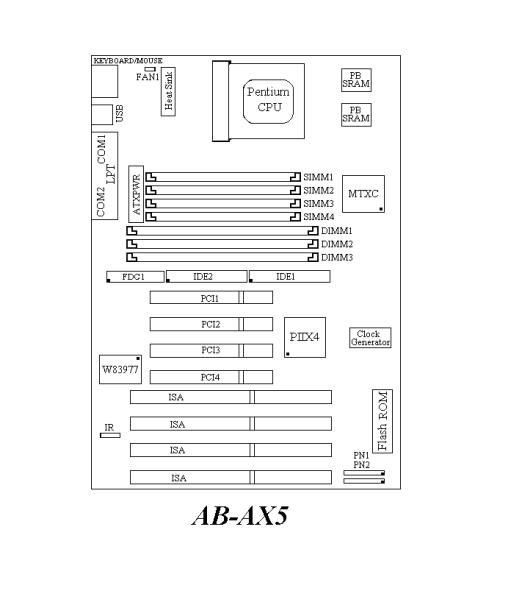
n Layout diagram
Fig 1-1 Layout diagram

Introduction of AX5/PX5/TX5 Features |
1-5 |
- PX5
nSpecifications
1. Supports AT |
power supply |
2. CPU frequency and voltage setup with CPU “SOFT MENU™ ”
•Setup of the mainboard’s frequency and voltage without DIP Switches or Jumpers.
•Modification of CPU operating voltage and frequency by the BIOS Setup.
3.Uses ZIF CPU Socket 7 for easy CPU installation
•Support switching power for CPU to get more stable environment
•Supports Intel CPUs:
1)Pentium® 100MHz to 200MHz .
2 ) Pentium® processor with MMXTM technology 166MHz to
233MHz
•Supports AMD CPUs:
1 ) AMD-K5™ PR100 ~ PR166.
2)AMD-K6TM 166MHz ~ 233MHz.
•Supports Cyrix/IBM CPUs:
1)Cyrix 6x86TM P120+ ~ P200+.
2)Cyrix 6x86LTM P150+ ~ P200+.
3)Cyrix 6x86MXTM PR150 ~ PR233 .
4.Chipset
•Intel 430TX chipset
•Supports standard version PCI 2.1
5.L2 Cache Memory
•512K of cache memory (Pipeline Burst SRAM)
6.System DRAM
•Two 72-pin SIMM sockets: support FP and EDO DRAM
•Two 168-pin DIMM sockets: support FP, EDO and Synchronous DRAM (SDRAM)
•DIMM sockets use PC modules (3.3V Unbuffered DRAM)
•Up to 256MB memory configuration possible
1-6 |
Chapter 1 |
7. System BIOS
•AWARD BIOS
•Supports Plug-and-Play (PnP)
•Supports Advanced Configuration Power Interface (ACPI)
•Supports Desktop Management Interface (DMI)
8.Multi I/O features
•Two Universal Serial Bus (USB) ports
•Four fast IDE channels (PIO mode 0~4, Ultra “DMA/33” and Bus Master)
•One standard EPP/ECP parallel port and two 16550 serial ports
•Two floppy disk drive connectors (FDD) (360K, 720K, 1.2M, 1.44M and 2.88M)
•Support PS/2 type mouse
9.Other features
•Standard AT architecture dimensions
•Four ISA bus slots and four PCI bus slots
•Supports 3-MODE for a special Japanese floppy disk drive
•Supports two bootable hard disks--able to run two different operating systems
•Supports IDE interface CD-ROM and LS-120 type floppy disk drive (Boot only)
No e: Al b a d * pe if ca io s no ic .
am s nd tr de |
ar |
s re th |
nd in or at on |
co |
ta ne i |
p op rt o |
t ei |
r sp ct ve ow |
er . |
t is ca al |
gu |
a e ub ec t |
c an e it ou |

Introduction of AX5/PX5/TX5 Features |
1-7 |
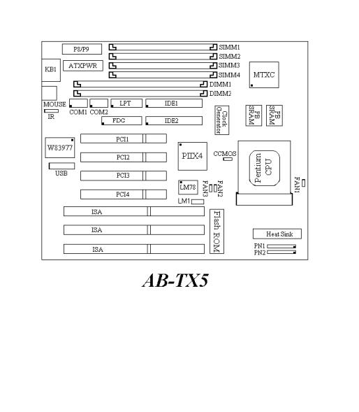
n Layout diagram
Fig 1-2 Layout diagram

1-8 |
Chapter 1 |
® TX5
nSpecifications
1.Supports AT and ATX power supply
2.CPU frequency and voltage setup with CPU “SOFT MENU™ ”
•Setup of the mainboard’s frequency and voltage without DIP Switches or Jumpers.
•Modification of CPU operating voltage and frequency by the BIOS Setup.
3.Uses ZIF CPU Socket 7 for easy CPU installation
•Support switching power for CPU to get more stable environment
•Supports Intel CPUs:
1)Pentium® 120MHz to 200MHz
2 ) Pentium® processor with MMXTM technology 166MHz to
233MHz
•Supports AMD CPUs:
1 ) AMD-K5™ PR120 to PR166.
2)AMD-K6TM 166MHz ~ *266MHz .
•Supports Cyrix/IBM CPUs:
1)Cyrix 6x86TM P150+ ~ P200+.
2)Cyrix 6x86LTM P150+ ~ P200+.
3)Cyrix 6x86MXTM PR150 ~ PR233 .
*Supports 2.2 Volts Vcore voltage.( Starting form Rev 1.2), Can support AMD-K6TM 266 MHz processor.
4.Chipset
•Intel 430TX chipset
•Supports standard version PCI 2.1
5.L2 Cache Memory
•512K of cache memory (Pipeline Burst SRAM)
6.System DRAM
•Four 72-pin SIMM sockets: support FP and EDO DRAM
•Two 168-pin DIMM sockets: support FP, EDO and Synchronous DRAM (SDRAM)
•DIMM sockets use PC modules (3.3V Unbuffered DRAM)
Introduction of AX5/PX5/TX5 Features |
1-9 |
•Up to 256MB memory configuration possible
7.System BIOS
•AWARD BIOS
•Supports Plug-and-Play (PnP)
•Supports Advanced Configuration Power Interface (ACPI)
•Supports Desktop Management Interface (DMI)
8.Multi I/O features
•Two Universal Serial Bus (USB) ports
•Four fast IDE channels (PIO mode 0~4, Ultra “DMA/33” and Bus Master)
•One standard EPP/ECP parallel port and two 16550 serial ports
•Two floppy disk drive connectors (FDD) (360K, 720K, 1.2M, 1.44M and 2.88M)
•Support PS/2 type mouse
9.Other features
•Standard AT architecture dimensions
•Three ISA bus slots and four PCI bus slots
•Supports 3-MODE for a special Japanese floppy disk drive
•Supports two bootable hard disks--able to run two different operating systems
•Support monitor for system temperature, Fan running and voltage, also support
•Support special interface EISCA to monitor system environment
•Supports IDE interface CD-ROM and LS-120 type floppy disk drive (Boot only)
1-10 |
Chapter 1 |
Computer |
The EISCA(Enhanced Intelligent System Cooler Architecture) |
Knowledge |
is a specially designed 12-pin interface which integrates the |
|
Mainboard and the CPU cooling system. This system is a total |
|
solution for PC system heat sink problems. |
|
Due to increasing CPU speed, which causes higher |
|
temperatures, finding ways to effectively deal with CPU |
|
temperatures is becoming a more and more crucial problem. |
|
Effectively and precisely determining CPU temperature was a |
|
very important requirement. The area directly under the CPU |
|
socket is the location on the mainboard. closest to the CPU, |
|
and heat is conducted away from this area through air |
|
circulation. Determining temperature change under |
|
these circumstances is very imprecise, as it only allows us to |
|
detect large changes in temperature. In addition, because the |
|
air under the CPU socket is confined to this area, the sensor |
|
cannot detect temperature in real time. Tests have proven that |
|
under such circumstances, even after 5 minutes the sensor |
|
located under the CPU socket is unable to detect real |
|
temperature change, so it can not meet the requirements for |
|
thermal problems. |
|
In EISCA architecture, the thermal sensor is located at the |
|
heat-sink. In this way, the sensor is able to detect CPU |
|
temperature in real time and more precisely. The EISCA |
|
monitors voltage, fan speed and fan on/off control to meet the |
|
important specifications. |
Note: All brand names and trademarks are the property of their respective owners. *Specifications and information contained in this catalogue are subject to change without notice.
Introduction of AX5/PX5/TX5 Features |
1-11 |
n Layout diagram
Fig 1-3 Layout diagram
1-12 |
Chapter 1 |
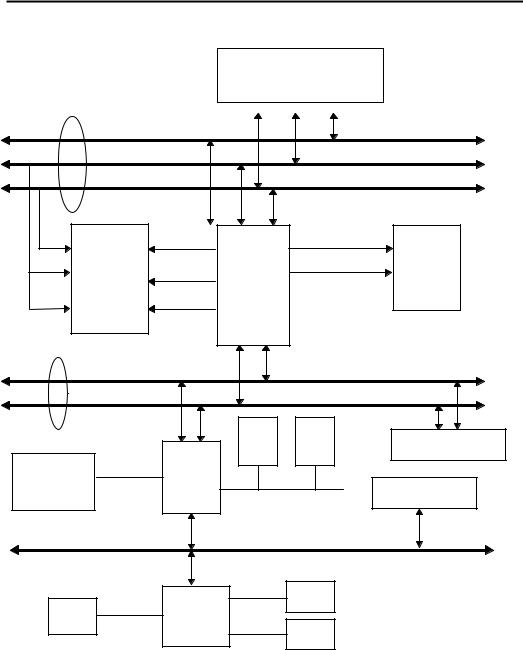
¯ System block diagram
Pentiumä Processor
Host BUS |
|
|
3.3V |
|
|
|
|
|
|
||
|
|
|
|
Control |
|
|
|
|
|
Address |
|
|
|
|
|
Data |
|
Second |
|
|
|
|
|
Level Cache |
|
|
|
||
CACHE |
Ctrl |
|
Addr |
Main |
|
|
|
Ctrl |
|||
(SRAM) |
Tag Ctrl |
MTXC |
Memory |
||
|
|||||
|
|
|
|||
|
TIO[0..7] |
|
|
(DRAM) |
|
|
|
|
|
||
TAG |
|
|
|
|
|
PCI BUS |
|
Control |
|
|
|
||
|
|
Address/Data |
|
Fast |
USB |
USB |
|
|
PCI Device(s) |
||
IDE |
1 |
2 |
|
CD ROM & |
PIIX4 |
|
|
Hard Disk |
ISA Device(s) |
||
|
|||
|
Universal Serial Bus |
||
ISA BUS |
|
|
|
Winbond LPT
Serial
W83977
FDC
Fig. 1-4 System block diagram

Installing the Mainboard |
2-1 |
Chapter 2 Installing the
Mainboard
This AX5/PX5/TX5 mainboard not only provides all standard equipment for classic personal computers, but also provides great flexibility for meeting future upgrade demands. This chapter will introduce step by step all the standard equipment and will also present, as completely as possible future upgrade capabilities. This mainboard is able to support all Intel Pentium including P55C with MMX, Cyrix 6x86, 6x86L, 6x86MX and AMD-K5/K6 processors now on the market. (For details, see specifications in Chapter 1.) However, we cannot guarantee that the description given in this manual on the circuitry of your mainboard will work for processors not listed in Chapter 1. For example, the operating voltage of Cyrix’s next generation CPUs is unknown
at the present time. |
Thus we were not able to include these specifications in |
your motherboard. |
We will supply further information about CPU support |
when new CPUs arrive on the market.
This chapter is organized according the following features: ΠInstalling the Mainboard to the Casing
•Standard external connectors Ž Jumpers and switches
•Presentation and Installing of the CPU. º Installing the system memory.
NNNN
Before proceeding with the installation
Before installing the mainboard please be sure to turn off or disconnect the power supply unit. Before making any modifications to the hardware configuration of the mainboard, the power supply to any areas of the mainboard you plan to modify should be turned off to avoid unnecessary damage to the hardware.

2-2 |
Chapter 2 |
&
Us r ri nd y ns ru ti ns
Our objective is to enable the novice computer user to perform the installation by themselves. We have attempted to write this document in a very clear, concise and descriptive manner to help overcome any obstacles you may face
during installation. |
Please read our instructions carefully and follow them |
carefully step-by-step. |
|

Installing the Mainboard |
2-3 |
¬ Installing the Mainboard to the Casing
Most computer cases will have a base on which there will be many mounting holes that allows the mainboard to be securely attached and at the same time, prevents short circuits.
There are two ways to attach the mainboard to the base. •with spacers
•or with bolts
In principle, the best way to attach the motherboard is with bolts, and only if you are unable to do this should you attach the board with spacers. Take a careful look at the mainboard and you will see many mounting holes on it. Line these holes up with the mounting holes on the base. If the holes line up, and there are screw holes this means you can attach the mainboard with bolts. If the holes line up and there are only slots, this means you can only attach the mainboard with spacers. Take the tip of the spacers and insert it into the slots. After doing this to all the slots, you can slide the mainboard into position aligned with the slots. After the mainboard has been positioned, check to make sure everything is OK before putting the casing back on.
Note: If the mainboard has mounting holes, but don’t line up with the holes on the base and their are no slots to attach the spacers, don’t panic, you can still attach the spacers to the mounting holes. Just cut the spacers (along the dotted line) (the spacer may be a little hard so be careful of our hands). In this way you can still attach the mainboard to the base without worrying about short circuits.
|
Why is it that Cyrix is always raised in relation to IBM in books? In |
|
Computer |
fact, these two 6*86 CPUs (limited to the 6*86 series) are basically |
|
the same thing. Because Cyrix does not have its own production line, |
||
Knowledge |
||
it has contracted IBM to manufacture their 6*86 CPUs for them. |
||
|
However, IBM has stipulated that the Cyrix CPUs they produce |
|
|
have both the Cyrix and IBM mark printed on it. |
2-4 |
Chapter 2 |
- Standard External Connectors
Inside the case of any computer several cables and plugs have to be connected. These cables and plugs are usually connected one-by-one to connectors located on the mainboard. You need to carefully pay attention to any connection orientation the cables may have and, if any, notice the position of the first pin of the connector. In the explanations that follow, we will describe the significance of the first pin.
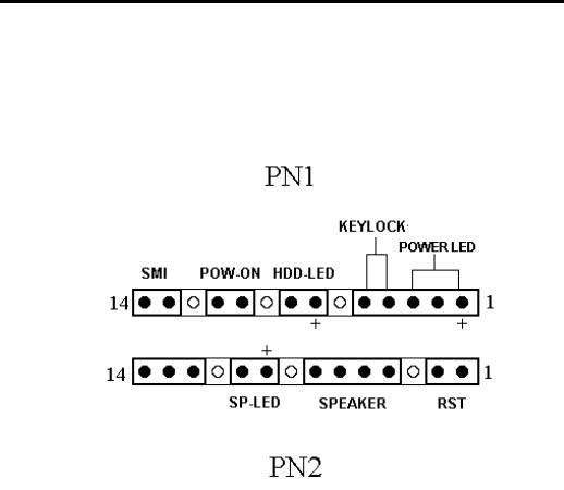
PN1 - Keylock connector Please pay attention to pin position and orientation
This connector has a specific orientation. Connect the five-thread keylock connector cable to the PN1 connector pins on the mainboard.
Pin number |
Name or significance of signal |
|
1 |
+5VDC |
power LED |
|
|
|
2 |
No connection |
power LED |
3 |
Ground |
power LED |
4 |
Keyboard inhibit Signal |
key lock |
5 |
Ground |
key lock |
Computer
Knowledge
The “keylock switch” is used to lock the computer’s keyboard. This disables the keyboard so that unauthorized persons cannot use it. When this function is in use, you will need to use the unlock key to activate the keyboard.
Installing the Mainboard |
2-5 |
PN1 - Power ON/OFF connectors
There is no specific orientation. Since most cases do not support this feature, most of you ignore this instruction. If the case support this kind of power switch connector, please connect this connector into Mainboard. In this case, you have to use ATX type power supply to get this function.
Pin number |
Name or significance of the signal |
10 |
Power on/off |
11 |
Ground |
PN1 - SMI Switch |
|
|
|
||
There is no specific orientation. |
Connect the two-thread cable to the PN1 |
||||
connector pins |
on the mainboard. |
Since |
most cases do not support this |
||
feature, most of you ignore this instruction. |
Furthermore, this feature is not |
||||
necessary as it is already a part of the mainboard. |
|||||
|
|
|
|
|
|
Pin number |
|
Name or significance of signal |
|
|
|
13 |
|
+5VDC |
|
|
|
14 |
|
suspend |
|
|
|
PN1 - HDD LED connector |
|
This connector has a specific orientation. |
Connect the two-thread IDE LED |
connector cable attached to the case to the IDE LED connector on the mainboard.
Pin number |
Name or significance of signal |
7 |
LED’s Cathode |
8 |
LED’s Anode |

2-6 |
Chapter 2 |
PN2 - Speaker connector |
|
|
|
There is no specific orientation. |
Connect the four-thread speaker cable to |
||
the PN2 connector pins on the mainboard. |
|||
|
|
|
|
Pin number |
Name or significance of signal |
|
|
4 |
+5VDC |
|
|
5 |
Ground |
|
|
6 |
Ground |
|
|
7 |
Sound Signal |
|
|
PN2 - Hardware Reset connectors
There is no specific orientation. Connect the two-thread hardware reset cable to the PN2 connector pins on the mainboard.
Pin number |
Name or significance of signal |
1 |
Hardware reset signal |
2 |
Ground |
PN2 - Sleep LED connector
This connector has a specific orientation. Connect the two-thread Sleep LED connector cable attached to the case to the Sleep LED connector on the mainboard.
Pin number |
Name or significance of signal |
9 |
LED’s Cathode |
10 |
LED’s Anode |
FAN1 - CPU Fan power connector (AX5/PX5)
This has a specific orientation. Connect the three-threads CPU fan cable to the FAN1 connector.
Pin number |
Name of the signal or signification |
1 |
Ground |
2 |
+12V |
3 |
Ground |

Installing the Mainboard |
2-7 |
FAN1 - CPU Fan power connector (TX5)
This has a specific orientation. Connect the three-threads CPU fan cable to the FAN1 connector.
If, at the bottom of the fan, there are only two threads, just connect them to PIN2 and PIN3.
Pin number |
Name of the signal or signification |
1 |
Sensor signal |
2 |
+12V |
3 |
Control on/off |
IR - Infrared remote Connectors Watch the pin number and the orientation
This has a specific orientation. Your mainboard supports this feature, but you must buy the infrared remote device as an option.
(AX5) :
Pin number |
Name of the signal or signification |
1 |
+5VDC |
2 |
No connection |
3 |
Transmit data |
4 |
Ground |
5 |
Receive data |
(PX5 TX5) :
Pin number |
Name of the signal or signification |
1 |
+5VDC |
2 |
No connection |
3 |
Receive data |
4 |
Ground |
5 |
Transmit data |

2-8 |
Chapter 2 |
ATXPWR - ATX Power input Connectors
These have a specific orientation. The three warning marks indicate that if you make a mistake in pin number or connection orientation, you could destroy your equipment. During installation, you just need to connect to the correct pins and in the correct orientation, and to connect connector of the power supply unit to the connector on the mainboard.
Pin number |
Name of the signal or |
Pin number |
Name of the signal or |
|
signification |
signification |
|||
|
|
|||
1 |
+3.3VDC |
11 |
+3.3VDC |
|
2 |
+3.3VDC |
12 |
-12VDC |
|
3 |
Ground |
13 |
Ground |
|
4 |
+5VDC |
14 |
PS_ON |
|
5 |
Ground |
15 |
Ground |
|
6 |
+5VDC |
16 |
Ground |
|
7 |
Ground |
17 |
Ground |
|
8 |
POWERGOOD |
18 |
-5VDC |
|
9 |
+5VDC |
19 |
+5VDC |
|
10 |
+12VDC |
20 |
+5VDC |
P8/P9 - AT Power input Connectors (the AX5 do not support this connector)
These have a specific orientation. The three warning marks indicate that if you make a mistake in pin number or connection orientation, you could destroy your equipment. During installation, you just need to connect to the correct pins and in the correct orientation, and to connect connectors P8 and P9 of the power supply unit to the connectors on the mainboard.
Pin number |
Name of the signal or |
Pin number |
Name of the signal or |
|
signification |
signification |
|||
|
|
|||
1 |
POWERGOOD |
7 |
Ground |
|
2 |
+5VDC |
8 |
Ground |
|
3 |
+12VDC |
9 |
-5VDC |
|
4 |
-12VDC |
10 |
+5VDC |
|
5 |
Ground |
11 |
+5VDC |
|
6 |
Ground |
12 |
+5VDC |
Installing the Mainboard |
2-9 |
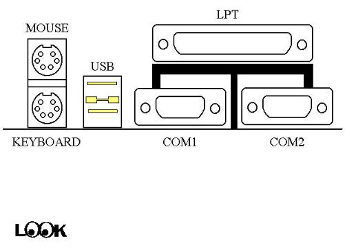
Mechanics of Mouse/Keyboard/USB/COM1/COM2/LPT |
(AX5) |
Mouse - PS/2 Mouse connector Watch the pin number and the orientation
This has a specific orientation. Connect the six-threads PS/2 Mouse cable provided to the connector on the mainboard.
Pin number |
Name of the signal or signification |
1 |
Mouse data |
2 |
No connection |
3 |
Ground |
4 |
+5VDC |
5 |
Ground |
6 |
Mouse clock |
Computer knowledge
The “PS/2 Mouse Port” is different from COM1 or COM2 serial ports to which you can also connect a Mouse. This mainboard features an extra PS/2 Mouse port, so when you buy a mouse, be sure that it is a PS/2 Mouse before connecting it to this port. But if you cannot find any PS/2 Mouse, you can still use COM1 or COM2 to connect a serial mouse to your computer.
Keyboard - PS/2 Keyboard Connector |
(AX5) |
2-10 |
Chapter 2 |
This has an orientation pin. Connect your keyboard connector to the connector on the mainboard.
Pin number |
Name of the signal or signification |
1 |
Keyboard data |
2 |
No connection |
3 |
Ground |
4 |
+5VDC |
5 |
Ground |
6 |
Keyboard clock |
KB1 - Keyboard Connector (PX5/TX5)
This has an orientation pin. Connect your keyboard connector to the connector on the mainboard.
Pin number |
Name of the signal or signification |
1 |
Keyboard clock |
2 |
Keyboard data |
3 |
No connection |
4 |
Ground |
5 |
+5VDC |
I/O Port connectors Watch the pin number and the orientation
Connector name |
Pin number |
Name of the peripheral connected |
IDE 1 |
40 |
IDE Channel 1 |
|
|
|
IDE 2 |
40 |
IDE Channel 2 |
|
|
|
FDC |
34 |
Floppy Disk connector |
|
|
|
LPT |
26 |
Parallel port connector |
|
|
|
COM1 |
10 |
Serial port COM1 connector |
|
|
|
COM2 |
10 |
Serial port COM2 connector |
|
|
|
USB |
16 |
Universal Serial Bus connector |
|
|
|
Installing the Mainboard |
2-11 |
LM1 - Enhanced Intelligent System Coller Architecture Connectors (TX5)
This has an orientation pin. Connect your EISCA connector to the connector on the mainboard.
Pin number |
Name of the signal or signification |
1 |
I2C Serial Bus Clock |
2 |
I2C Serial Bus Data |
3 |
Set for active low for wire interrupt line |
4 |
Key |
5 |
+5VDC |
6 |
Alarm speaker output |
7 |
Ground |
8 |
Vcore detect |
9 |
fanl sensor input |
10 |
Vio detect |
11 |
fan2 sensor input |
12 |
+12VDC |

2-12 |
Chapter 2 |
® Jumpers and Switches
CCMOS : Delete the contents of the CMOS
This jumper is set on pins 1 and 2 at the factory, in order for the computer to function normally, so please do not change this setting. The main feature of this jumper is to solve situations where the computer crashes due to improper usage. For instance:
•You have forgotten the password you set.
•You have changed inappropriately the settings in the BIOS menu.
•You want to change the version of flash BIOS.
All these errors are very serious, you must avoid them. But if you have made one of these errors, this jumper can save your life. First turn off the power supply and open the computer case, than place the jumper on pins 2 and 3 in order to save your computer. But if you use your computer normally, you should not need to use this feature.
After you have deleted the CMOS information, the computer is saved, but you still have to go back to the BIOS Setup menu, and reset one by one all the specifications: CPU, date, hour, FDD and HDD parameters. etc., before your computer will get back into normal operation.

Installing the Mainboard |
2-13 |
¯ Presentation and Installation of the CPU
Jumperless Mainboard (Mainboard with no DIP Switch or Jumper)
The AX5/PX5/TX5 mainboard can be installed with CPU without the hardware setting of the CPU.
On other boards, when you want to install the CPU, you have, more or less, to setup some jumpers or DIP switches. With the AX5/PX5/TX5 mainboard, you will not need to adjust any jumper or switch. The CPU speed and model is set up by software, in order to allow the user to complete setup and installation procedures easily. After you have inserted the CPU on the CPU socket, you can close the computer case and turn the computer on. You just need to enter the CPU SOFT MENU™ located in the BIOS Setup, and to setup the speed and the voltage of the CPU to compete the installation. Even if you don’t need to setup any switch, we recommend you to read our presentation of the CPUs, it will be useful information for you.
Since 1996, every two or three months, Intel adds new models to the Pentium CPU series. That is why the CPU market is filled with a lot of different models and brands. All CPUs have different electrical specifications. That’s why installing a CPU is becoming more and more complex. You can’t help that, because everybody wants to be able to upgrade its hardware. So, you have to take a bit of time to read this section, in order to be able to install a cheaper and better processor.
The AX5/PX5/TX5 mainboard does not only support all the CPUs listed in the specifications, but also has reserved several circuits in order to be able to support future processors. But before we go further in our presentation, we must clarify that “we have only tested the CPUs listed in Chapter 1”, we cannot guarantee that this board will be able to support future products, because we cannot forecast future developments. But we will do our best to support any possible CPU.
2-14 |
Chapter 2 |
Related terminology :
External clock
Also referred to as the external CPU clock, or “Bus clock”, it is the input clock of the CPU. For instance, Intel Pentium P90, P120 and P150 all have a 60MHz external CPU clock, but have different internal clock multiplier factors.
Clock multiplier factor
The real operation clock within the CPU is the multiple of the external clock. We refer to this factor as the clock multiplier factor. The four factors possible are 1.5, 2, 2.5 and 3. The factor differs from one CPU to another. For instance, the Intel Pentium 166 CPU has a 66MHz external clock, with a multiplier factor of 2.5, so that the speed of the internal clock is 66MHz x 2.5.
Internal clock
Also referred to as the real internal CPU clock, it is the actual internal operating clock of the CPU. The Internal Clock is a multiple of the external clock and of the clock multiplier factor. For instance, the Intel Pentium 90 CPU has a 60MHz external clock and its clock multiplier factor is 1.5; the Intel Pentium P133 CPU has a 66MHz external clock and its clock multiplier factor is 2.
Internal CPU clock = clock multiplier factor * external CPU clock
AT Bus clock
Also referred to as ISA SPEED, or AT CLOCK, or even ISA Bus clock. Ten years ago, the original specification of AT Bus clock installed in the first generation PC/AT computers was 8MHz, this means that there are some interface cards which can only work at 8MHz. In order to guarantee compatibility with older hardware, we still support 8MHz AT Bus clock, but if your interface card is newer or faster, you can choose a higher speed for the AT Bus clock, in order to increase the transmission rate of the interface cards. But we recommend you not to be too ambitious. An 8MHz setup ensures maximum compatibility.
 Loading...