


July 2016
Version 1.6.0

| 1
Copyright
Copyright © 2016 4RF Limited. All rights reserved.
This document is protected by copyright belonging to 4RF Limited and may not be reproduced or republished in whole or part in any form without the prior written permission of 4RF Limited.
Trademarks
Aprisa and the 4RF logo are trademarks of 4RF Limited.
Windows is a registered trademark of Microsoft Corporation in the United States and other countries. Java and all Java-related trademarks are trademarks or registered trademarks of Sun Microsystems, Inc. in the United States and other countries. All other marks are the property of their respective owners.
Disclaimer
Although every precaution has been taken preparing this information, 4RF Limited assumes no liability for errors and omissions, or any damages resulting from use of this information. This document or the equipment may change, without notice, in the interests of improving the product.
RoHS and WEEE Compliance
The Aprisa SR+ is fully compliant with the European Commission’s RoHS (Restriction of Certain Hazardous Substances in Electrical and Electronic Equipment) and WEEE (Waste Electrical and Electronic Equipment) environmental directives.
Restriction of hazardous substances (RoHS)
The RoHS Directive prohibits the sale in the European Union of electronic equipment containing these hazardous substances: lead, cadmium, mercury, hexavalent chromium, polybrominated biphenyls (PBBs), and polybrominated diphenyl ethers (PBDEs).
4RF has worked with its component suppliers to ensure compliance with the RoHS Directive which came into effect on the 1st July 2006.
End-of-life recycling programme (WEEE)
The WEEE Directive concerns the recovery, reuse, and recycling of electronic and electrical equipment. Under the Directive, used equipment must be marked, collected separately, and disposed of properly.
4RF has instigated a programme to manage the reuse, recycling, and recovery of waste in an environmentally safe manner using processes that comply with the WEEE Directive (EU Waste Electrical and Electronic Equipment 2002/96/EC).
4RF invites questions from customers and partners on its environmental programmes and compliance with the European Commission’s Directives (sales@4RF.com).
Aprisa SR+ User Manual 1.6.0 PO

2 |
Compliance General
The Aprisa SR+ radio predominantly operates within frequency bands that require a site license be issued by the radio regulatory authority with jurisdiction over the territory in which the equipment is being operated.
It is the responsibility of the user, before operating the equipment, to ensure that where required the appropriate license has been granted and all conditions attendant to that license have been met.
Changes or modifications not approved by the party responsible for compliance could void the user’s authority to operate the equipment.
Equipment authorizations sought by 4RF are based on the Aprisa SR+ radio equipment being installed at a fixed restricted access location and operated in point-to-multipoint or point-to-point mode within the environmental profile defined by EN 300 019, Class 3.4. Operation outside these criteria may invalidate the authorizations and / or license conditions.
The term ‘Radio’ with reference to the Aprisa SR+ User Manual, is a generic term for one end station of a point-to-multipoint Aprisa SR+ network and does not confer any rights to connect to any public network or to operate the equipment within any territory.
Compliance European Telecommunications Standards Institute
The Aprisa SR+ radio is designed to comply with the European Telecommunications Standards Institute (ETSI) specifications as follows:
|
|
12.5 kHz and 25 kHz |
50 kHz Channel |
|||
|
|
Channel |
|
|
|
|
|
|
|
|
|
|
|
Radio performance |
|
EN 300 113-2 |
|
EN 302 561 (pending) |
||
|
|
|
|
|
|
|
EMC |
|
EN 301 489-1 and 5 |
|
|
|
|
|
|
|
|
|
|
|
Environmental |
|
EN 300 019, Class 3.4 |
|
|
||
|
|
Ingress Protection IP51 |
|
|
||
|
|
|
|
|
|
|
Safety |
|
EN 60950-1:2006 |
|
|
|
|
|
|
Class 1 division 2 for hazardous locations |
|
|||
|
|
|
|
|
|
|
|
|
|
|
|
||
Frequency band |
Channel size |
|
Power input |
Notified |
||
|
|
|
|
|
|
body |
|
|
|
|
|
|
|
135-175 MHz |
12.5 kHz, 25 kHz |
|
13.8 VDC |
|
|
|
|
|
|
|
|
|
|
215-240 MHz |
12.5 kHz, 20 kHz, |
|
13.8 VDC |
|
|
|
|
25 kHz, 50 kHz |
|
|
|
|
|
|
|
|
|
|
|
|
320-400 MHz |
12.5 kHz, 20 kHz, |
|
13.8 VDC |
|
|
|
|
25 kHz, 50 kHz |
|
|
|
|
|
|
|
|
|
|
|
|
400-470 MHz |
12.5 kHz, 20 kHz, |
|
13.8 VDC |
|
|
|
|
25 kHz, 50 kHz |
|
|
|
|
|
|
|
|
|
|
|
|
450-520 MHz |
12.5 kHz, 25 kHz, 50 kHz |
|
13.8 VDC |
|
|
|
|
|
|
|
|
|
|
Aprisa SR+ User Manual 1.6.0 PO

| 3
Compliance Federal Communications Commission
The Aprisa SR+ radio is designed to comply with the Federal Communications Commission (FCC) specifications as follows:
Radio |
|
47CFR part 24, part 27, part 90 and part 101 Private Land |
||||
|
|
Mobile Radio Services |
|
|||
|
|
|
|
|
|
|
EMC |
|
47CFR part |
15 Radio Frequency Devices, EN 301 489-1 and |
|||
|
|
5 |
|
|
|
|
|
|
|
|
|
|
|
Environmental |
|
EN 300 019, Class 3.4 |
|
|||
|
|
Ingress Protection IP51 |
|
|||
|
|
|
|
|
|
|
Safety |
|
EN 60950-1:2006 |
|
|
||
|
|
Class 1 division 2 for hazardous locations |
||||
|
|
|
|
|
|
|
|
|
|
|
|
||
Frequency Band * |
Channel size |
Power |
Authorization |
FCC ID |
||
|
|
|
input |
|
|
|
|
|
|
|
|
|
|
135-175 MHz |
15 kHz, 30 kHz |
13.8 |
VDC |
Part 90 |
UIPSQ135M150 |
|
|
|
|
|
|
|
|
215-240 MHz |
12.5 kHz, 15 kHz, |
13.8 |
VDC |
Part 90 |
UIPSQ215M141 |
|
|
25 kHz, 50 kHz |
|
|
|
|
|
|
|
|
|
|
|
|
400-470 MHz |
12.5 kHz, 25 kHz, |
13.8 |
VDC |
Part 90 |
UIPSQ400M1311 |
|
|
50 kHz |
|
|
|
|
|
|
|
|
|
|
|
|
450-520 MHz |
12.5 kHz, 25 kHz |
13.8 |
VDC |
Part 90 |
Pending |
|
|
|
|
|
|
||
757-758 MHz and |
12.5 kHz, 25 kHz, |
13.8 VDC |
Part 27 |
Pending |
||
787-788 MHz |
50 kHz |
|
|
|
|
|
|
|
|
|
|
|
|
896-902 MHz |
12.5 kHz, 25 kHz, |
13.8 |
VDC |
Part 24 / |
UIPSQ896M141 |
|
|
50 kHz |
|
|
Part 90 / |
|
|
|
|
|
|
|
Part 101 |
|
|
|
|
|
|
|
|
928-960 MHz |
12.5 kHz, 25 kHz, |
13.8 |
VDC |
Part 24 / |
UIPSQ928M141 |
|
|
50 kHz |
|
|
Part 90 / |
|
|
|
|
|
|
|
Part 101 |
|
|
|
|
|
|
|
|
NOTE: This equipment has been tested and found to comply with the limits for a Class A digital device, pursuant to part 15 of the FCC Rules. These limits are designed to provide reasonable protection against harmful interference when the equipment is operated in a commercial environment. This equipment generates, uses, and can radiate radio frequency energy and, if not installed and used in accordance with the instruction manual, may cause harmful interference to radio communications. Operation of this equipment in a residential area is likely to cause harmful interference in which case the user will be required to correct the interference at his own expense.
* The Frequency Band is not an indication of the exact frequencies approved by FCC.
Aprisa SR+ User Manual 1.6.0 PO

4 |
Compliance Industry Canada
The Aprisa SR+ radio is designed to comply with Industry Canada (IC) specifications as follows:
Radio |
|
|
RSS-119 / RSS-134 |
|
|
||
|
|
|
|
|
|
|
|
EMC |
|
|
This Class A digital apparatus complies with Canadian |
||||
|
|
|
standard ICES-003. |
|
|
||
|
|
|
Cet appareil numérique de la classe A est conforme à la |
||||
|
|
|
norme NMB-003 du Canada. |
|
|||
|
|
|
|
|
|
|
|
Environmental |
|
|
EN 300 019, Class 3.4 |
|
|||
|
|
|
Ingress Protection IP51 |
|
|||
|
|
|
|
|
|
|
|
Safety |
|
|
EN 60950-1:2006 |
|
|
||
|
|
|
Class 1 division 2 for hazardous locations |
||||
|
|
|
|
|
|
|
|
|
|
|
|
|
|
|
|
Frequency Band * |
Channel size |
|
Power |
|
Authorization |
IC |
|
|
|
|
|
input |
|
|
|
|
|
|
|
|
|
|
|
135-175 MHz |
15 kHz, 30 kHz |
|
13.8 VDC |
|
RSS-119 |
6772A-SQ135M150 |
|
|
|
|
|
|
|
|
|
215-240 MHz |
12.5 kHz, 15 kHz, |
|
13.8 VDC |
|
RSS-119 |
Pending |
|
|
25 kHz, 50 kHz |
|
|
|
|
|
|
|
|
|
|
|
|
|
|
400-470 MHz |
12.5 kHz, 25 kHz, |
|
13.8 VDC |
|
RSS-119 |
6772A-SQ400M1311 |
|
|
50 kHz |
|
|
|
|
|
|
|
|
|
|
|
|
|
|
896-902 MHz |
12.5 kHz, 25 kHz, |
|
13.8 VDC |
|
RSS-119 and |
Pending |
|
|
50 kHz |
|
|
|
RSS-134 |
|
|
|
|
|
|
|
|
|
|
928-960 MHz |
12.5 kHz, 25 kHz, |
|
13.8 VDC |
|
RSS-119 and |
Pending |
|
|
50 kHz |
|
|
|
RSS-134 |
|
|
|
|
|
|
|
|
|
|
* The Frequency Band is not an indication of the exact frequencies approved by IC.
Compliance Brazil
Este produto será comercializado no Brasil com as configurações abaixo:
Faixa de frequência: 406,10 a 413,05, 423,05 a 430 MHz, 451,00625 a 452,0065 MHz, 459 a 460 MHz, 461,0025 a 462,00625 MHz e 469 a 470 MHz.
Modulações: QPSK, 16QAM e 64QAM
BW: 12,5 e 25 KHz.
Aprisa SR+ User Manual 1.6.0 PO

| 5
Compliance Hazardous Locations Notice
This product is suitable for use in Class 1, Division 2, Groups A - D hazardous locations or non-hazardous locations.
The following text is printed on the Aprisa SR+ fascia:
WARNING: EXPLOSION HAZARD - Do not connect or disconnect while circuits are live unless area is known to be non-hazardous.
The following text is printed on the Aprisa SR+ where the end user is in Canada:
AVERTISSEMENT: RISQUE D'EXPLOSION - Ne pas brancher ou débrancher tant que le circuit est sous tension, à moins qu'il ne s'agisse d'un emplacement non dangereux.
The USB service ports are not to be used unless the area is known to be non-hazardous.
Compliance IEEE 1613 class 2
Users requiring compliance to IEEE 1613 class 2 should use screened cables and connectors to connect to the serial ports.
Aprisa SR+ User Manual 1.6.0 PO

6 |
RF Exposure Warning
WARNING:
The installer and / or user of Aprisa SR+ radios shall ensure that a separation distance as given in the following table is maintained between the main axis of the terminal’s antenna and the body of the user or nearby persons.
Minimum separation distances given are based on the maximum values of the following methodologies:
1.Maximum Permissible Exposure non-occupational limit (B or general public) of
47 CFR 1.1310 and the methodology of FCC’s OST/OET Bulletin number 65.
2.Reference levels as given in Annex III, European Directive on the limitation of exposure of the general public to electromagnetic fields (0 Hz to 300 GHz) (1999/519/EC). These distances will ensure indirect compliance with the requirements of EN 50385:2002.
Frequency (MHz) |
Maximum Power |
Maximum Antenna |
Minimum Separation |
|
(dBm) Note 1 |
Gain (dBi) |
Distance |
|
|
|
(m) |
|
|
|
|
135 |
+ 37 |
15 |
3.5 |
|
|
|
|
175 |
+ 37 |
15 |
3.5 |
|
|
|
|
215 |
+ 37 |
15 |
3.5 |
|
|
|
|
240 |
+ 37 |
15 |
3.5 |
|
|
|
|
320 |
+ 37 |
15 |
3.5 |
|
|
|
|
400 |
+ 37 |
15 |
3.0 |
|
|
|
|
450 |
+ 37 |
15 |
3.0 |
|
|
|
|
470 |
+ 37 |
15 |
3.0 |
|
|
|
|
520 |
+ 37 |
15 |
3.0 |
|
|
|
|
757 |
+ 37 |
18 |
3.5 |
|
|
|
|
788 |
+ 37 |
18 |
3.5 |
|
|
|
|
896 |
+ 37 |
28 |
10.0 |
|
|
|
|
902 |
+ 37 |
28 |
10.0 |
|
|
|
|
928 |
+ 37 |
28 |
9.5 |
|
|
|
|
960 |
+ 37 |
28 |
9.5 |
|
|
|
|
Note 1: The Peak Envelope Power (PEP) at maximum set power level is +41 dBm.
Aprisa SR+ User Manual 1.6.0 PO

|
|
Contents | 7 |
Contents |
|
|
1. |
Getting Started ........................................................................ |
13 |
2. |
Introduction............................................................................ |
15 |
|
About This Manual............................................................................... |
15 |
|
What It Covers ............................................................................ |
15 |
|
Who Should Read It ...................................................................... |
15 |
|
Contact Us................................................................................. |
15 |
|
What’s in the Box ............................................................................... |
15 |
|
Aprisa SR+ Accessory Kit ................................................................ |
16 |
|
Aprisa SR+ CD Contents.................................................................. |
16 |
|
Software ............................................................................ |
16 |
|
Documentation .................................................................... |
16 |
3. |
About the Radio ....................................................................... |
17 |
|
The 4RF Aprisa SR+ Radio ...................................................................... |
17 |
|
Product Overview ............................................................................... |
18 |
|
Network Coverage and Capacity ....................................................... |
18 |
|
Automatic Registration .................................................................. |
18 |
|
Remote Messaging........................................................................ |
18 |
|
Store and Forward Repeater............................................................ |
19 |
|
Repeater Packet Forwarding..................................................... |
19 |
|
Repeater Messaging ............................................................... |
22 |
|
Peer To Peer Communication Between Remote Radios...................... |
23 |
|
Product Features ................................................................................ |
24 |
|
Functions .................................................................................. |
24 |
|
Security .................................................................................... |
25 |
|
Performance .............................................................................. |
26 |
|
Usability ................................................................................... |
26 |
|
System Gain vs FEC Coding ............................................................. |
27 |
|
Architecture...................................................................................... |
28 |
|
Product Operation........................................................................ |
28 |
|
Physical Layer............................................................................. |
28 |
|
Data Link Layer / MAC layer ............................................................ |
29 |
|
Channel Access .................................................................... |
29 |
|
Hop by Hop Transmission......................................................... |
30 |
|
Adaptive Coding and Modulation ................................................ |
30 |
|
Network Layer ............................................................................ |
31 |
|
Packet Routing..................................................................... |
31 |
|
Static IP Router .................................................................... |
32 |
|
Bridge Mode with VLAN Aware .................................................. |
35 |
|
VLAN Bridge Mode Description .................................................. |
36 |
|
Avoiding Narrow Band Radio Traffic Overloading.................................... |
38 |
|
Interfaces......................................................................................... |
40 |
|
Antenna Interface ........................................................................ |
40 |
|
Ethernet Interface ....................................................................... |
40 |
|
RS-232 / RS-485 Interface............................................................... |
40 |
|
USB Interfaces ............................................................................ |
40 |
|
Protect Interface ......................................................................... |
40 |
|
Alarms Interface.......................................................................... |
40 |
Aprisa SR+ User Manual 1.6.0 PO

8 | |
Contents |
|
|
Front Panel Connections ....................................................................... |
41 |
|
LED Display Panel ............................................................................... |
42 |
|
Normal Operation ........................................................................ |
42 |
|
Single Radio Software Upgrade......................................................... |
43 |
|
Network Software Upgrade ............................................................. |
43 |
|
Test Mode ................................................................................. |
44 |
|
Network Management .......................................................................... |
45 |
|
Hardware Alarm Inputs / Outputs ............................................................ |
46 |
|
Alarm Input to SNMP Trap............................................................... |
46 |
|
Alarm Input to Alarm Output ........................................................... |
46 |
|
Aprisa SR Alarm Input to Aprisa SR+ Alarm Output .................................. |
46 |
4. |
Implementing the Network.......................................................... |
47 |
|
Network Topologies ............................................................................. |
47 |
|
Point-To-Point Network .......................................................... |
47 |
|
Point-to-Multipoint Network ..................................................... |
47 |
|
Point-to-Multipoint with Repeater 1............................................ |
47 |
|
Point-to-Multipoint with Repeater 2............................................ |
47 |
|
Initial Network Deployment ................................................................... |
48 |
|
Install the Base Station .................................................................. |
48 |
|
Installing the Remote Stations ......................................................... |
48 |
|
Install a Repeater Station ............................................................... |
48 |
|
Network Changes ................................................................................ |
49 |
|
Adding a Repeater Station .............................................................. |
49 |
|
Adding a Remote Station ................................................................ |
49 |
5. |
Preparation ............................................................................ |
51 |
|
Bench Setup...................................................................................... |
51 |
|
Path Planning .................................................................................... |
52 |
|
Antenna Selection and Siting ........................................................... |
52 |
|
Base or Repeater Station ......................................................... |
52 |
|
Remote station .................................................................... |
53 |
|
Antenna Siting ..................................................................... |
54 |
|
Coaxial Feeder Cables ................................................................... |
55 |
|
Linking System Plan ...................................................................... |
55 |
|
Site Requirements............................................................................... |
56 |
|
Power Supply.............................................................................. |
56 |
|
Equipment Cooling ....................................................................... |
56 |
|
Earthing and Lightning Protection ..................................................... |
57 |
|
Feeder Earthing.................................................................... |
57 |
|
Radio Earthing ..................................................................... |
57 |
6. |
Installing the Radio ................................................................... |
58 |
|
Mounting.......................................................................................... |
58 |
|
Required Tools............................................................................ |
58 |
|
DIN Rail Mounting ........................................................................ |
59 |
|
Rack Shelf Mounting ..................................................................... |
60 |
|
Wall Mounting............................................................................. |
61 |
|
Installing the Antenna and Feeder Cable .................................................... |
62 |
|
Connecting the Power Supply ................................................................. |
63 |
|
External Power Supplies................................................................. |
63 |
|
Spare Fuses................................................................................ |
64 |
|
Additional Spare Fuses............................................................ |
65 |
Aprisa SR+ User Manual 1.6.0 PO
|
|
Contents | 9 |
7. |
Managing the Radio ................................................................... |
67 |
|
SuperVisor ........................................................................................ |
67 |
|
PC Requirements for SuperVisor ....................................................... |
68 |
|
Connecting to SuperVisor ............................................................... |
69 |
|
Management PC Connection ..................................................... |
70 |
|
PC Settings for SuperVisor ....................................................... |
71 |
|
Login to SuperVisor................................................................ |
75 |
|
Logout of SuperVisor .............................................................. |
76 |
|
SuperVisor Page Layout........................................................... |
77 |
|
SuperVisor Menu ................................................................... |
79 |
|
SuperVisor Menu Access .......................................................... |
80 |
|
SuperVisor Menu Items ........................................................... |
82 |
|
Standard Radio............................................................................ |
83 |
|
Terminal ............................................................................ |
83 |
|
Radio .............................................................................. |
101 |
|
Serial .............................................................................. |
122 |
|
Ethernet .......................................................................... |
137 |
|
IP................................................................................... |
147 |
|
QoS ................................................................................ |
160 |
|
Security ........................................................................... |
182 |
|
Maintenance ..................................................................... |
204 |
|
Events ............................................................................. |
222 |
|
Software .......................................................................... |
234 |
|
Monitoring ........................................................................ |
253 |
|
Network Status .................................................................. |
271 |
|
Protected Station ...................................................................... |
278 |
|
Terminal .......................................................................... |
279 |
|
Radio .............................................................................. |
285 |
|
Ethernet .......................................................................... |
287 |
|
IP................................................................................... |
288 |
|
Security ........................................................................... |
292 |
|
Maintenance ..................................................................... |
294 |
|
Events ............................................................................. |
302 |
|
Software .......................................................................... |
305 |
|
Command Line Interface ..................................................................... |
322 |
|
Connecting to the Management Port ................................................ |
322 |
|
CLI Commands .......................................................................... |
325 |
|
Viewing the CLI Terminal Summary........................................... |
326 |
|
Changing the Radio IP Address with the CLI ................................. |
326 |
8. |
In-Service Commissioning .......................................................... |
327 |
|
Before You Start............................................................................... |
327 |
|
What You Will Need.................................................................... |
327 |
|
Antenna Alignment............................................................................ |
328 |
|
Aligning the Antennas ................................................................. |
328 |
Aprisa SR+ User Manual 1.6.0 PO

10 |
| Contents |
|
9. |
Product Options ...................................................................... |
329 |
|
Data Interface Ports .......................................................................... |
329 |
|
Full Duplex Base Station ..................................................................... |
329 |
|
Protected Station ............................................................................. |
330 |
|
Protected Ports ......................................................................... |
331 |
|
Operation................................................................................ |
331 |
|
Switch Over ...................................................................... |
331 |
|
Switching Criteria ............................................................... |
332 |
|
Monitored Alarms................................................................ |
333 |
|
Configuration Management .................................................... |
334 |
|
Hardware Manual Lock ......................................................... |
335 |
|
Remote Control .................................................................. |
335 |
|
L2 / L3 Protection Operation .................................................. |
336 |
|
Hot-Swappable................................................................... |
336 |
|
Antenna and Duplexer Options ................................................ |
337 |
|
Installation .............................................................................. |
339 |
|
Mounting .......................................................................... |
339 |
|
Cabling ............................................................................ |
340 |
|
Power ............................................................................. |
342 |
|
Alarms............................................................................. |
342 |
|
Maintenance ............................................................................ |
343 |
|
Changing the Protected Station IP Addresses ............................... |
343 |
|
Creating a Protected Station .................................................. |
344 |
|
Replacing a Protected Station Faulty Radio ................................. |
344 |
|
Replacing a Faulty Power Supply.............................................. |
345 |
|
Replacing a Faulty Protection Switch ........................................ |
345 |
|
Spares .................................................................................... |
345 |
|
Data Driven Protected Station............................................................... |
346 |
|
Operation................................................................................ |
346 |
|
Over The Air Compatibility .................................................... |
346 |
|
Switch Over ...................................................................... |
347 |
|
Configuration Management .................................................... |
347 |
|
Power ............................................................................. |
347 |
|
Installation .............................................................................. |
348 |
|
Mounting .......................................................................... |
348 |
|
Cabling ............................................................................ |
348 |
|
Duplexer Kits................................................................................... |
349 |
|
Radio Duplexer Kits .................................................................... |
349 |
|
Protected Station Duplexer Kits...................................................... |
351 |
|
USB RS-232 / RS-485 Serial Port............................................................. |
353 |
|
USB RS-232 / RS-485 operation....................................................... |
353 |
|
USB RS-232 Cabling Options........................................................... |
354 |
|
USB RS-485 Cabling Options........................................................... |
354 |
|
USB Retention Clip .............................................................. |
355 |
Aprisa SR+ User Manual 1.6.0 PO

|
|
Contents | 11 |
10. |
Maintenance .......................................................................... |
357 |
|
No User-Serviceable Components ........................................................... |
357 |
|
Software Upgrade ............................................................................. |
358 |
|
Network Software Upgrade ........................................................... |
358 |
|
Non-Protected Network Upgrade Process.................................... |
358 |
|
Protected Network Upgrade Process ......................................... |
360 |
|
Single Radio Software Upgrade....................................................... |
362 |
|
File Transfer Method............................................................ |
362 |
|
USB Boot Upgrade Method ..................................................... |
363 |
|
Software Downgrade ............................................................ |
363 |
|
Protected Station Software Upgrade ................................................ |
364 |
11. |
Interface Connections............................................................... |
365 |
|
RJ45 Connector Pin Assignments............................................................ |
365 |
|
Ethernet Interface Connections ............................................................. |
365 |
|
RS-232 Serial Interface Connections........................................................ |
366 |
|
RS-232 Pinout .................................................................... |
366 |
|
RS-232 Customer Cable Wiring ................................................ |
366 |
|
RS-232 RJ45 LED Indicators .................................................... |
366 |
|
Alarm Interface Connections ................................................................ |
367 |
|
Protection Switch Remote Control Connections .......................................... |
367 |
12. Alarm Types and Sources........................................................... |
368 |
|
|
Alarm Types .................................................................................... |
368 |
|
Alarm Events ............................................................................ |
369 |
|
Informational Events................................................................... |
374 |
13. |
Specifications ......................................................................... |
375 |
|
RF Specifications .............................................................................. |
375 |
|
Frequency Bands ....................................................................... |
375 |
|
Channel Sizes ........................................................................... |
376 |
|
Receiver ................................................................................. |
389 |
|
Transmitter ............................................................................. |
392 |
|
Modem ................................................................................... |
393 |
|
Data Payload Security ................................................................. |
393 |
|
Interface Specifications ...................................................................... |
394 |
|
Ethernet Interface ..................................................................... |
394 |
|
RS-232 Asynchronous Interface....................................................... |
395 |
|
Hardware Alarms Interface ........................................................... |
396 |
|
Protection Switch Specifications ..................................................... |
396 |
|
Power Specifications.......................................................................... |
397 |
|
Power Supply............................................................................ |
397 |
|
Power Consumption .................................................................... |
398 |
|
Power Dissipation ...................................................................... |
398 |
|
General Specifications........................................................................ |
399 |
|
Environmental .......................................................................... |
399 |
|
Mechanical .............................................................................. |
399 |
|
Compliance.............................................................................. |
400 |
Aprisa SR+ User Manual 1.6.0 PO

12 | Contents |
|
|
14. |
Product End Of Life.................................................................. |
401 |
|
End-of-Life Recycling Programme (WEEE) ................................................. |
401 |
|
The WEEE Symbol Explained .......................................................... |
401 |
|
WEEE Must Be Collected Separately ................................................. |
401 |
|
YOUR ROLE in the Recovery of WEEE................................................ |
401 |
|
EEE Waste Impacts the Environment and Health .................................. |
401 |
15. |
Copyrights ............................................................................. |
402 |
16. |
Abbreviations ......................................................................... |
403 |
Aprisa SR+ User Manual 1.6.0 PO

Getting Started | 13
1.Getting Started
This section is an overview of the steps required to commission an Aprisa SR+ radio network in the field:
Phase 1: |
Pre-installation |
|
|
|
|
|
|
|
|
1. |
Confirm path planning. |
Page |
52 |
|
|
|
|
|
|
2. |
Ensure that the site preparation is complete: |
Page |
55 |
|
|
|
Power requirements |
|
|
|
|
Tower requirements |
|
|
|
Environmental considerations, for example, temperature control |
|
|
|
|
|
Mounting space |
|
|
|
|
|
|
|
|
|
|
||
Phase 2: |
Installing the radios |
|
|
|
|
|
|
|
|
1. |
Mount the radio. |
Page |
58 |
|
|
|
|
|
|
2. |
Connect earthing to the radio. |
Page |
57 |
|
|
|
|
|
|
3. |
Confirm that the: |
|
|
|
|
Antenna is mounted and visually aligned |
|
|
|
|
Feeder cable is connected to the antenna |
|
|
|
|
Feeder connections are tightened to recommended level |
|
|
|
|
Tower earthing is complete |
|
|
|
|
|
|
|
|
4. |
Install lightning protection. |
Page |
57 |
|
|
|
|
|
|
5. |
Connect the coaxial jumper cable between the lightning protection and the |
Page |
62 |
|
|
radio antenna port. |
|
|
|
|
|
|
|
|
6. |
Connect the power to the radio. |
Page |
63 |
|
|
|
|
|
|
Aprisa SR+ User Manual 1.6.0 PO

14 | Getting Started
Phase 3: |
Establishing the link |
|
|
|
|
|
|
|
|
1. |
If radio’s IP address is not the default IP address (169.254.50.10 with a subnet |
Page |
322 |
|
|
mask of 255.255.0.0) and you don’t know the radio’s IP address see ‘Command |
|
|
|
|
Line Interface’ on page 322. |
|
|
|
|
|
|
|
|
2. |
Connect the Ethernet cable between the radio’s Ethernet port and the PC. |
|
|
|
|
|
|
|
|
3. |
Confirm that the PC IP settings are correct for the Ethernet connection: |
Page |
71 |
|
|
|
IP address |
|
|
|
|
Subnet mask |
|
|
|
|
Gateway IP address |
|
|
|
|
|
|
|
4. |
Open a web browser and login to the radio. |
Page |
75 |
|
|
|
|
|
|
5. |
Set or confirm the RF characteristics: |
Page |
103 |
|
|
TX and RX frequencies |
|
|
|
|
|
TX output power |
|
|
|
|
|
|
|
6. |
Compare the actual RSSI to the expected RSSI value (from your path planning). |
Page |
44 |
|
|
|
|
|
|
7. |
Align the antennas. |
Page |
328 |
|
|
|
|
|
|
8. |
Confirm that the radio is operating correctly; the OK, MODE and AUX LEDs are |
|
|
|
|
green. |
|
|
|
|
|
|
|
|
Aprisa SR+ User Manual 1.6.0 PO

Introduction | 15
2.Introduction
About This Manual
What It Covers
This user manual describes how to install and configure an Aprisa SR+ point-to-multipoint digital radio network.
It specifically documents an Aprisa SR+ radio running system software version 1.6.0 .
It is recommended that you read the relevant sections of this manual before installing or operating the radios.
Who Should Read It
This manual has been written for professional field technicians and engineers who have an appropriate level of training and experience.
Contact Us
If you experience any difficulty installing or using Aprisa SR+ after reading this manual, please contact Customer Support or your local 4RF representative.
Our area representative contact details are available from our website:
4RF Limited
26 Glover Street, Ngauranga
PO Box 13-506
Wellington 6032
New Zealand
support@4rf.com |
|
Web site |
www.4rf.com |
Telephone |
+64 4 499 6000 |
Facsimile |
+64 4 473 4447 |
Attention |
Customer Services |
What’s in the Box
Inside the box you will find:
One Aprisa SR+ radio fitted with a power connector.
One Aprisa SR+ Accessory kit containing the following:
Aprisa SR+ CD
Aprisa SR+ Quick Start Guide
Management Cable
Aprisa SR+ User Manual 1.6.0 PO
16 | Introduction
Aprisa SR+ Accessory Kit
The accessory kit contains the following items:
Aprisa SR+ Quick Start Guide
Aprisa SR+ CD
Management Cable
USB Cable USB A to USB micro B, 1m
Aprisa SR+ CD Contents
The Aprisa SR+ CD contains the following:
Software
The latest version of the radio software (see ‘Software Upgrade’ on page 358)
USB Serial Driver
Web browsers - Mozilla Firefox and Internet Explorer are included for your convenience
Adobe™ Acrobat® Reader® which you need to view the PDF files on the Aprisa SR+ CD
Documentation
User manual - an electronic (PDF) version for you to view online or print
Product collateral - application overviews, product description, quick start guide, case studies, software release notes and technical papers
Aprisa SR+ User Manual 1.6.0 PO

About the Radio | 17
3.About the Radio
The 4RF Aprisa SR+ Radio
The 4RF Aprisa SR+ is a Point-To-Multipoint (PMP) and Point-To-Point (PTP) digital radio providing secure narrowband wireless data connectivity for SCADA, infrastructure and telemetry applications.
The radios carry a combination of serial data and Ethernet data between the base station, repeater stations and remote stations.
A single Aprisa SR+ is configurable as a:
Point-To-Multipoint base station, remote station, repeater station or a base-repeater station
Point-To-Point local or remote radio
Aprisa SR+ User Manual 1.6.0 PO

18 | About the Radio
Product Overview
Network Coverage and Capacity
The Aprisa SR+ has a typical link range of up to 120 km, however, geographic features, such as hills, mountains, trees and foliage, or other path obstructions, such as buildings, will limit radio coverage. Additionally, geography may reduce network capacity at the edge of the network where errors may occur and require retransmission. However, the Aprisa SR+ uses 10W output power and Forward Error Correction (FEC) which greatly improves the sensitivity and system gain performance of the radio resulting in less retries and minimal reduction in capacity.
Ultimately, the overall performance of any specific network will be defined by a range of factors including the RF output power, the modulation used and its related receiver sensitivity, the geographic location, the number of remote stations in the base station coverage area and the traffic profile across the network. Effective network design will distribute the total number of remote stations across the available base stations to ensure optimal geographic coverage and network capacity.
One base station can register and operate with up to 500 remote / repeater stations.
The practical limit of remote / repeater stations that can operate with one base station is determined by a range of factors including the number of services, the packet sizes, the protocols used, the message types and network timeouts.
Automatic Registration
On start-up, the remote station transmits a registration message to the base station which responds with a registration response. This allows the base station to record the details of all the remote stations active in the network.
If a remote station cannot register with the base station after multiple attempts within 10 minutes, it will automatically reboot. If remote is not able to register with base station in 5 attempts, then a ‘Network Configuration Warning’ alarm event will be raised indicating that a remote is not registered with the base station.
If a remote station has registered with the base station but then loses communication, it will automatically reboot within 2 minutes.
Remote Messaging
There are two message types in the Aprisa SR+ network, broadcast messages and unicast messages. Broadcast messages are transmitted by the base station to the remote stations and unicast messages are transmitted by the remote station to the base station. These messages are commonly referred to as uplink (unicast remote to base) and downlink (broadcast base to remote).
All remotes within the coverage area will receive broadcast messages and pass them on to either the Ethernet or serial interface. The RTU determines if the message is intended for it and will accept it or discard it.
Aprisa SR+ User Manual 1.6.0 PO
About the Radio | 19
Store and Forward Repeater
The Aprisa SR+ in Repeater mode is used to link remote stations to the base station when direct communication is not possible due to terrain, distance, fade margin or other obstructions in the network. The following example depicts a repeater on the hill top to allow communication between the base station and the remote stations on the other side of hilly terrain.
Repeater Packet Forwarding
The Aprisa SR+ works in packet Store and Forward (S&F) for simple and low cost repeater network.
Repeater mode is available in both Access Request (AR) and Listen Before Send (LBS/CSMA) MAC operating modes. It allows a radio in Repeater mode to store a received packet and retransmit it.
Single Repeater Single Hop
The following example depicts an Aprisa SR+ single repeater single hop Store and Forward network.
Aprisa SR+ User Manual 1.6.0 PO

20 | About the Radio
Multiple Repeater Single Hop
The following example depicts an Aprisa SR+ multiple repeater single hop store and forward network supporting both overlapping and non-overlapping coverage repeater networks. An overlapped RF coverage area creates radio interference and might affect network performance and reduce throughput, as show in figure (a), where Remote 1 is in overlapped RF coverage with Repeater 1 and Repeater 2.
The Aprisa SR+ functionality allows repeaters in Bridge mode to forward Ethernet packets based on Repeater Network Segment ID. The base station translates the destination address (DA) to the Repeater Network Segment ID. This improves repeater performance by forwarding the packet if the Repeater Network Segment ID belongs to the repeater branch and discards the packet if it doesn’t.
Router mode supports repeater packet forwarding based on IP destination address. This improves repeater performance by forwarding the packet if the IP destination address belongs to the repeater branch and discards the packet if it doesn’t
Aprisa SR+ User Manual 1.6.0 PO
About the Radio | 21
Multiple Repeater Multiple Hop
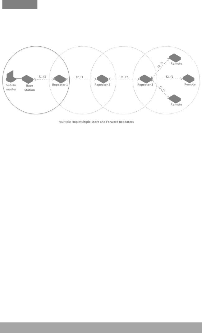
The following example depicts an Aprisa SR+ daisy chain multiple repeater multiple hop store and forward network i.e. multiple hops and multiple repeaters in non-overlapping RF coverage. The Aprisa SR+ daisy chain store and forward repeaters are currently supported in LBS MAC mode only.
In any type of store and forward repeater network base, repeater and remote radios must have their Tx/Rx frequencies sets to match to their appropriate linking devices as shown in the figures.
Note: Frequencies shown in the figures relates to the device on the left where {Tx, Rx} = {fx, fy}. In this example, the Base Station, Repeater 2 and remotes are deployed with Tx=f1 and Rx=f2. On the other hand Repeater 1 and Repeater 3 are deployed with Tx=f2 and Rx=f1, creating the required linking for daisy chain operation.
Aprisa SR+ User Manual 1.6.0 PO

22 | About the Radio
Repeater Messaging
The Aprisa SR+ uses a routed protocol throughout the network whereby messages contain source and destination addresses. The remote and repeater stations will register with a base station. In networks with a repeater, the repeater must register with the base station before the remotes can register with the base station.
Additionally, based on destination address, messages are designated as either a ‘broadcast’ message, (mostly originating from a base station) or a ‘unicast’ message (mostly originating from a remote station).
In a network with a repeater, or multiple repeaters, the base station broadcasts a message which contains a source address and a destination address. The repeater receives the message and recognizes it as a broadcast message, from the destination address and re-broadcasts the message across the network. In IP routing mode all remote stations in the coverage area will receive the message but only the radio with the destination address will act upon the message.
Similarly, the remote station will send a unicast message which contains a unicast destination address (the base station). The repeater will receive this message; recognize the destination address and forward it to the appropriate destination address.
In order to prevent repeater-repeater loops, a detection mechanism of ‘duplicate message’ and use of unicast messaging in remote to base/repeater direction is used.
For example, in the Multiple Repeater Single Hop figure above, the topology is of Base, Repeater 1, Repeater 2 and Remote 1 connected to Repeater 1 in overlapping coverage, where Remote 1 can also hear Repeater 2. When the Base station broadcasts a message, Remote1 will receive this message from both Repeater 1 and Repeater 2 but will drop one of them as ‘duplicate message’. It is possible that Repeater 1, for example, can also hear the broadcast sent out by Repeater 2. In this case, Repeater 1 will drop this broadcast as a ‘duplicate message’.
These phenomena will not happen in the upstream direction as all messages are sent ‘unicast’. Remote 1 will send a packet to Base station, setting the destination address in packet to Base station and ‘next hop’ address in packet to Repeater 1. Thus, only Repeater 1 will forward the packet to Base station and
Repeater 2 will drop the packet as the ‘next hop’ address is not Repeater 2.
Aprisa SR+ User Manual 1.6.0 PO
About the Radio | 23
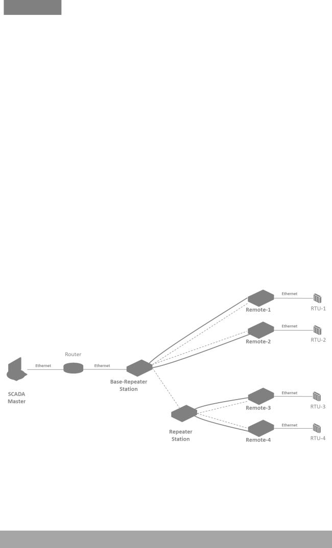
Peer To Peer Communication Between Remote Radios
The Aprisa SR+ peer to peer communication between remote radios is used to enable communication between remote radios via the repeater or base-repeater. It is useful if the SCADA server or base station fails or when in some industries like the water industry, where a reservoir remote station might send a direct message to a valve remote station to close or open the valve without the intervention of the SCADA server.
The Aprisa SR+ has a special operating mode for peer to peer communication between remote radios and requires the following settings:
1.If peer to peer communication between remote radios is required to operate via the base station, then the SuperVisor > Terminal > Operating Mode > Terminal operating mode must be set to ‘BaseRepeater’. Base-Repeater operating mode doesn’t change the Network Radius parameter as the base-repeater is considered to be like a regular base station.
2.The remote radios participating in peer to peer communication must set the SuperVisor > Radio > Channel Setup > Packet Filtering to Disable to allow a repeated packet received from peer to peer remote radios by the repeater or base-repeater to forward the packet to the relevant interface and not to discard it.
3.IP Header Compression must be disabled on all radios (base, repeater, remotes) for this feature to operate correctly (See ‘IP Header Compression Ratio’ on page 119).
4.The Network Repeaters Proximity must be set to ‘Base Repeater’ on all remote radios for this feature to operate correctly (See ‘Network Repeaters Proximity’ on page 89’).
5.Note: In ‘Router Mode’ setup a static route for any required peer to peer path.
The following example depicts peer to peer communication between remote radios via a base-repeater and via a repeater station where remote-1 and remote-2 communicate with each other via the baserepeater station and remote-3 and remote-4 communicate with each other via the repeater station. All the remote radios are configured with packet filtering disabled and all radios in the network are configured with IP header compression ratio disabled.
Note: The Aprisa SR+ network is transparent to the protocol being transmitted; therefore the Packet Filtering parameter is based on the Aprisa SR+ addressing and network protocols, not the user (SCADA, etc.) traffic protocols.
Aprisa SR+ User Manual 1.6.0 PO

24 | About the Radio
Product Features
Functions
Point-to-Point (PTP) or Point-to-Multipoint (PMP) operation
Licensed frequency bands:
VHF 135 |
135-175 MHz |
|
VHF 220 |
215-240 MHz |
|
UHF 320 |
320-400 MHz |
|
UHF 400 |
400-470 MHz |
|
UHF 450 |
450-520 |
MHz |
UHF 700 |
757-758 |
MHz and 787-788 MHz |
UHF 896 |
896-902 |
MHz |
UHF 928 |
928-960 |
MHz |
Channel sizes – software selectable:
12.5kHz 20 kHz 25 kHz 50 kHz 75 kHz
Adaptive Coding and Modulation (ACM): QPSK to 64 QAM
Half duplex or full duplex RF Point-To-Multipoint operation
Full duplex RF Point-To-Point operation
Ethernet data interface and RS-232 / RS-485 asynchronous multiple port options
Software selectable dual / single antenna port options (dual antenna port for external duplexers or filters)
Data encryption and authentication using 128,192 and 256 bit AES and CCM security standards
Terminal server operation for transporting RS-232 / RS-485 traffic over IP or Ethernet and converting IP packets to a local physical serial port
Mirrored Bits ® and SLIP support for RS-232
IEEE 802.1Q VLAN support with single and double VLAN tagged and add/remove VLAN manipulation to adapt to the appropriate RTU / PLCs
QoS supports using IEEE 802.1p VLAN priority bits to prioritize and handle the VLAN / traffic types
QoS per port (Ethernet, serial, management)
L2 / L3 / L4 filtering for security and avoiding narrow band radio network overload
L3 Gateway Router mode with standard static IP route for simple routing network integration
L3 Router mode with per Ethernet interface IP address and subnet
L2 Bridge mode with VLAN aware for standard Industrial LAN integration
Ethernet header and IP/TCP / UDP ROHC header compression to increase the narrow band radio capacity
Ethernet and serial payload compression to increase the narrow band radio capacity
Pseudo peer to peer communication between remote stations through base-repeater or repeater stations
SuperVisor web management support for element and sub-network (base-repeater-remotes) management
SNMPv1/2/3 & encryption MIB supports for 4RF SNMP manager or third party SNMP agent network management
Aprisa SR+ User Manual 1.6.0 PO

About the Radio | 25
SNMP context addressing for compressed SNMP access to remote stations
SNTP for accurate wide radio network time and date
RADIUS security for remote user authorization, authentication and accounting
Build-configuration / flexibility of serial and Ethernet interface ports (3+1, 2+2, 4+0)
Radio and user interface redundancy (provided with Aprisa SR+ Protected Station)
Protected Station fully hot swappable and monitored hot standby
Power optimized with sleep modes
Transparent to all common SCADA protocols; e.g. Modbus, IEC 60870-5-101/104, DNP3 or similar
Complies with international standards, including ETSI, FCC, IC, ACMA, EMC, safety and environmental standards
Security
The Aprisa SR+ provides security features to implement the key recommendations for industrial control systems. The security provided builds upon the best in class from multiple standards bodies, including:
IEC/TR 62443 (TC65) ‘Industrial Communications Networks – Network and System Security’
IEC/TS 62351 (TC57) ‘Power System Control and Associated Communications – Data and Communication Security’
FIPS PUB 197, NIST SP 800-38C, IETF RFC3394, RFC3610 and IEEE P1711/P1689/P1685
FIPS 140-2: Security Requirements for Cryptographic Modules
The security features implemented are:
Data encryption
Counter Mode Encryption (CTR) using Advanced Encryption Standard (AES) 128, 192, 256 bit, based on FIPS PUB 197 AES encryption (using Rijndael version 3.0)
Data authentication
NIST SP 800-38C Cipher Block Chaining Message Authentication Code (CBC-MAC) based on RFC 3610 using Advanced Encryption Standard (AES)
Data payload security
CCM Counter with CBC-MAC integrity (NIST special publication 800-38C)
Secured management interface protects configuration
L2 / L3 / L4 Address filtering enables traffic source authorization
Proprietary physical layer protocol and modified MAC layer protocol based on standardized IEEE 802.15.4
Licensed radio spectrum provides recourse against interference
SNMPv3 with Encryption for NMS secure access
Secure USB software upgrade
Key Encryption Key (KEK) based on RFC 3394, for secure Over The Air Re-keying (OTAR) of encryption keys
User privilege allows the accessibility control of the different radio network users and the user permissions
Aprisa SR+ User Manual 1.6.0 PO

26 | About the Radio
Performance
Typical deployment of 30 remote stations from one base station with a practical limit of a few hundred remote stations
Long distance operation
High transmit power
Low noise receiver
Forward Error Correction
Electronic tuning over the frequency band
Thermal management for high power over a wide temperature range
Usability
Configuration / diagnostics via front panel Management Port USB interface, Ethernet interface
Built-in webserver SuperVisor with full configuration, diagnostics and monitoring functionality, including remote station configuration / diagnostics over the radio link
LED display for on-site diagnostics
Dedicated alarm port
Software upgrade and diagnostic reporting via the host port USB flash drive
Over-the-air software distribution and upgrades
Simple installation with integrated mounting holes for wall, DIN rail and rack shelf mounting
Aprisa SR+ User Manual 1.6.0 PO

About the Radio | 27
System Gain vs FEC Coding
This table shows the relationship between modulation, FEC coding, system gain, capacity and coverage.
Maximum FEC coding results in the highest system gain, the best coverage but the least capacity
Minimum FEC coding results in lower system gain, lower coverage but higher capacity
No FEC coding results in the lowest system gain, the lowest coverage but the highest capacity
This table defines the modulation order based on gross capacity:
Modulation |
FEC Coding |
Capacity |
|
|
|
QPSK (High Gain) |
Max Coded FEC |
Minimum |
|
|
|
QPSK (Low Gain) |
Min Coded FEC |
|
|
|
|
16QAM (High Gain) |
Max Coded FEC |
|
|
|
|
QPSK |
No FEC |
|
|
|
|
16QAM (Low Gain) |
Min Coded FEC |
|
|
|
|
16QAM |
No FEC |
|
|
|
|
64QAM (High Gain) |
Max Coded FEC |
|
|
|
|
64QAM (Low Gain) |
Min Coded FEC |
Maximum |
|
|
|
This table defines the modulation order based on receiver sensitivity:
Modulation |
FEC Coding |
Coverage |
|
|
|
QPSK (High Gain) |
Max Coded FEC |
Maximum |
|
|
|
QPSK (Low Gain) |
Min Coded FEC |
|
|
|
|
16QAM (High Gain) |
Max Coded FEC |
|
|
|
|
QPSK |
No FEC |
|
|
|
|
16QAM (Low Gain) |
Min Coded FEC |
|
|
|
|
64QAM (High Gain) |
Max Coded FEC |
|
|
|
|
16QAM |
No FEC |
|
|
|
|
64QAM (Low Gain) |
Min Coded FEC |
Minimum |
|
|
|
Aprisa SR+ User Manual 1.6.0 PO

28 | About the Radio
Architecture
The Aprisa SR+ Architecture is based around a layered TCP/IP protocol stack:
Physical Proprietary wireless
RS-232 and Ethernet interfaces
Link
Proprietary wireless (channel access, ARQ, segmentation) VLAN aware Ethernet bridge
Network Standard IP
Proprietary automatic radio routing table population algorithm
Transport TCP, UDP
Application
HTTPS web management access through base station with proprietary management application software including management of remote stations over the radio link
SNMPv1/2/3 for network management application software
Product Operation
There are three components to the wireless interface: the Physical Layer (PHY), the Data Link Layer (DLL) and the Network Layer. These three layers are required to transport data across the wireless channel in the Point-to-Multipoint (PMP) configuration. The Aprisa SR+ DLL is largely based on the 802.15.4 Media Access Control (MAC) layer using a proprietary implementation.
Physical Layer
The Aprisa SR+ PHY uses a one or two frequency half duplex transmission mode which eliminates the need for a duplexer. However, a Dual Antenna port option is available for separate transmit and receive antenna connection to support external duplexers or filters (half duplex operation).
Remote nodes are predominantly in receive mode with only sporadic bursts of transmit data. This reduces power consumption.
The Aprisa SR+ is a packet based radio. Data is sent over the wireless channel in discrete packets / frames, separated in time. The PHY demodulates data within these packets with coherent detection.
The Aprisa SR+ PHY provides carrier, symbol and frame synchronization predominantly through the use of preambles. This preamble prefixes all packets sent over the wireless channel which enables fast Synchronization.
Aprisa SR+ User Manual 1.6.0 PO
 Loading...