


MP8749
Multimedia Projector
Operator's Guide
MP8749 Multimedia Projector
Operator's Guide
Thank you for purchasing this projector.
WARNING Please read the "Product Safety Guide" and this "Operator's Guide" thoroughly to ensure correct usage through understanding.
After reading, store this instruction manual in a safe place for future reference.
NOTE • The information in this manual is subject to change without notice.
•The manufacturer assumes no responsibility for any errors that may appear in this manual
•The reproduction, transmission or use of this document or contents is not permitted without express written authority.
TRADEMARK ACKNOWLEDGEMENT :
•PS/2, VGA and XGA are registered trademarks of the International Business Machines Corporation.
•Apple, Mac and ADB are registered trademarks of Apple Computer, Inc.
•VESA and SVGA are trademarks of the Video Electronics Standard Association.
•Windows is a registered trademark of Microsoft Corporation.
•All other trademarks are the property of their respective owners.
CONTENTS |
|
|
Page |
PROJECTOR FEATURES ................ |
2 |
PREPARATIONS .............................. |
2 |
PART NAMES ................................... |
4 |
SETTING UP THE PROJECTOR ..... |
6 |
CONNECTING YOUR DEVICES ...... |
8 |
USING THE REMOTE CONTROL |
..13 |
TURNING ON THE POWER ........... |
14 |
TURNING OFF THE POWER ......... |
16 |
ADJUSTING THE VOLUME ........... |
17 |
TEMPORARILY MUTING |
|
THE SOUND.................................... |
17 |
ADJUSTING THE POSITION.......... |
18 |
USING THE AUTOMATIC |
|
ADJUSTMENT FEATURE .............. |
19 |
CORRECTING |
|
KEYSTONE DISTORTIONS ........... |
20 |
USING THE MAGNIFY FEATURE .. |
21 |
|
Page |
FREEZING THE SCREEN .............. |
21 |
SIGNAL SEARCHING..................... |
22 |
SELECTING THE ASPECT RATIO..22 |
|
TEMPORARILY |
|
BLANKING THE SCREEN.............. |
22 |
USING THE MENU FUNCTIONS ... |
23 |
MULTIFUNCTIONAL SETTINGS ... |
24 |
OPERATING THE PC SCREEN ..... |
29 |
THE LAMP ...................................... |
30 |
THE AIR FILTER............................. |
32 |
THE HANDLE ................................. |
34 |
OTHER CARE ................................ |
34 |
WHAT TO DO WHEN |
|
YOU THINK A MACHINE |
|
DEFECT HAS OCCURRED ........... |
35 |
SPECIFICATIONS........................... |
38 |
ACCESSORIES............................... |
39 |
1

PROJECTOR FEATURES
This liquid crystal projector is used to project various computer signals as well as NTSC / PAL / SECAM video signals onto a screen. Little space is required for installation and large images can easily be realized.
●Ultra High Brightness
Crisp, ultra-bright presentations is achieved by using a UHB (ultra high brightness) lamp and a highly efficient optical system
●Keystone Distortion Correction
Quick correction of distorted images electrically
●Partial Magnification Function |
●Whisper Mode Equipped |
Interesting parts of images can be magnified |
Special mode is available for reducing |
for closer viewing |
projector noise to achieve quieter operation |
Your projector should come with the items PREPARATIONS shown below. Check to make sure that all the
items are included. Contact your dealer if anything is missing.
NOTE • Keep the original packing material for future reshipment.
Power Cord |
Stereo Mini Cable |
RGB Cable |
(US,UK,Europe) |
|
|
Projector
MP8749 |
|
|
|
Multimedia Projector |
|
|
|
Operator's Guide |
|
|
|
Video/Audio Cable |
Component |
Mouse cable |
|
(with white lead) |
Video Cable |
(PS/2) |
|
Operator's Guide |
(with green lead) |
|
|
Product Safety Guide |
|
STANDBY/ON |
BLANK |
|
|
|
LASER |
Warranty |
|
VIDEO |
RGB |
|
|
|
|
Quick Start Guide |
|
|
|
Handle |
Two AA batteries |
|
(for the remote |
|
control) |
AUTO |
|
|
MENU |
|
KEYSTONE |
|
ENTER |
|
POSITION |
|
RESET |
ASPECT |
FREEZE |
ESC |
MAGNIFY |
MUTE |
|
ON |
OFF |
|
VOLUME
SEARCH
Remote Control
Carrying Bag
2
WARNING Precautions to observe in regards to the power cord:
 Please use extra caution when connecting the projector's power cord as incorrect or faulty connections may result in FIRE AND/OR ELECTRICAL SHOCK. Please adhere to the following safety guidelines to insure safe operation of the projector:
•Only plug the power cord into outlets rated for use with the power cord's specified voltage range.
•Only use the power cord that came with the projector.
•NEVER ATTEMPT TO DEFEAT THE GROUND CONNECTION OF THE THREEPRONGED PLUG!
•Make sure that you firmly connect the power cord to the projector and wall outlet.
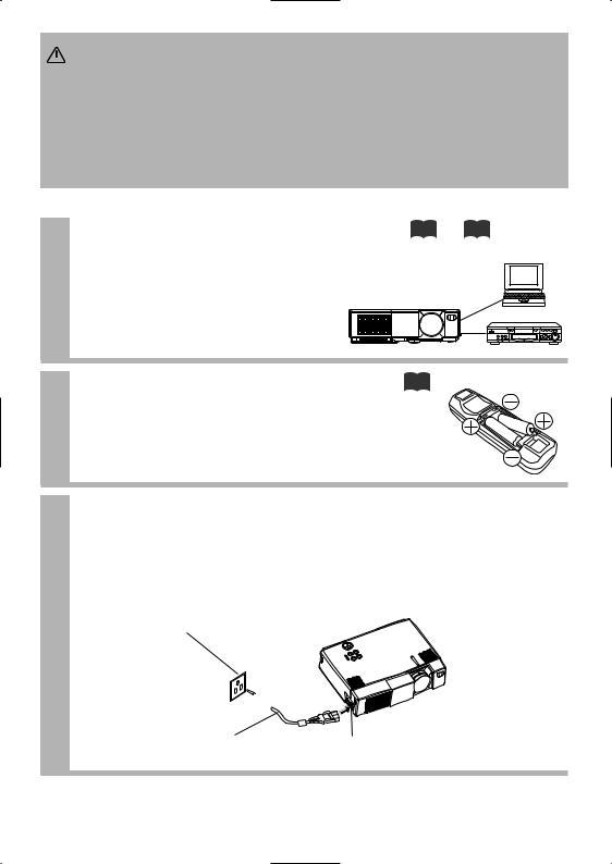
1 |
Connect your devices to the projector |
8 12 |
Connect your computer, VCR and/or other |
|
devices you will be using to the projector.
2 |
Insert the batteries into the remote |
13 |
control |
|
3 Connect the power cord
(1)Connect the connector of the electrical power cord to the AC inlet of the main unit.
(2)Firmly plug the power cord's plug into the outlet
Power outlet
(2) (1)
(1)
Power cord |
AC inlet |
3
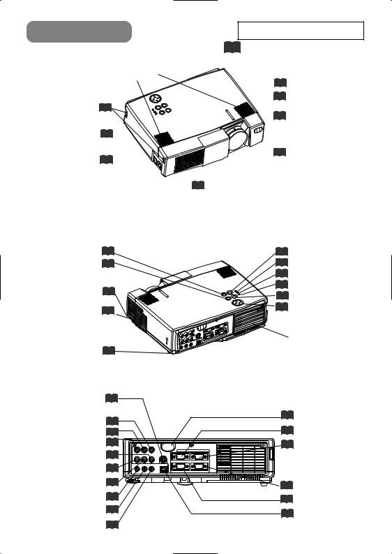
PART NAMES |
THE PROJECTOR |
Handle Hook 34
Power Switch 14
AC Inlet
(to the Power Cord) 3
Ventilation Openings
(Intake)
STANDBY/ON Button 14
KEYSTONE Button 20
Foot Adjuster Button 6
Filter Cover 32
(Air Filter and Intake )
for the Cooling Fan
Rear Foot Adjuster 6
S-VIDEO Port 11
COMPONENT VIDEO
Y Port 11
CB/PB Port 11
CR/PR Port 11
VIDEO IN Port 11
AUDIO IN R Port 11
AUDIO IN L Port 11
AUDIO IN 1 Port 10
AUDIO IN 2 Port 10
AUDIO OUT Port 9
Indicates the corresponding reference page
Speaker
6 Foot Adjuster
1 |
RGB IN |
2 |
AUDIO IN VIDEO IN S-VIDEO IN
15 Zoom Ring
15 Focus Ring
13Remote Control Sensor
14Slide lens door
15 INPUT Button
36 LAMP Indicator
36 TEMP Indicator
14 POWER Indicator
18 RESET Button
23MENU Button
Ventilation Openings (exhaust)
13Remote Control Sensor
10 RGB IN 1 Port
10 RGB IN 2 Port
AUDIO 1 2 AUDIO OUT USB
IN
RGB OUT |
CONTROL |
10 CONTROL Port
12 RGB OUT Port
10 USB Port
TERMINAL PANEL
4

THE REMOTE CONTROL
STANDBY/ON |
STANDBY/ON |
BLANK |
14 |
LASER |
|
|
|
|
button |
|
|
|
VIDEO |
RGB |
VIDEO button 15
Disk Pad 29
AUTO button 19 |
AUTO |
|
|
|
MENU button |
23 |
MENU |
|
KEYSTONE |
|
|
|
||
, , , |
23 |
|
ENTER |
|
|
|
|
||
Cursor buttons |
|
POSITION |
|
RESET |
POSITION button |
18 |
ASPECT |
FREEZE |
ESC |
ASPECT button 22 |
MAGNIFY |
MUTE |
||
|
|
|||
MAGNIFY button 21 |
ON |
OFF |
|
|
|
|
VOLUME |
||
|
|
|
|
|
|
|
|
|
SEARCH |
5LASER button
22 BLANK button
15 RGB button
24MOUSE / RIGHT Button
20 KEYSTONE button
23 ENTER button
18 RESET button
21 FREEZE button
23 ESC button
17 MUTE button
17 VOLUME button
22 SEARCH button
WARNING The laser pointer of the remote control is used in place of a finger or rod. Never look directly into the laser beam outlet or point the laser beam at
other people. The laser beam can cause vision problems.
AVOID EXPOSURE-
LASER RADIATIONS IS
EMITTED FROM THIS
APERTURE
C A U T I O N
LASER RADIATION-
DO NOT STARE INTO BEAM
MAX. OUTPUT: 1mW
WAVE LENGTH: 650nm
CLASS2 LASER PRODUCT
LASER RADIATION
DO NOT STARE INTO BEAM
CLASS2 LASER PRODUCT
MAX. OUTPUT: 1mW
WAVE LENGTH: 650nm
IEC60825-1 : 1993+A1:1997
Complies with 21 CFR 1040. 10 and 1040. 11 except for deviations pursuant to Laser Notice No.50, dated 2001.7.26
SMK CORPORATION
6-5-5 Togoshi Shinagawa-ku, Tokyo, JAPAN 142-8511 MANUFACTURED Novemver 2001
PLACE OF MANUFACTURER: A
NOTE • Keep the remote control away from children and pets.
•Do not give the remote control any physical impact. Take care not to drop.
•Do not place the heavy objects on the remote control.
•Do not wet the remote control or place it on any wet object.
•Do not place the remote control close to the cooling fan of the projector.
•Do not disassemble the remote control.
5
SETTING UP THE PROJECTOR
CAUTION • Install the projector in a suitable environment according to instructions of the “Product Safety Guide” and this "Operator's Guide".
•If you press the elevator buttons without holding the projector, the projector might crash down, overturn, smash your fingers and possibly result in malfunction.
To prevent damaging the projector and injuring yourself, ALWAYS HOLD THE PROJECTOR whenever using the elevator buttons to adjust the elevator feet.
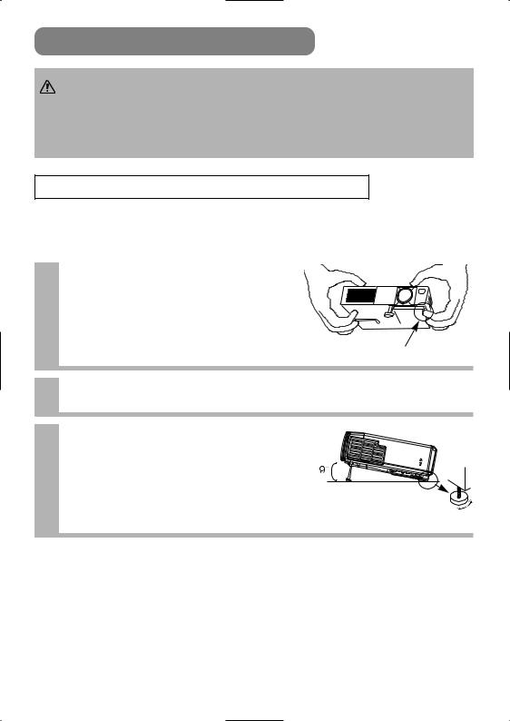
Angle Adjustment
Use the foot adjusters on the bottom of the projector to adjust the projection angle. It is variable within 0˚ to 9˚ approximately.
Lift up the front side of the 1 projector, and pressing the foot adjuster button, adjust the
projection angle.
Press the foot adjuster button
2 Release the button to lock at the desired angle.
Turn the rear foot adjuster to adjust 3 the left-right slope. Do not force the
foot adjuster screws. This could damage the adjusters or cause the lock to fail.
Rear Foot Adjuster
6
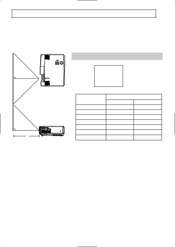
Adjusting the Screen Size and Projection Distance
Refer to the illustrations and tables below to determine the screen size and projection distance.
The values shown in the table are calculated for a full size screen a:Distance from the projector to the screen (±10%)
b:Distance from the lens center to the bottom of the screen (±10%) c:Distance from the lens center to the top of the screen (±10%)
If 4:3 aspect ratio
4
3
Top View
|
|
Screen size |
|
a [inches (m)] |
|
|||
|
|
[inches (m)] |
Min. |
Max. |
||||
|
|
40 |
(1.0) |
47 |
(1.2) |
59 |
(1.5) |
|
|
|
60 |
(1.5) |
71 |
(1.8) |
87 |
(2.2) |
|
|
|
80 |
(2.0) |
94 |
(2.4) |
114 |
(2.9) |
|
|
|
100 |
(2.5) |
118 |
(3.0) |
142 |
(3.6) |
|
|
|
120 |
(3.0) |
142 |
(3.6) |
173 |
(4.4) |
|
a |
|
150 |
(3.8) |
177 |
(4.5) |
217 |
(5.5) |
|
Side View |
200 |
(5.0) |
240 |
(6.1) |
287 (7.3) |
|||
|
||||||||
|
|
|
|
|
|
|
||
7
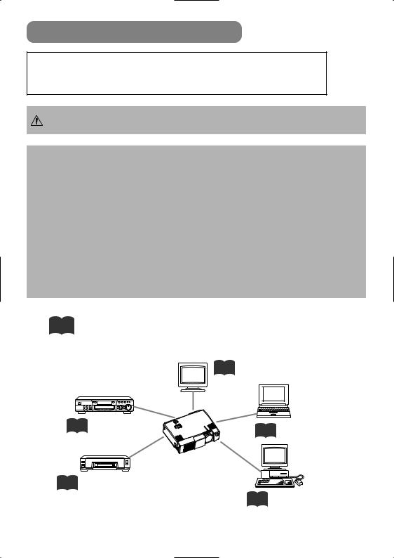
CONNECTING YOUR DEVICES
Devices You Can Connect to the Projector (Refer to this section for planning your device configuration to use for your presentation.)
CAUTION Incorrect connecting could result in fire or electrical shock. Please read the "Product Safety Guide" and this “Operator's Guide”.
ATTENTION Precautions to observe when connecting other devices to the projector :
•Whenever attempting to connect other devices to the projector, please thoroughly read the manual of each device to be connected.
•TURN OFF ALL DEVICES prior to connecting them to the projector. Attempting to connect a live device to the projector may generate extremely loud noises or other abnormalities that may result in malfunction and/or damage to the device and/or projector. Refer to the “TECHNICAL” for the pin assignment of connectors and RS-232C communication data.
•Make sure that you connect devices to the correct port. Incorrect connection may result in malfunction and/or damage to the device and/or projector.
•Some cables may have to be used with core set. Use the accessory cable or a designated-type cable for the connection. For cables that have a core only at one end, connect the core to the projector.
•Secure the screws on the connectors and tighten.
Indicates the corresponding reference page
12 Display monitors
11 DVD players
10 Laptop computers
11 VCRs
10 Desktop computers
8
Ports and Cables
Refer to the table below to find out which projector port and cable to use for connecting a given device. Use this table for determining which cables to prepare.
Function |
Projector Port |
Connection Cables |
|
|
|
|
|
|
|
|
|
RGB input |
RGB IN 1 |
RGB cable |
|
|
|||
|
|||
|
RGB IN 2 |
with D-sub 15-pin shrink jack and |
|
|
|
inch thread screws |
|
RGB output |
RGB OUT |
||
|
|||
|
|
|
|
|
AUDIO IN 1 |
|
|
Audio input |
(interlocked with RGB IN 1) |
Audio cable with stereo mini jack |
|
|
|||
(from the computer) |
AUDIO IN 2 |
||
|
|||
|
|
||
|
(interlocked with RGB IN 2) |
|
|
|
|
|
|
USB mouse control |
USB |
USB cable |
|
|
|
|
|
PS/2 mouse control |
|
PS/2 mouse cable |
|
|
|
|
|
ADB mouse control |
CONTROL |
ADB mouse cable |
|
|
|
||
Serial mouse control |
Serial mouse cable |
||
|
|||
|
|
|
|
RS-232C communication |
|
RS-232C cable |
|
|
|
|
|
S-video input |
S-VIDEO IN |
S-video cable with mini DIN 4-pin jack |
|
|
|
|
|
Video input |
VIDEO IN |
Audio/video cable |
|
|
|
|
|
|
COMPONENT VIDEO Y |
|
|
|
|
|
|
Component video input |
COMPONENT VIDEO CB/PB |
Component video cable |
|
|
|
|
|
|
COMPONENT VIDEO CR/PR |
|
|
|
|
|
|
Audio input |
AUDIO IN L |
Audio/video cable or |
|
|
|||
(from video equipment) |
AUDIO IN R |
Audio cable with RCA jack |
|
|
|
||
|
|
|
|
Audio output |
AUDIO OUT |
Audio cable with stereo mini jack |
|
|
|
|
NOTE About Plug-and-Play Capability
•This projector is compatible with VESA DDC 1/2B. Plug-and-Play can be achieved by connecting this projector to computers that are VESA DDC (display data channel) compatible. Please take advantage of this function by connecting the accessory RGB cable to the RGB IN 1 port (DDC 1/2B compatible). Plug-and-Play may not work properly if any other type of connection is attempted.
•Plug-and-Play is a system composed of the computer, its operating system and peripheral equipment (i.e. display devices).
•Please use the standard drivers as this projector is a Plug-and-Play monitor.
•Plug-and-Play may not function properly with some type of computers. Use the RGB IN 2 port if Plug-and-Play does not function correctly.
9
CONNECTING YOUR DEVICES (continued)
Connecting to a Computer
ATTENTION Whenever attempting to connect a laptop computer to the projector, be sure to activate the laptop's RGB external image output (set the laptop to CRT display or to simultaneous LCD and CRT display). For details on how this is done, please refer to the instruction manual of the corresponding laptop computer.
|
|
|
|
|
1 |
RGB IN |
2 |
|
AUDIO IN |
VIDEO IN |
S-VIDEO IN |
A |
|
|
|
|
|
|
|
|
|
|
|
AUDIO 1 |
2 AUDIO OUT |
USB |
|
|
|
||
IN |
B |
|
|
|
RGB OUT |
|
CONTROL |
|
|
|
|
|
|
||
IN AUDIO |
B |
A |
|
IN RGB |
|||
|
|||
|
AUDIO |
cableRGB |
|
OUT AUDIO |
cable |
Analogue OUT RGB |
USB cable
If connecting to a USB port equipped computer
|
|
|
|
1 |
RGB IN |
2 |
AUDIO IN |
VIDEO IN |
S-VIDEO IN |
|
|
A |
|
|
|
|
|
|
|
|
AUDIO 1 |
2 AUDIO OUT |
USB |
|
|
B |
|
IN |
C |
|
D |
|
|
|
|
|
RGB OUT |
|
CONTROL |
||
D |
C |
|
A |
|
B |
|
|
cableAUDIO |
OUTRGB |
Analogue |
OUTCONTROLIN CONTROL |
cableMOUSE |
|||
OUTUSB IN USB |
OUTAUDIOIN AUDIO |
||||||
|
|
|
IN RGB |
|
|
|
|
|
|
|
cableRGB |
|
|
|
Laptop computer |
Desktop computer |
NOTE
•Some computers may have multiple display screen modes. Use of some of these modes will not be possible with this projector.
•For some RGB input modes, the optional Mac adapter is necessary.
10
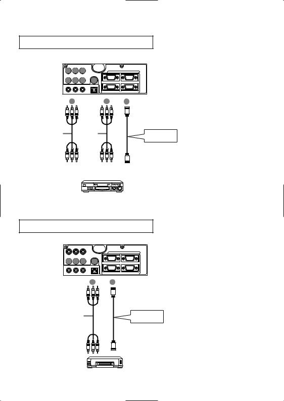
Connecting to a DVD Player
A A A |
1 |
RGB IN |
2 |
||
AUDIO IN |
VIDEO IN |
S-VIDEO IN |
|
|
|
B B B |
C |
|
|
||
AUDIO 1 |
2 AUDIO OUT |
USB |
|
|
|
IN |
|
|
|
|
|
|
|
|
RGB OUT |
CONTROL |
|
A |
|
OUT VIDEO COMPONENT IN VIDEO COMPONENT |
B |
AUDIO/VIDEO |
C |
cable COMPONENT |
|
cable AUDIO/VIDEO |
IN VIDEO-S |
||
|
IN |
S-VIDEO cable |
|||
|
|
||||
|
|
If using a S-video |
|||
|
OUT AUDIO/VIDEO |
connection |
|||
|
OUT VIDEO-S |
||||
If using a component |
If using an audio/video |
video connection |
connection |
DVD player
Connecting to a VCR
|
|
|
|
1 |
RGB IN |
2 |
AUDIO IN VIDEO IN |
S-VIDEO IN |
|
|
|
||
A A A |
B |
|
|
|
|
|
AUDIO 1 |
2 AUDIO OUT |
USB |
|
|
|
|
IN |
|
|
|
|
|
|
|
|
|
|
RGB OUT |
|
CONTROL |
|
|
A |
AUDIO/VIDEO IN AUDIO/VIDEO |
B |
IN VIDEO-S |
|
|
cable AUDIO/VIDEO |
|
|
S-VIDEO cable |
||
|
|
|
|
|||
|
|
|
|
If using a S-video |
||
|
|
|
|
connection |
||
|
|
|
VIDEO-S |
|
||
|
|
|
OUT |
|
OUT |
|
|
|
|
VCR |
|
|
|
11
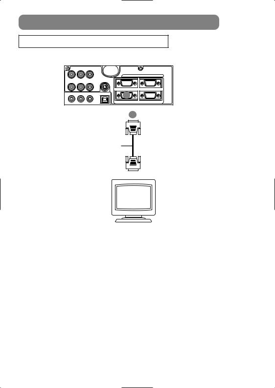
CONNECTING YOUR DEVICES (continued)
Connecting to a Display Monitor
Display monitor
12
 Loading...