


The Network of Networks.
3M™ Crimplok™+ Connector
8700-UPC & APC SM SC 250/900 µm
6700-50 SC 50 µm MM 250/900 µm
6700-50/LOMMF SC 50 µm LOMMF 250/900 µm
6700-62.5 SC 62.5 µm MM 250/900 µm
Instructions
November 2013 |
3 |
78-0013-1746-6-E |

Safety Precautions
Protective Eyewear
CAUTION
To reduce the risk associated with eye injury:
- Safety glasses should be worn when handling chemicals and cleaving the optical fiber.
Chemical Precautions
WARNING
To reduce the risk associated with fire:
- Storage, use and disposal of isopropyl alcohol should be per your company health, safety and environmental instructions. Refer to material safety data sheet for health hazards, safe handling, proper use and control measures.
Bare Fiber Handling
CAUTION
To reduce the risk associated with handling sharp glass fibers:
- Cleaved glass fibers are sharp and can pierce the skin. Use tweezers when handling shards and dispose of them properly per your com- pany health and safety instructions.
Fiber/Cable Handling
NOTICE
To reduce the risk associated with fiber damage:
- Optical fiber can be damaged by excessive tensile, compressive and bending forces. Consult the manufactures’specifications for proper handling instructions.
Laser Safety
CAUTION
To reduce the risk associated with eye damage from exposure to laser light:
- Take the proper precautions when working with optical fiber because invisible laser light may be present. The principal laser hazard when working with fiber optics is injury to the eye. Never look directly into the fiber or connector using the naked eye or a microscope.
2 |
78-0013-1746-6-E |
1.0Overview
1.13M™ Crimplok™+ Connectors 8700-UPC & APC
terminate 250 µm and 900 µm singlemode fibers, and the Crimplok+ 6700 series connectors terminate 250 µm and 900 µm multimode fibers for excellent optical performance.
3M™ Crimplok™+ Connector
N
O
C
A
M I
B L J
P
K
F
H
D
E
G
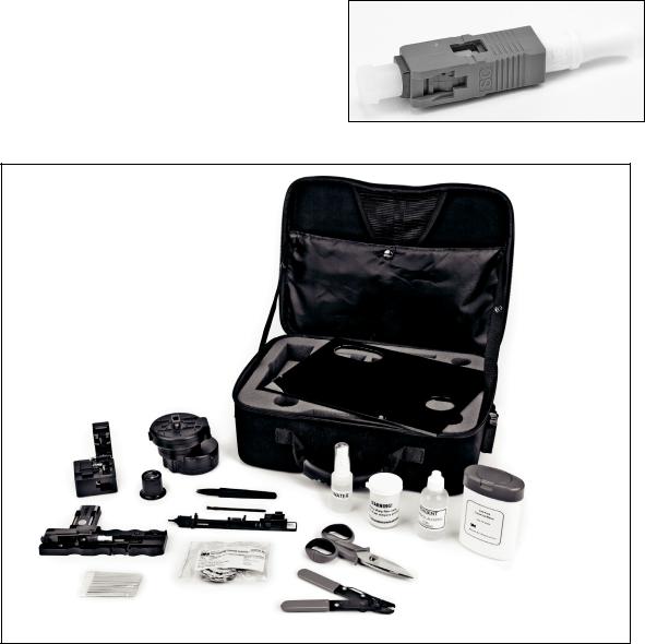
1.2Required tools, available in the 3M Crimplok+ SC/UPC Kit 8765-UPC for the 8700-UPC and 6700 connectors and the 3M Crimplok+ SC/APC Kit 8765-SC/APC for the 8700-APC connector.
A.Cleaver
B.3M Protrusion Setting Tool 8765-PS/UPC for 8700-UPC and 6700, 8765-PS/APC for 8700-
APC
C.3M Nano-finisher 8765-NF/UPC for 8700-UPC and 6700, 8765-NF/APC for 8700-APC
D.3M Green Lapping Film forAPC
3M White Lapping Film for UPC
(included with connectors and also in kit)
E.Cleaning swabs 8765-CS
F.Lint-free wipes 8765-LFW
G.Fiber stripper
H.Fiber snips
I.Tweezers
J.Water spray bottle, empty 8765-WB
K.Alcohol bottle, empty VOL-0560R (optional)
L.Cleaning brush
M.Eye loupe, 10X
N.Case
O.Work surface plate
P.Shard container
Q.Instruction manual (not shown)
Note: The protrusion setting tool and nano-finisher cannot be used with any connectors or processes other than the 3M Crimplok + Connectors.
78-0013-1746-6-E |
3 |
1.3Additional materials needed:
•De-ionized or distilled water for nano-finishing at above-freezing temperatures
•25% to 35% methanol by volume and 75% to
65% de-ionized or distilled water solution by volume for nano-finishing at below-freezing temperatures. DO NOT use ethanol or isopropyl alcohol for nano-finishing.
•99% pure isopropyl alcohol (for cleaning only) or a fiber optic connector cleaning solution approved by your company.
Note: Carefully follow safety, health and environmental information given on product labels or the Material Safety Data Sheets for isopropyl alcohol, fiber optic cleaning fluid, and/or methanol/water solution.
1.4Optional accessory:
3M™ 200X View Scope 6365-VS. DO NOT use when connectors are illuminated by a laser source.
2.0Connector and Protrusion Setting Tool Preparation
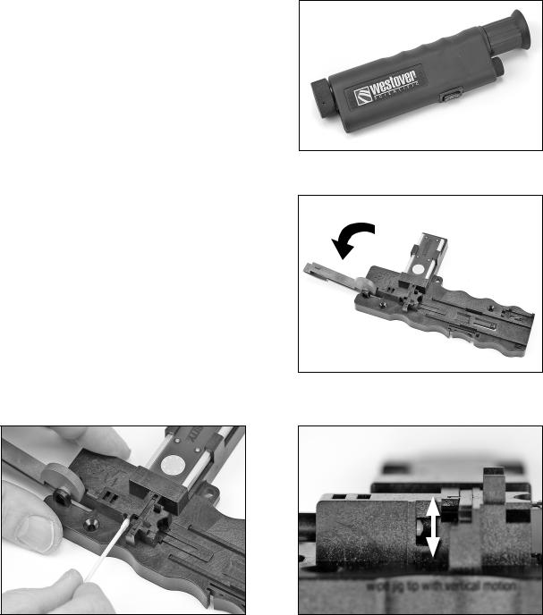
2.1On the 3M™ Protrusion Setting Tool, move the
actuator lever to the unactivated position as shown.
2.2Clean the tip of the protrusion setting jig using a lint-free cleaning swab with a drop of alcohol or cleaning fluid. Reach through the window with the swab and move the swap tip vertically to clean the jig tip.
wipe jig tip with vertical motion
4 |
78-0013-1746-6-E |

2.3Remove the 3M™ Crimplok™+ Connector from the bag and remove the dust cap from the ferrule. Remove the lapping film disc from the bag and set it aside for later.
2.4Insert the connector into the SC port with the actuation cap facing upward. Ensure the connector is fully seated in the port.
Actuation Cap
3.0Fiber Stripping & Cleaving
3.1Open both covers on the cleaver. Move the blade
carriage to the front. Once per day, or whenever the cleaver gets dirty, clean the fiber groove, rubber pads and blade with the brush.
Note: Cleaver can be silver-colored or dark grey-colored.
3.2If working with cable, strip at least 230 mm (9 in.) of cable jacket away to expose just 900 or 250 µm coating. Holding the fiber stripper perpendicular to the fiber, strip enough 900 or 250 µm coating (minimum of 40 mm) to allow the fiber to extend
well beyond the second pad on the cleaver as shown in Section 3.7.
Note: Do not grip the fiber stripper with full strength, because it can damage the tool and weaken the fiber.
78-0013-1746-6-E |
5 |

3.3For 900 µm, determine if the fiber is tight or semitight buffer. If the 900 µm slides easily from the fiber, it is semi-tight buffer fiber. If not, it is tight buffer. Break-out kits for 250 µm are semi-tight. Make note of tight or semi-tight for step 3.11.
3.4For semi-tight 900 µm buffer only, place a second fiber holder 300 mm (12 inches) from the end of the fiber. Latch the buffer clamp closed to ensure a stable cleave length.
3.5Test the stripped fiber for weak points by using your finger to slowly flick the fiber in multiple directions. Watch for the fiber to spring back to the straight position. If the fiber breaks, properly dispose of the broken-off piece and re-strip the fiber.
3.6Thoroughly clean the stripped fiber with a lint-free wipe and alcohol or cleaning fluid. For 250 µm fiber at cold temperatures, use a new lint-free cloth for each stripped fiber. Otherwise the particles on the fiber can snag when inserting the fiber into the connector.
Note: Carefully follow safety, health and environmental information given on the product label or the Material Safety Data Sheet for the isopropyl alcohol or cleaning fluid.
3.7Lay the 900 µm fiber into the larger of the 2 tracks on the cleaver. Cleave it to 24 mm, by aligning the coating edge with the left-most line on the fiber track. Lay the 250 µm fiber into the smaller track on the cleaver. Cleave it to 19 mm using the middle line. (If you are using another cleaver model or one from the 3M™ No Polish Connector Kit, then mark it at
24 mm and 19 mm.)
40 mm
250 µm coating edge
900 µm coating edge
6 |
78-0013-1746-6-E |
 Loading...