


3M 25127, 28345, 28332, 28330, 20238 User Manual
...3
Die Grinder INSTRUCTIONS MANUAL
8,000 RPM 1/4 in (6 mm) Collet 1 HP, 12,000 RPM 1/4 in (6 mm) Collet 1 HP, 18,000 RPM 1/4 in (6 mm) Collet 1 HP, 20,000 RPM 1/4 in (6 mm) Collet 1 HP, 4,000 RPM 1/4 in (6 mm) Collet 0.5 HP, 18,000, RPM 1/4 in (6 mm) Collet
0.5 HP, Extended 18,000 RPM 1/4 in (6 mm) Collet 0.5 HP
Important Safety Information
Please read, understand and follow all safety information contained in these instructions prior to the use of this tool.
Retain these instructions for future reference.
Intended Use
This pneumatic tool is intended for use in industrial locations, and used only by skilled, trained professionals in accordance with the instructions in this manual. This pneumatic tool is designed to be used with a disc pad and abrasive disc or other shaft mounted abrasive product for sanding metals, wood, stone, plastics and other materials. It should only be used for such sanding applications and within its marked capacity and ratings. Only accessories specifically recommended by 3M should be used with this tool. Use in any other manner or with other accessories could lead to unsafe operating conditions.
Do not operate tool in water or in an excessively wet application.
Do not use abrasive products that have a Max RPM less than the RPM rating marked on the tool.
Explanation of Signal Word Consequences
WARNING: Indicates a potentially hazardous situation which, if not avoided, may result in death or serious injury and/or property damage.  CAUTION: Indicates a potentially hazardous situation which, if not avoided, may result in minor or moderate injury and/or property damage.
Read the Material Safety
Data Sheets (MSDS) before using any materials.
MSDS
Contact the suppliers of the workpiece materials and abrasive materials for copies of the MSDS if one is not readily available.
 WARNING!
Exposure to DUST generated from workpiece and/or abrasive materials can result in lung damage and/or other physical injury.
Use dust capture or local exhaust as stated in the MSDS. Wear governmentapproved respiratory protection and eye and skin protection.
Failure to follow this warning can result in serious lung damage and/or physical injury.
 WARNING
To reduce the risks associated with impact from abrasive product or tool breakup, sharp edges, hazardous pressure, rupture, vibration and noise:
•Read, understand and follow the safety information contained in these instructions prior to the use of this tool. Retain these instructions for future reference.
•Only personnel who are properly trained should be allowed to service this tool.
•Practice safety requirements. Work alert, have proper attire, and do not operate tool under the influence of alcohol or drugs.
•Operators and other personnel must always wear protection for eyes, ears, and respiratory protection when in the work area or while operating this product. Follow your employer’s safety policy for PPE’s and/or ANSI Z87.1 or local/national standards for eyewear and other personal protective equipment requirements.
•Wear protective apparel, taking into consideration the type of work being done.
•Never exceed marked maximum input pressure (90psi / .62Mpa / 6.2Bars).
•Proper eye protection must be worn at all times.
•Tool shall not be operated in the presence of bystanders.
•If you notice any abnormal noise or vibration when operating the product, immediately discontinue its use and inspect for worn or damaged components. Correct or replace the suspect component. If abnormal noise or vibration still exists, return the tool to 3M for repair or replacement. Refer to warranty instructions.
Original Instructions
 WARNING
•Never operate this tool without all safety features in place and in proper working order.
•Never over-ride or disable the safety features of the start-stop control such that it is in the on position.
•Make sure the tool is disconnected from its air source before servicing, inspecting, maintaining, cleaning, and before changing abrasive product.
•Prior to use, inspect abrasive product and accessories for possible damage. If damaged, replace with new abrasive product and accessories available from 3M.
•Only use accessories supplied or recommended by 3M.
•Use only with mounting hardware recommended by 3M; check with 3M for mounting hardware requirements.
•Always ensure that shaft diameters match internal diameters of the collet inserts.
•Maximum operating speed of abrasive products or accessories must be reduced whenever the exposed length of shaft (overhang) is longer than corresponding 3M approved products.
•Always ensure that a minimum of 10mm shaft gripping length is observed.
•Never install and use router bits or cutting-off wheels in a die grinder tool (which is unguarded).
•Use only with abrasive products not requiring guards according to local, state and federal regulations.
•Never allow this tool to be used by children or other untrained people.
•Do not leave an unattended tool connected to air source.
To reduce the risk of all hazards associated with vibration:
•If any physical hand/wrist discomfort is experienced, work should be stopped promptly to seek medical attention. Hand, wrist and arm injury may result from repetitive work, motion and overexposure to vibration.
To reduce the risks associated with loud noise:
• Always wear protection for eyes, ears, and respiratory protection while operating this product. Follow your employer’s safety policy for PPE’s and/or ANSI Z87.1 or local/national standards for eyewear and other personal protective equipment requirements.
To reduce the risk associated with fire or explosion:
•Do not operate the tool in explosive atmospheres, such as in the presence of flammable liquids, gases, or dust. The abrasives are able to create sparks when working material, resulting in the ignition of the flammable dust or fumes.
•Refer to MSDS of material being worked as to potential for creating fire or explosion hazard.
To reduce the risk associated with hazardous dust ingestion or eye/skin exposure:
• Use appropriate respiratory and skin protection, or local exhaust as stated in the MSDS of the material being worked on.
To reduce the risk associated with hazardous voltage:
• Do not allow this tool to come into contact with electrical power sources as the tool is not insulated against electrical shock.
 CAUTION
To reduce the risk associated with skin abrasion, burns, cuts, or entrapment:
•Keep hands, hair, and clothing away from the rotating part of the tool.
•Wear suitable protective gloves while operating tool.
•Do not touch the rotating parts during operation for any reason.
•Do not force tool or use excessive force when using tool.
To reduce the risk associated with whipping or hazardous pressure-rupture:
•Ensure supply hose is oil resistant and is properly rated for required working pressure.
•Do not use tools with loose or damaged air hoses or fittings.
•Be aware that incorrectly installed hoses and fittings might unexpectedly come loose at any time and create a whipping/impact hazard.
To reduce the risk associated with fly off of abrasive product or parts:
•Use care in attaching abrasive product and mounting hardware; following the instructions to ensure that they are securely attached to the tool before use or free-spinning.
•Never point this product in the direction of yourself or another person, or start tool unintentionally.
•Never over-tighten accessory fasteners.
1 |
2 |
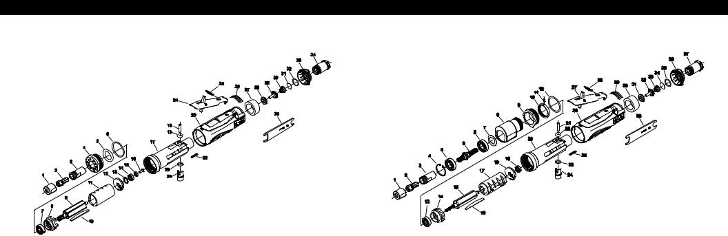
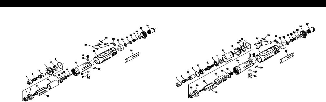
Parts Page
PARTS LIST FOR PN 20237 & 25126, 20,000 RPM and 20238 & 25127, 18,000 RPM DIE GRINDERS
Fig. |
3M PN |
Description |
Fig. |
3M PN |
Description |
1 |
06572 |
Collet Nut |
16 |
06568 |
Screw #8-32 x 3/8 in |
2 |
06545 |
Collet (3/8 in) |
|
|
But Hd Cap |
2 |
06546 |
Collet (8 mm) |
17 |
06638 |
Housing |
2 |
06573 |
Collet (1/8 in) |
18 |
06558 |
Torr Pin, 3/16 in x 7/8 in |
2 |
06574 |
Collet (3/16 in) |
19 |
06543 |
O-Ring |
2 |
06575 |
Collet (1/4 in) |
20 |
06511 |
O-Ring |
2 |
06576 |
Collet (3 mm) |
21 |
06556 |
Regulator |
2 |
06577 |
Collet (6 mm) |
22 |
06501 |
Screw, 6-32 x 3/4 in |
3 |
06571 |
Collet Body |
|
|
Set Soc Hex |
4 |
06565 |
Retainer |
23 |
06598 |
Housing Cover |
5 |
06579 |
O-Ring 7/8 in x 1/4 in x |
24 |
06642 |
Lever |
|
|
3/16 in |
25 |
06559 |
Groove Pin, 1/8 in x 7/8 in |
6 |
06609 |
O-Ring |
|
|
Type E |
7 |
06510 |
Ball Bearing |
26 |
06566 |
Warning Label |
|
|
3/8 in x 7/8 in x 9/32 in |
27 |
06557 |
Muffler |
8 |
06639 |
Front End Plate |
28 |
06552 |
Throttle Valve Seat |
9 |
06561 |
Rotor |
29 |
06553 |
Throttle Valve |
10 |
06643 |
Vane, Set of 5 |
30 |
06554 |
Taper Spring |
11 |
06601 |
Cylinder (20,000 RPM) |
31 |
06555 |
Screen |
11 |
06564 |
Cylinder (18,000 RPM) |
32 |
06608 |
O-Ring, 1/16 in x 5/8 in |
12 |
06560 |
Rear End Plate |
|
|
x 3/4 in |
13 |
06527 |
Wave Washer |
33 |
06604 |
Rotatable Exhaust |
|
|
.440 in x .618 in x .008 in |
|
|
Deflector |
14 |
06508 |
Ball Bearing |
34 |
06605 |
Inlet Bushing |
15 |
06567 |
Washer |
35 |
06569 |
9/16 in x 3/4 in Wrench (2) |
|
|
.251 in x .468 in x .063 in |
|
|
|
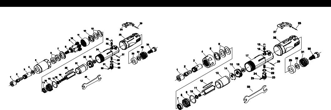
Parts Page
PARTS LIST FOR PN 20239 & 25128, 12,000 RPM and 20240 & 25129, 8,000 RPM DIE GRINDERS
Fig. |
3M PN |
Description |
Fig. |
3M PN |
Description |
1 |
06572 |
Collet Nut |
16 |
06643 |
Vane, Set of 5 |
2 |
06545 |
Collet (3/8 in) |
17 |
06602 |
Cylinder (12,000 RPM) |
2 |
06546 |
Collet (8 mm) |
17 |
06600 |
Cylinder (8,000 RPM) |
2 |
06573 |
Collet (1/8 in) |
18 |
06560 |
Rear End Plate |
2 |
06574 |
Collet (3/16 in) |
19 |
06508 |
Ball Bearing |
2 |
06575 |
Collet (1/4 in) |
20 |
06638 |
Housing |
2 |
06576 |
Collet (3 mm) |
21 |
06558 |
Torr Pin, 3/16 in x 7/8 in |
2 |
06577 |
Collet (6 mm) |
22 |
06543 |
O-Ring |
3 |
06571 |
Collet Body |
23 |
06511 |
O-Ring |
4 |
06518 |
Retaining Ring |
24 |
06556 |
Regulator |
5 |
06507 |
Ball Bearing |
25 |
06501 |
Screw, 6-32 x 3/4 in Set |
6 |
06587 |
12,000 RPM Grinder Output |
|
|
Soc Hex |
|
|
Shaft |
26 |
06598 |
Housing Cover |
6 |
06592 |
8,000 RPM Grinder Output |
27 |
06642 |
Lever |
|
|
Shaft |
28 |
06559 |
Groove Pin, 1/8 in x 7/8 in |
7 |
06521 |
Wave Washer |
|
|
Type E |
8 |
06588 |
12,000 RPM GrinderGear Box |
29 |
06566 |
Warning Label |
8 |
06593 |
8,000 RPM Grinder Gear Box |
30 |
06557 |
Muffler |
9 |
06653 |
Angle Head Clamp Nut |
31 |
06552 |
Throttle Valve Seat |
10 |
06655 |
Lock Ring |
32 |
06553 |
Throttle Valve |
11 |
06520 |
Pin, 1/8 in x 1/4 in |
33 |
06554 |
Taper Spring |
12 |
06609 |
O-Ring |
34 |
06555 |
Screen |
13 |
06506 |
Ball Bearing 3/8 in x 7/8 in |
35 |
06608 |
O-Ring, 1/16 in x 5/8 in |
|
|
x 9/32 in |
|
|
x 3/4 in |
14 |
06603 |
Front End Plate |
36 |
06604 |
Rotatable Exhaust Deflector |
15 |
06640 |
Rotor |
37 |
06605 |
Inlet Bushing |
|
|
|
38 |
06569 |
9/16 in x 3/4 in Wrench (2) |
3 |
4 |
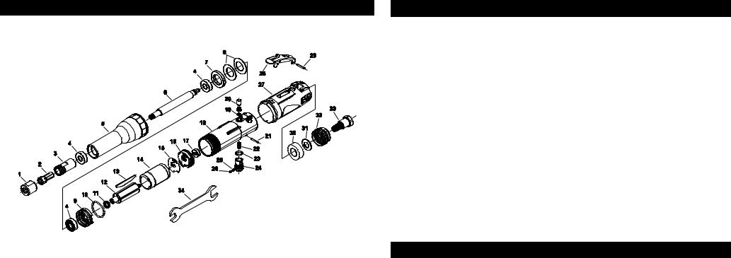
Parts Page
PARTS LIST FOR PN 28332 & 28347, 4,000 RPM DIE GRINDERS
Fig. |
3M PN |
Description |
Fig. |
3M PN |
Description |
1 |
06572 |
Collet Nut |
19 |
30424 |
Rotor |
2 |
06575 |
Collet (1/4 in) |
20 |
06647 |
Vane, Set of 4 |
2 |
06573 |
Collet (1/8 in) |
21 |
06631 |
Cylinder Liner |
2 |
06574 |
Collet (3/16 in) |
22 |
06630 |
Rear End Plate |
2 |
06545 |
Collet (3/8 in) |
23 |
06612 |
Ball Bearing |
2 |
06576 |
Collet (3mm) |
24 |
06625 |
Housing |
2 |
06577 |
Collet (6mm) |
25 |
30400 |
O-Ring |
2 |
06546 |
Collet (8mm) |
26 |
06626 |
Trigger Valve Stem |
3 |
06571 |
Collet Body |
27 |
06616 |
Pin |
4 |
30397 |
Spring Steel Washer |
28 |
06614 |
Compression Spring |
5 |
30374 |
Clamp Nut |
29 |
06620 |
O-Ring |
6 |
30389 |
Ball Bearing (2) |
30 |
06627 |
Air Regulator |
7 |
30396 |
Flat Washer |
31 |
06613 |
Compression Spring |
8 |
30372 |
Gear Carrier |
32 |
06622 |
Steel Ball |
9 |
30393 |
Pin(3) |
33 |
06599 |
Housing Cover, .5 HP |
10 |
30408 |
Planet Gear (3) |
34 |
06635 |
Paddle Assembly |
11 |
30425 |
Ring Gear |
35 |
06617 |
Roll Pin |
12 |
30423 |
Pilot (.75 ID) |
36 |
06632 |
Muffler Material |
13 |
30392 |
Spring Washer (2) |
37 |
06615 |
Disc Spring |
14 |
06611 |
Ball Bearing |
38 |
06628 |
Exhaust Deflector |
15 |
06629 |
Front End Plate |
39 |
06618 |
Inlet Bushing |
16 |
06621 |
O-Ring |
40 |
06569 |
9/16 in x 3/4 in Wrench (2) |
17 |
30418 |
Front End Plate Spacer |
|
|
|
18 |
30402 |
O-Ring |
|
|
|
Parts Page
PARTS LIST FOR PN 28330 & 28345, 18,000 RPM DIE GRINDERS
Fig. |
3M PN |
Description |
Fig. |
3M PN |
Description |
1 |
06572 |
Collet Nut |
16 |
06612 |
Ball Bearing |
2 |
06575 |
Collet (1/4 in) |
17 |
06625 |
Housing |
2 |
06573 |
Collet (1/8 in) |
18 |
30400 |
O-Ring |
2 |
06574 |
Collet (3/16 in) |
19 |
06626 |
Trigger Valve Stem |
2 |
06545 |
Collet (3/8 in) |
20 |
06616 |
Pin |
2 |
06576 |
Collet (3mm) |
21 |
06614 |
Compression Spring |
2 |
06577 |
Collet (6mm) |
22 |
06620 |
O-Ring |
2 |
06546 |
Collet (8mm) |
23 |
06627 |
Air Regulator |
3 |
30371 |
Collet Body |
24 |
06613 |
Compression Spring |
4 |
06636 |
Clamp Nut |
25 |
06622 |
Steel Ball |
5 |
30419 |
Disk Spring Spacer |
26 |
06599 |
Housing Cover, .5 HP |
6 |
30392 |
Spring Washer (2) |
27 |
06635 |
Paddle Assembly |
7 |
06611 |
Ball Bearing |
28 |
06617 |
Roll Pin |
8 |
06629 |
Front End Plate |
29 |
06632 |
Muffler Material |
9 |
06621 |
O-Ring |
30 |
06615 |
Disc Spring |
10 |
30418 |
Front End Plate Spacer |
31 |
06628 |
Exhaust Deflector |
11 |
06634 |
Rotor |
32 |
06618 |
Inlet Bushing |
12 |
06647 |
Vane, Set of 4 |
33 |
06569 |
9/16 in x 3/4 in Wrench (2) |
13 |
06631 |
Cylinder Liner |
|
|
|
14 |
30373 |
Motor Restricting Washer |
|
|
|
15 |
06630 |
Rear End Plate |
|
|
|
5 |
6 |
Parts Page
PARTS LIST FOR PN 28331 & 28346, Extended 18,000 RPM DIE GRINDERS
Fig. |
3M PN |
Description |
Fig. |
3M PN |
Description |
1 |
06572 |
Collet Nut |
16 |
06630 |
Rear End Plate |
2 |
06575 |
Collet (1/4 in) |
17 |
06612 |
Ball Bearing |
2 |
06573 |
Collet (1/8 in) |
18 |
06625 |
Housing |
2 |
06574 |
Collet (3/16 in) |
19 |
30400 |
O-Ring |
2 |
06545 |
Collet (3/8 in) |
20 |
06626 |
Trigger Valve Stem |
2 |
06576 |
Collet (3mm) |
21 |
06616 |
Pin |
2 |
06577 |
Collet (6mm) |
22 |
06614 |
Compression Spring |
2 |
06546 |
Collet (8mm) |
23 |
06620 |
O-Ring |
3 |
30371 |
Collet Body |
24 |
06627 |
Air Regulator |
4 |
06611 |
Ball Bearing (3) |
25 |
06613 |
Compression Spring |
5 |
30420 |
Clamp Nut |
26 |
06622 |
Steel Ball |
6 |
30421 |
Extension Shaft |
27 |
06599 |
Housing Cover, .5 HP |
7 |
30423 |
Pilot (.75 ID) |
28 |
06635 |
Paddle Assembly |
8 |
30392 |
Spring Washer (2) |
29 |
06617 |
Roll Pin |
9 |
06629 |
Front End Plate |
30 |
06632 |
Muffler Material |
10 |
06621 |
O-Ring |
31 |
06615 |
Disc Spring |
11 |
30418 |
Front End Plate Spacer |
32 |
06628 |
Exhaust Deflector |
12 |
30422 |
Rotor |
33 |
06618 |
Inlet Bushing |
13 |
06647 |
Vane, Set of 4 |
34 |
06569 |
9/16 in x 3/4 in Wrench (2) |
14 |
06631 |
Cylinder Liner |
|
|
|
15 |
30373 |
Motor Restricting Washer |
|
|
|
Product Configuration / Specifications
|
|
|
|
|
|
|
|
Product Net |
|
Height |
|
Length mm |
|
*Noise Lever |
|
**Vibration |
|
**Uncertainty |
|||||||
|
Model Number |
|
Collet |
Speed RPM |
|
Wt kg |
|
|
|
dBA Pressure |
|
Level m/s2 |
|
||||||||||||
|
|
|
|
mm (in) |
|
(in) |
|
|
|
K m/s2 |
|||||||||||||||
|
|
|
|
|
|
|
|
(lb) |
|
|
|
(Power) |
|
(ft/s2) |
|
||||||||||
|
|
|
|
|
|
|
|
|
|
|
|
|
|
|
|
|
|
|
|||||||
|
20237 |
|
|
1/4 in |
|
20,000 |
|
0.77 (1.69) |
|
|
76.2 (3) |
|
|
196 (7.5) |
|
|
83.5 (95.1) |
|
|
< 2.5 |
(< 8.2) |
|
|
NA |
|
25126 |
|
|
6 mm |
0.77 (1.69) |
|
76.2 (3) |
|
196 (7.5) |
|
83.5 (95.1) |
|
< 2.5 |
(< 8.2) |
|
|
NA |
|||||||||
|
|
|
|
|
|
|
|
|
|||||||||||||||||
|
|
|
|
|
|
|
|
|
|
|
|
|
|
|
|
|
|
|
|
|
|
|
|
|
|
|
20238 |
|
|
1/4 in |
|
18,000 |
|
0.77 (1.69) |
|
|
76.2 (3) |
|
|
196 (7.5) |
|
|
83.5 (95.1) |
|
|
< 2.5 |
(< 8.2) |
|
|
NA |
|
25127 |
|
|
6 mm |
0.77 (1.69) |
|
76.2 (3) |
|
196 (7.5) |
|
83.5 (95.1) |
|
< 2.5 |
(< 8.2) |
|
|
NA |
|||||||||
|
|
|
|
|
|
|
|
|
|||||||||||||||||
|
|
|
|
|
|
|
|
|
|
|
|
|
|
|
|
|
|
|
|
|
|
|
|
|
|
|
20239 |
|
|
1/4 in |
|
12,000 |
|
0.93 (2.06) |
|
|
81.2 (3.2) |
|
|
254 (10) |
|
|
83.5 (95.1) |
|
|
3.62 |
(11.9) |
|
|
1.81 |
|
25128 |
|
|
6 mm |
0.93 (2.06) |
|
81.2 (3.2) |
|
254 (10) |
|
83.5 (95.1) |
|
3.62 |
(11.9) |
|
1.81 |
|
|||||||||
|
|
|
|
|
|
|
|
|
|||||||||||||||||
|
|
|
|
|
|
|
|
|
|
|
|
|
|
|
|
|
|
|
|
|
|
|
|
|
|
|
20240 |
|
|
1/4 in |
|
8,000 |
|
0.93 (2.06) |
|
|
81.2 (3.2) |
|
|
254 (10) |
|
|
83.5 (95.1) |
|
|
3.62 |
(11.9) |
|
|
1.81 |
|
25129 |
|
|
6 mm |
0.93 (2.06) |
|
76.2 (3.2) |
|
254 (10) |
|
83.5 (95.1) |
|
3.62 |
(11.9) |
|
1.81 |
|
|||||||||
|
|
|
|
|
|
|
|
|
|||||||||||||||||
|
|
|
|
|
|
|
|
|
|
|
|
|
|
|
|
|
|
|
|
|
|
|
|
|
|
|
28332 |
|
|
1/4 in |
|
4,000 |
|
0.717 (1.58) |
|
|
69.9 (2.75) |
|
|
200 (8.875) |
|
|
87.0 (98.6) |
|
|
5.52 |
|
|
0.732 |
|
|
28347 |
|
|
6 mm |
0.717 (1.58) |
|
69.9 (2.75) |
|
200 (8.875) |
|
87.0 (98.6) |
|
5.52 |
|
0.732 |
|
||||||||||
|
|
|
|
|
|
|
|
|
|||||||||||||||||
|
|
|
|
|
|
|
|
|
|
|
|
|
|
|
|
|
|
|
|
|
|
|
|
|
|
|
28330 |
|
|
1/4 in |
|
18,000 |
|
0.512 (1.13) |
|
|
69.9 (2.75) |
|
|
174.6 (6.875) |
|
|
87.0 (98.6) |
|
|
1.91 |
|
|
NA |
|
|
28345 |
|
|
6 mm |
0.512 (1.13) |
|
69.9 (2.75) |
|
174.6 (6.875) |
|
83.5 (95.1) |
|
1.91 |
|
|
NA |
||||||||||
|
|
|
|
|
|
|
|
|
|||||||||||||||||
|
|
|
|
|
|
|
|
|
|
|
|
|
|
|
|
|
|
|
|
|
|
|
|
|
|
|
28331 |
|
|
1/4 in |
|
18,000 |
|
0.697 (1.54) |
|
|
69.9 (2.75) |
|
269.9 (10.625) |
|
|
87.0 (98.6) |
|
|
2.53 |
|
|
0.295 |
|
||
28346 |
|
|
6 mm |
0.697 (1.54) |
|
69.9 (2.75) |
|
269.9 (10.625) |
|
87.0 (98.6) |
|
2.53 |
|
0.295 |
|
||||||||||
|
|
|
|
|
|
|
|
|
|||||||||||||||||
|
|
|
|
|
|
|
|
|
|
|
|
|
|
|
|
|
|
|
|
|
|
|
|
|
|
* Declared noise levels; measurements carried out in accordance with standard EN ISO 15744:2002.
** Declared vibration levels in accordance with EN12096; measurements carried out in accordance with standard EN ISO 8662-13:1997.
IMPORTANT NOTE: The noise and vibration values stated in the table are from laboratory testing in conformity with stated codes and standards and are not sufficient risk evaluation for all exposure scenarios. The actual exposure values and amount of risk or harm experienced to an individual is unique to each situation and depends upon the surrounding environment, the way in which the individual works, the particular material being worked, work station design, as well as upon the exposure time and the physical condition of the user. 3M cannot be held responsible for the consequences of using declared values instead of actual exposure values for any individual risk assessment.
Operating / Maintenance Instructions
PRIOR TO THE OPERATION
The tool is intended to be operated as a hand held tool. It is always recommended that while using the tool, operators stand on a solid floor, in a secure position with a firm grip and footing. Be aware that the sander can develop a torque reaction. See the section inSAFETY PRECAUTIONS in.
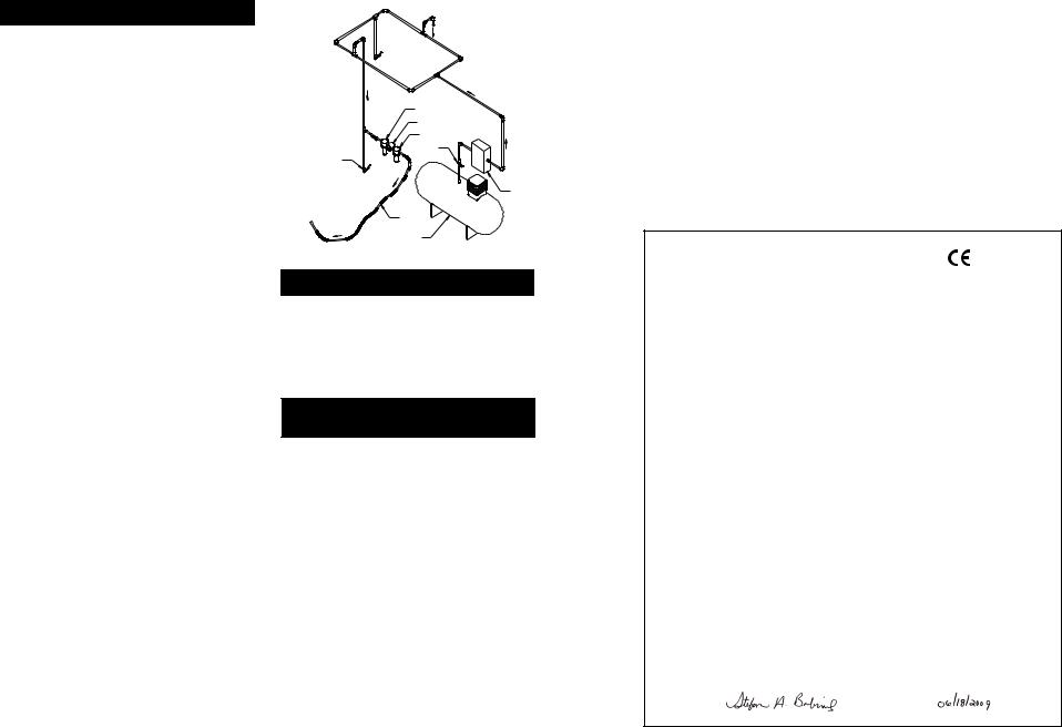
Use a clean lubricated air supply that will give a measured air pressure at the tool of 6.2 bar (90 psig) when the tool is running with the lever fully depressed. It is recommended to use an approved 10 mm (3/8 in) x 8 m (25 ft) maximum length airline. Connect the tool to the air supply as shown in Figure 1. Do not connect the tool to the airline system without an easily accessible air shut off valve. It is strongly recommended that an air filter, regulator and lubricator (FRL) be used as shown in Figure 1 as this will supply clean, lubricated air at the correct pressure to the tool. In any case appropriate air pressure regulators shall be used at all times while operating this tool where the supply pressure exceeds the marked maximum of the tool. Details of such equipment can be obtained for your tool distributor. If such equipment is not used, the tool should be manually lubricated. To manually lubricate the tool, disconnect the airline and put 2 to 3 drops of suitable pneumatic motor lubricating oil such as 3M™ Air Tool Lubricant PN 20451, Fuji Kosan FK-20 or Mobil ALMO 525 into the hose end (inlet) of the tool. Reconnect tool to the air supply and run tool slowly for a few seconds to allow air to circulate the oil. If the tool is used frequently, lubricate it on a daily basis or
lubricate it if the tool starts to slow or lose power. It is recommended that the air pressure at the tool be 6.2 bar (90 psig) while the tool is running so the maximum RPM is not exceeded. The tool can be run at lower pressures but should never be run higher than 6.2 bar (90 psig). If run at lower pressure the performance of the tool is reduced.
|
Recommended Airline |
Recommended Maximum Hose Length |
Air Pressure |
|
||
|
Size - Minimum |
|
|
Maximum Working Pressure |
6.2 bar |
90 psig |
10 mm |
3/8 in |
8 meters |
25 feet |
Recommended Minimum |
N/A |
N/A |
|
|
|
||||
|
|
|
|
|
|
|
7 |
8 |
Safety Precautions
1.Read all instructions before using this tool. All operators must be fully trained in its use and aware of these safety rules.
2.The tool RPM should be checked on a regular basis to ensure proper operating speed.
3.Make sure the tool is disconnected from the air supply. Select a suitable abrasive and secure it to the disc pad or spindle. Be careful to center the abrasive on the disc pad.
4.Always wear required safety equipment when using this tool.
5.Always remove the air supply to the sander before fitting, adjusting or removing the abrasive or disc pad.
6.Always adopt a firm footing and grip and be aware of torque reaction developed by the sander.
7.Use only 3M approved spare parts.
8.Always ensure the material being worked is firmly fixed to avoid movement.
9.Check hose and fittings regularly for wear. Do not carry the tool by its hose; always be careful to prevent the tool from being started when carrying the tool with the air supply connected.
10.Dust can be highly combustible.
11.If tool is serviced or rebuilt check to ensure that the maximum tool RPM is not exceeded and that there is no excessive tool vibration.
12.Do not exceed maximum recommended air pressure. Use safety equipment as recommended.
13.Prior to installing any shaft mounted abrasive or sanding or grinding accessory, always check that its marked maximum operating speed is equal or higher than the rated speed of this tool.
14.The tool is not electrically insulated. Do not use where there is a possibility of contact with live electricity, gas pipes, and/or water pipes.
15.This tool is not protected against hazards inherent in cutting operations, and no such cutting products should ever be attached.
16.Take care to avoid entanglement with the moving parts of the tool with clothing, ties, hair, cleaning rags or loose hanging objects. If entangled, stop air supply immediately to avoid contact with moving tool parts.
17.Keep hands clear of the spinning pad or spindle during use.
18.If the tool appears to malfunction, remove from use immediately and arrange for service and repair.
19.Do not allow the tool to free spin without taking precautions to protect any persons or objects from the loss of the abrasive or pad ruptures.
20.Immediately release the start handle in the event of any disruption of pressure; do not attempt to re-start until the disruption has been corrected.
21.When tool is not in use, store in a clean, dry environment free of debris.
22.Recycle or dispose of tool according to Local, State, and Federal regulations.
|
Closed Loop Pipe System |
Drain Leg |
Sloped in the direction of air flow |
|
|
Ball Valve |
|
To Tool Station |
|
|
Filter |
Ball |
Regulator |
Valve |
Lubricator |
|
|
Ball Valve |
Air Flow |
|
|
|
||
|
Drain Valve |
|
|
|
|
Air Dryer |
|
|
Air Hose |
|
|
To Coupler |
Air Compressor |
|
|
at or near Tool |
|
||
and Tank |
Figure 1 |
||
|
|||
|
|
3M™ Die Grinder
3M™ Die Grinder accessories are designed for use on 3M Die Grinders. Constructed from premium, industrial-quality materials, their durability and precise construction are the ideal complement to the performance of the 3M Die Grinder. See Product Configuration/Specifications table for the correct replacement pad for a particular model.
See 3M ASD Accessory catalog 61-5002-8098-9 and 61-5002-8097-1 for additional Accessories.
Removing and remounting shanks and shaft mounted abrasive products into collet chuck
1.Disconnect air line from tool.
2.Remove currently mounted shaft accessory, shank or abrasive product from collet chuck* by using the two wrenches supplied with the tool. Use the wrench to secure the collet body while turning the collet nut counter clockwise.
3.After the existing product has been removed from the collet, inspect the collet insert to ensure that is free of debris and undamaged.
4.Fully insert the new shaft mounted accessory, shank or abrasive product into the collet.
5.Secure the collet body with the wrench and tighten the collet nut securely. Always use the correct sized collet with the matching shank (use 1/4 in collet insert with 1/4 in shafts or 6 mm collet insert with 6 mm shafts). An inadequately inserted shank could bend or break causing damage to the tool and work piece and possible injury to the operator or bystanders.
Note: During the above steps, ensure that all hardware and abrasive products are mounted concentrically on the supporting accessory.
*In the drawings on the Parts Pages, Figures 1, 2 and 3 comprise the Collet Chuck.
Product Use: All statements, technical information and recommendations contained in this document are based up on tests or experience that 3M believes are reliable. However, many factors beyond 3M’s control can affect the use and performance of a 3M product in a particular application, including the conditions under which the 3M product is used and the time and environmental conditions in which the product is expected to perform. Since these factors are uniquely within the user’s knowledge and control, it is essential that the user evaluate the 3M product to determine whether it is fit for a particular purpose and suitable for the user’s method of application. Warranty and Limited Remedy: 3M warrants this tool against defects
in workmanship and materials under normal operating conditions for one
(1) year from the date of purchase. 3M MAKES NO OTHER WARRANTIES, EXPRESS OR IMPLIED, INCLUDING, BUT NOT LIMITED TO, ANY IMPLIED WARRANTY OF MERCHANTABILITY OR FITNESS FOR A PARTICULAR PURPOSE OR ANY IMPLIED WARRANTY ARISING OUT OF A COURSE OF DEALING, CUSTOM OR USAGE OF TRADE. User is responsible for determining whether the 3M tool is fit for a particular purpose and suitable for user’s application. User must operate the tool in accordance with all applicable operating instructions, safety precautions, and other procedures stated in the operating manual to be entitled to warranty coverage. 3M shall have no obligation to repair or replace any tool or part that fails due to normal wear, inadequate or improper maintenance, inadequate cleaning, non-lubrication, improper operating environment, improper utilities, operator error or misuse, alteration or modification, mishandling, lack of reasonable care, or due to any
accidental cause. If a tool or any part thereof is defective within this warranty period, your exclusive remedy and 3M’s sole obligation will be, at 3M’s option, to repair or replace the tool or refund the purchase price.
Limitation of Liability: Except where prohibited by law, 3M and seller will not be liable for any loss or damage arising from the 3M product, whether direct, indirect, special, incidental or consequential, regardless of the legal theory asserted, including warranty, contract, negligence or strict liability. Submitting a Warranty Claim: Contact your dealer when submitting a warranty claim in accordance with the restrictions listed above. Please note that all warranty claims are subject to manufacturer’s approval. Be sure to keep your sales receipt in a safe place. This must be submitted when filing a warranty claim, within 1 year from the date of purchase.
Product Repair after Warranty Has Expired
3M does not offer repair service for product out of warranty. Submitting a Warranty Claim: Contact your dealer when submitting a
warranty claim in accordance with the restrictions listed above. Please note that all warranty claims are subject to manufacturer’s approval. Be sure to keep your sales receipt in a safe place. This must be submitted when filing a warranty claim, within 1 year from the date of purchase. For additional assistance call 1-800-362-3550.
Product Repair after Warranty Has Expired: Repair of 3M Abrasive Power tools that are not under warranty is available through 3M or a 3M Authorized Tool Repair Representative. Contact your 3M Abrasive Power Tool Distributor
for details, or call 1-800-362-3550.
EC Declaration of Conformity
Manufacturers Name: |
3, Abrasive Systems Division |
|
Manufacturers Address: |
||
3M Center, Building 223-6N-02 |
||
|
||
|
St. Paul, MN U.S.A. 55144 |
Does hereby declare that the machinery described below complies with those applicable essential health and safety requirements of the Machinery Directive 98/37/EC; together with all amendments to date.
Descriptions: 3M™ Die Grinder, 1 hp (746w), MOS 20,000 rpm, straight shaft, ¼ in collet 3M™ Die Grinder, 1 hp (746w), MOS 18,000 rpm, straight shaft, ¼ in collet 3M™ Die Grinder, 1 hp (746w), MOS 12,000 rpm, straight shaft, ¼ in collet 3M™ Die Grinder, 1 hp (746w), MOS 8,000 rpm, straight shaft, ¼ in collet 3M™ Die Grinder, 1 hp (746w), MOS 20,000 rpm, straight shaft, 6 mm collet 3M™ Die Grinder, 1 hp (746w), MOS 18,000 rpm, straight shaft, 6 mm collet 3M™ Die Grinder, 1 hp (746w), MOS 12,000 rpm, straight shaft, 6 mm collet 3M™ Die Grinder, 1 hp (746w), MOS 8,000 rpm, straight shaft, 6 mm collet 3M™ Die Grinder, 0.5 hp (373w), MOS 18,000 rpm, straight shaft, ¼ in collet
3M™ Die Grinder, 0.5 hp (373w), MOS 18,000 rpm, straight shaft, ¼ in collet-3 in extended 3M™ Die Grinder, 0.5 hp (373w), MOS 4,000 rpm, straight shaft, ¼ in collet
3M™ Die Grinder, 0.5 hp (373w), MOS 18,000 rpm, straight shaft, 6 mm collet
3M™ Die Grinder, 0.5 hp (373w), MOS 18,000 rpm, straight shaft, 6 mm collet-3 in extended 3M™ Die Grinder, 0.5 hp (373w), MOS 4,000 rpm, straight shaft, 6 mm collet
Model Numbers: 20237, 20238, 20239, 20240, 25126, 25127, 25128, 25129, 28330, 28331, 28332, 28345, 28346, 28347
The following standards have either been referred to, or complied with, in full or in part as revelent: |
||
EN ISO 12100-1:2003 |
Safety of machinery. Basic concepts, general principles for design- |
|
EN ISO 12100-2:2003 |
Basic terminology and Technical principals |
|
EN 792-9:2001 |
Hand-held non-electic power tools - Safety Requirements - Part 9: Die Grinders |
|
EN 983:1996 |
Safety of machinery. Safety requirements for fluid power systems and components |
|
|
- Pneumatics |
|
EN ISO 14121-1:2007 |
Safety of machinery. Risk assesment principles |
|
EN ISO 28662-1:1992 |
Hand-held portable power tools - Measurement of vibrations at the handle |
|
|
- Part 1: General |
|
EN ISO 8662-13:1997 |
Hand-held portable power tools - Measurement of vibrations at the handle |
|
|
- Part 13: Die Grinders |
|
EN ISO 15744:2002 |
Hand-held non-electric power tools. Noise measurement code. |
|
|
Engineering method (grade 2) |
|
Full Name of responsible person. |
Position: Technical Director |
|
Stefan A. Babirad |
|
|
Signature: ............................................................................. |
|
Date: ............................................................. |
3 |
|
|
Abrasive Systems Division |
© 3M 2009 |
|
3M Center, Building 223-6N-02 |
||
3M is a trademark of 3M Company |
||
St. Paul, MN 55144-1000 |
||
|
||
www.3M.com/abrasives |
34-8703-0155-2 |
9 |
10 |

3
GUIDE D’UTILISATION de la meule à rectifier les matrices
8,000 tr/min, pince de serrage de 6 mm (1/4 po) 1 HP, 12,000 tr/min, pince de serrage de 6 mm (1/4 po)1 HP, 18,000 tr/min, pince de serrage de 6 mm (1/4 po) 1 HP, 20,000 tr/min, pince de serrage de 6 mm (1/4 po) 1 HP,
4,000 RPM tr/min, pince de serrage de 6 mm (1/4 po) 0.5 HP, 18,000, tr/min, pince de serrage de 6 mm (1/4 po) 0.5 HP, tr/min, pince de serrage allongée de 6 mm (1/4 po) 0.5 HP
Directives de sécurité importantes
Lire, comprendre et observer toutes les consignes de sécurité de ce guide avant d’utiliser cet outil.
Conserver ce guide pour référence ultérieure.
Utilisation prévue
Cet outil pneumatique est destiné au secteur industriel et son utilisation n'est réservée qu'aux professionnels compétents et qualifiés aptes à respecter les directives énoncées dans le présent manuel. Cet outil pneumatique est destiné à être utilisé avec un plateau et disque abrasif (ou autre produit abrasif à monter sur arbre), en vue de meuler le métal, le bois, la pierre, le plastique et autres matières. L’outil ne doit être utilisé qu’à ces fins et dans les limites de ses capacités nominales inscrites. Seuls les accessoires spécifiquement recommandés par 3M doivent être utilisés avec cet outil. Une utilisation ou des accessoires impropres pourraient créer des conditions dangereuses.
Ne pas utiliser l’outil dans l’eau ni dans des conditions excessivement humides.
Ne pas utiliser de produits abrasifs conçus pour un régime maximal inférieur au régime nominal indiqué sur l'outil
Explication des mots indicateurs
 MISE EN GARDE : Indique une situation potentiellement dangereuse pouvant, si elle est ignorée, entraîner des dégâts matériels et/ou des blessures graves, voire la mort.
AVERTISSEMENT : Indique une situation potentiellement dangereuse pouvant, si elle est ignorée, entraîner des dégâts matériels et/ou des blessures superficielles.
Veuillez lire les fiches signalétiques santé-sécurité (FSSS) avant d’utiliser ces matériaux .
FSSS
Si vous n’avez pas accès aux FSSS, veuillez communiquer avec les matériaux de la pièce à travailler et des abrasifs pour obtenir des copies des FSSS.
 MISE EN GARDE!
L’exposition à la POUSSIÈRE produite par la pièce à travailler et/ou les matériaux abrasifs peut causer des dommages aux poumons et/ou d’autres blessures physiques. Utiliser un capteur de poussière ou fournir un dispositif à aspiration localisée, tel que stipulé dans la FSSS. Porter un dispositif de protection respiratoire homologué par le gouvernement et une protection pour la peau et les yeux.
Le non-respect de cette mise en garde peut entraîner des dommages aux poumons et/ ou des blessures physiques graves.
 MISE EN GARDE
Mesures pour réduire les risques liés aux chocs causés par des produits abrasifs ou par un bris de l'outil, par des bords tranchants, par une pression dangereuse ou par une rupture, ou encore par les vibrations et le bruit :
•Lire, comprendre et observer toutes les consignes de sécurité de ce guide avant de manier cet outil. Conserver ce guide pour référence ultérieure.
•L’usage de cet outil est réservé à une personne ayant suivi une formation appropriée.
•Observer les conditions de sécurité. L’opérateur doit rester vigilant, porter des vêtements appropriés et ne pas manier l’outillage avec des facultés affaiblies par l’alcool, les médicaments ou la drogue.
•L’opérateur de l’outil et le personnel dans l’espace de travail doivent porter des lunettes de sécurité, une protection des oreilles et un masque antipoussières. Observer la politique de sécurité de l’employeur en ce qui concerne les équipements de protection individuelle, ou la norme américaine ANSI
Traduction des directives initiales
 MISE EN GARDE
Z87.1, ou encore les normes locales/nationales sur la protection des yeux et autres exigences de protection individuelle.
•Porter des vêtements protecteurs, adaptés au type de travail effectué.
•Ne jamais excéder la pression d’alimentation maximale indiquée (90 psi / 0,62 Mpa / 6,2 bars).
•Toujours porter une protection pour les yeux.
•L’outil ne doit pas être utilisé en présence de tiers.
•En cas de vibrations ou bruit inhabituels de l’outil en service, cesser immédiatement son utilisation et vérifier si des composantes sont usées ou endommagées. Corriger l’anomalie ou remplacer la composante défectueuse. Si l’outil produit toujours des vibrations ou du bruit inhabituel, le retourner à 3M pour une réparation ou un remplacement. Consulter à ce sujet les directives de garantie.
•Ne jamais utiliser l'outil sans que tous les dispositifs de protection ou de sécurité soient en place et en bon état de fonctionner.
•Ne jamais enlever ou désactiver le dispositif de sécurité du bouton de commande marche-arrêt de manière qu’il soit toujours en position de marche.
•Veiller à débrancher l’outil de sa source d’air comprimé avant une réparation, une inspection, une maintenance ou un nettoyage, et avant de changer le produit abrasif.
•Avant d'utiliser, vérifier l'état du produit abrasif et des accessoires à la recherche de traces de dommage. S’ils sont endommagés, les remplacer par un produit abrasive et des accessoires neufs disponibles auprès de 3M.
•N'utiliser que les accessoires fournis ou recommandés par 3M.
•Utiliser uniquement les fixations recommandées par 3M; s’informer auprès de 3M sur les caractéristiques exigées de ces pièces.
•Toujours vérifier que le diamètre de l’arbre correspond au diamètre interne de la pince de serrage.
•La vitesse de rotation maximale des produits abrasifs ou accessoires doit être réduite lorsque l’arbre de sortie dépasse le produit homologué 3M correspondant (porte-à-faux).
•L’embout de préhension de l’arbre doit avoir une longueur minimale de 10 mm.
•Ne jamais poser ni utiliser d’arêtes tranchantes ou de meules à tronçonner sur une meule à rectifier les matrices (elle n’a pas de protecteur).
•Poser uniquement des produits abrasifs ne requérant pas de protecteurs, conformément aux réglementations locales
•Ne jamais laisser des enfants ou des personnes non qualifiées utiliser cet outil.
•Ne jamais laisser sans surveillance un outil raccordé à une source d'air comprimé.
Pour réduire les effets des vibrations sur la santé :
•En cas de douleur ou de malaise au poignet ou à la main, arrêter sans délai le travail et consulter un médecin. Le travail et les gestes répétitifs, ainsi qu’une trop longue exposition aux vibrations peuvent causer des tendinites de la main ou du poignet.
Pour réduire les risques causés par les bruits intenses :
•Toujours porter une protection pour les yeux, les oreilles, ainsi qu’un masque antipoussières lorsqu’on manie l’outil. Observer la politique de sécurité de l’employeur en ce qui concerne les équipements de protection individuelle, ou la norme américaine ANSI Z87.1, ou encore les normes locales/nationales sur la protection des yeux et autres exigences de protection individuelle.
Pour réduire les risques d’incendie ou d’explosion :
•Ne pas manier l’outil dans un milieu susceptible d’explosion, c.-à-d. là où il y a des liquides ou matières combustibles, des gaz ou de la poussière. Les abrasifs qui travaillent le métal produisent des étincelles, risquant d’enflammer la poussière ou les vapeurs inflammables.
•Consulter la FSSS qui porte sur le matériau de la pièce à travailler pour en connaître les risques potentiels de danger d'inflammabilité ou d'explosion
Pour réduire les risques d’ingestion de poussière toxique, et l’exposition des yeux/de la peau:
•Porter une protection appropriée de la peau et des voies respiratoires, ou prévoir une ventilation conforme à la fiche technique santé-sécurité qui accompagne le produit sur lequel on travaille.
Pour réduire le risque de tension dangereuse :
• Cet outil n’est pas isolé contre les décharges; ne pas le mettre en contact avec des sources d’alimentation électrique.
 AVERTISSEMENT
Pour réduire les risques d’éraflures, de coupures ou brûlures de la peau et éviter d’être happé :
•Garder les mains, les cheveux et les vêtements éloignés de la pièce en rotation de l’outil.
•Porter des gants de sécurité adéquats lorsque l’on manie l’outil.
•Lorsque l’outil est en service, ne toucher sous aucun prétexte les pièces en rotation.
•Ne pas forcer l’outil ni exercer une pression excessive sur la pièce usinée.
Pour réduire les risques de coup de fouet ou de rupture par pression :
•S’assurer que la conduite d’air est résistante à l’huile et que sa capacité nominale convient à la pression de service.
•Ne pas utiliser les outils dont les conduites d’air ou raccords sont desserrés ou endommagés
•Ne pas oublier qu’une conduite ou raccord mal posé peut se décrocher soudainement sous la pression et provoquer un cinglage.
Pour éviter que les pièces ou produits abrasifs ne se décrochent :
•Installer le produit abrasif avec précaution et bien serrer ses pièces de montage conformément aux directives afin de s'assurer qu'ils sont bien assujettis sur l'outil avant d'utiliser ce dernier ou de le faire tourner librement.
•Ne jamais diriger l'outil vers soi ou vers autrui ni le mettre en marche par inadvertance.
•Ne jamais trop serrer les attaches des accessoires.
11 |
12 |
Page des pièces
NOMENCLATURE DES PIÈCES DE LA MEULE À RECTIFIER LES MATRICES NO 20237 et 25126, 20,000 tr/min et 20238 et 25127, 18,000 tr/min
Fig. |
3M NP |
Description |
Fig. |
3M NP |
Description |
1 |
06572 |
Écrou de pince de serrage |
16 |
06568 |
Vis no 8-32 x 3/8 po, à tête ronde |
2 |
06545 |
Pince de serrage (3/8 po) |
17 |
06638 |
Boîtier |
2 |
06546 |
Pince de serrage (8 mm) |
18 |
06558 |
Tige Torr, 3/16 po x 7/8 po |
2 |
06573 |
Pince de serrage (1/8 po) |
19 |
06543 |
Joint torique |
2 |
06574 |
Pince de serrage (3/16 po) |
20 |
06511 |
Joint torique |
2 |
06575 |
Pince de serrage (1/4 po) |
21 |
06556 |
Régulateur |
2 |
06576 |
Pince de serrage (3 mm) |
22 |
06501 |
Vis, 6-32 x 3/4 po sans tête à six |
2 |
06577 |
Pince de serrage (6 mm) |
|
|
pans creux |
3 |
06571 |
Corps de la pince |
23 |
06598 |
Couvercle du boîtier |
4 |
06565 |
Arrêtoir |
24 |
06642 |
Levier |
5 |
06579 |
Joint torique, |
25 |
06559 |
Goupille rigide cannelée, |
|
|
7/8 po x 1/4 po x 3/16 po |
|
|
1/8 po x 7/8 po Type E |
6 |
06609 |
Joint torique |
26 |
06566 |
Étiquette d’avertissement |
7 |
06510 |
Roulement à billes, |
27 |
06557 |
Silencieux |
|
|
3/8 po x 7/8 po x 9/32 po |
28 |
06552 |
Siège du registre |
8 |
06639 |
Flasque frontale |
29 |
06553 |
Registre |
9 |
06561 |
Rotor |
30 |
06554 |
Ressort à lames dégressives |
10 |
06643 |
Aube, jeu de 5 |
31 |
06555 |
Filtre |
11 |
06601 |
Cylindre (20,000 tr/min) |
32 |
06608 |
Joint torique, 1/16 po x 5/8 po |
11 |
06564 |
Cylindre (18,000 tr/min) |
|
|
x 3/4 po |
12 |
06560 |
Flasque arrière |
33 |
06604 |
Déflecteur rotatif |
13 |
06527 |
Rondelle ondulée |
|
|
du refoulement |
|
|
0,440pox0,618pox0,008po |
34 |
06605 |
Douille d’entrée |
14 |
06508 |
Roulement à billes |
35 |
06569 |
Clé (2), 9/16 po x 3/4 po |
15 |
06567 |
Rondelle |
|
|
|
|
|
0,251 po x 0,468 po x 0,063 po |
|
|
|
Page des pièces
NOMENCLATURE DES PIÈCES DE LA MEULE À RECTIFIER LES MATRICES NO 20239 et 25128, 12,000 tr/min et 20240 et 25129, 8,000 tr/min
Fig. |
3M NP |
Description |
Fig. |
3M NP |
Description |
1 |
06572 |
Écrou de pince de serrage |
16 |
06643 |
Aube, jeu de 5 |
2 |
06545 |
Pince de serrage (3/8 po) |
17 |
06602 |
Cylindre (12,000 tr/min) |
2 |
06546 |
Pince de serrage (8 mm) |
17 |
06600 |
Cylindre (8,000 tr/min) |
2 |
06573 |
Pince de serrage (1/8 po) |
18 |
06560 |
Flasque arrière |
2 |
06574 |
Pince de serrage (3/16 po) |
19 |
06508 |
Roulement à billes |
2 |
06575 |
Pince de serrage (1/4 po) |
20 |
06638 |
Boîtier |
2 |
06576 |
Pince de serrage (3 mm) |
21 |
06558 |
Tige Torr, 3/16 in x 7/8 in |
2 |
06577 |
Pince de serrage (6 mm) |
22 |
06543 |
Joint torique |
3 |
06571 |
Corps de la pince |
23 |
06511 |
Joint torique |
4 |
06518 |
Bague de retenue |
24 |
06556 |
Régulateur |
5 |
06507 |
Roulement à billes |
25 |
06501 |
Vis, 6-32 x 3/4 po sans tête à |
6 |
06587 |
Arbre de sortie de la meule |
|
|
six pans creux |
|
|
(12,000 tr/min) |
26 |
06598 |
Couvercle du boîtier |
6 |
06592 |
Arbre de sortie de la meule |
27 |
06642 |
Levier |
|
|
(8,000 tr/min) |
28 |
06559 |
Goupille rigide cannelée, |
7 |
06521 |
Rondelle ondulée |
|
|
1/8 po x 7/8 po Type E |
8 |
06588 |
Boîtier d’engrenages de la |
29 |
06566 |
Étiquette d’avertissement |
|
|
meule 12,000 tr/min |
30 |
06557 |
Silencieux |
8 |
06593 |
Boîtier d’engrenages de la |
31 |
06552 |
Siège du registre |
|
|
meule 12,000 tr/min |
32 |
06553 |
Registre |
9 |
06653 |
Écrou de serrage de la tête d’angle |
33 |
06554 |
Ressort à lames dégressives |
10 |
06655 |
Bague de maintien |
34 |
06555 |
Filtre |
11 |
06520 |
Tige, 1/8 po x 1/4 po |
35 |
06608 |
Joint torique, 1/16 po |
12 |
06609 |
Joint torique |
|
|
x 5/8 po x 3/4 po |
13 |
06506 |
Roulement à billes |
36 |
06604 |
Déflecteur rotatif du refoulement |
|
|
3/8 po x 7/8 po x 9/32 po |
37 |
06605 |
Douille d’entrée |
14 |
06603 |
Flasque frontale |
38 |
06569 |
Clé (2) 9/16 po x 3/4 po |
15 |
06640 |
Rotor |
|
|
|
13 |
14 |

Page des pièces
NOMENCLATURE DES PIÈCES DE LA MEULE À RECTIFIER
LES MATRICES NO 28332 & 28347, 4,000 tr/min
|
Numéro de |
|
|
Numéro de |
|
Fig. |
Pièce 3M |
Description |
Fig. |
Pièce 3M |
Description |
1 |
06572 |
Écrou de mandrin |
18 |
30402 |
Joint torique |
2 |
06575 |
Mandrin (1/4 po) |
19 |
30424 |
Rotor |
2 |
06573 |
Mandrin (1/8 po) |
20 |
06647 |
Ailette, jeu de 4 |
2 |
06574 |
Mandrin (3/16 po) |
21 |
06631 |
Chemise de cylindre |
2 |
06545 |
Mandrin (3/8 po) |
22 |
06630 |
Plaque d'extrémité arrière |
2 |
06576 |
Mandrin (3 mm) |
23 |
06612 |
Roulement à billes |
2 |
06577 |
Mandrin (6 mm) |
24 |
06625 |
Boîtier |
2 |
06546 |
Mandrin (8 mm) |
25 |
30400 |
Joint torique |
3 |
06571 |
Corps du mandrin |
26 |
06626 |
Tige de soupape de |
4 |
30397 |
Rondelle à ressort en acier |
|
|
déclenchement |
5 |
30374 |
Écrou de serrage |
27 |
06616 |
Goupille |
6 |
30389 |
Roulement à billes (2) |
28 |
06614 |
Ressort de compression |
7 |
30396 |
Rondelle plate |
29 |
06620 |
Joint torique |
8 |
30372 |
Support d'engrenage |
30 |
06627 |
Régulateur d'air |
9 |
30393 |
Goupille (3) |
31 |
06613 |
Ressort de compression |
10 |
30408 |
Engrenage planétaire (3) |
32 |
06622 |
Bille en acier |
11 |
30425 |
Couronne |
33 |
06599 |
Couvercle du carter, .5 HP |
12 |
30423 |
Guide(diam.int.de0,75po) |
34 |
06635 |
Contacteur à palette |
13 |
30392 |
Rondelle à ressort (2) |
35 |
06617 |
Goupille |
14 |
06611 |
Roulement à billes |
36 |
06632 |
Matériau de silencieux |
15 |
06629 |
Plaque d'extrémité avant |
37 |
06615 |
Rondelle Belleville |
16 |
06621 |
Joint torique |
38 |
06628 |
Déflecteur d'échappement |
17 |
30418 |
Bague d'espacement |
39 |
06618 |
Douille d'entrée |
|
|
pour plaque d'extrémité |
40 |
06569 |
Clé de 9/16 x 3/4 po (2) |
|
|
avant |
|
|
|
Page des pièces
NOMENCLATURE DES PIÈCES DE LA MEULE À RECTIFIER
LES MATRICES NO 28330 & 28345, 18,000 tr/min
|
Numéro de |
|
|
Numéro de |
|
Fig. |
Pièce 3M |
Description |
Fig. |
Pièce 3M |
Description |
1 |
06572 |
Écrou de mandrin |
14 |
30373 |
Rondelle de retenue du |
2 |
06575 |
Mandrin (1/4 po) |
|
|
moteur |
2 |
06573 |
Mandrin (1/8 po) |
15 |
06630 |
Plaque d'extrémité arrière |
2 |
06574 |
Mandrin (3/16 po) |
16 |
06612 |
Roulement à billes |
2 |
06545 |
Mandrin (3/8 po) |
17 |
06625 |
Boîtier |
2 |
06576 |
Mandrin (3 mm) |
18 |
30400 |
Joint torique |
2 |
06577 |
Mandrin (6 mm) |
19 |
06626 |
Tige de soupape de |
2 |
06546 |
Mandrin (8 mm) |
|
|
déclenchement |
3 |
30371 |
Corps du mandrin |
20 |
06616 |
Goupille |
4 |
06636 |
Écrou de serrage |
21 |
06614 |
Ressort de compression |
5 |
30419 |
Bague d'espacement |
22 |
06620 |
Joint torique |
|
|
pour rondelle Belleville |
23 |
06627 |
Régulateur d'air |
6 |
30392 |
Rondelle à ressort (2) |
24 |
06613 |
Ressort de compression |
7 |
06611 |
Roulement à billes |
25 |
06622 |
Bille en acier |
8 |
06629 |
Plaque d'extrémité avant |
26 |
06599 |
Couvercle du carter |
9 |
06621 |
Joint torique |
27 |
06635 |
Contacteur à palette |
10 |
30418 |
Bague d'espacement |
28 |
06617 |
Goupille |
|
|
pour plaque d'extrémité |
29 |
06632 |
Matériau de silencieux |
|
|
avant |
30 |
06615 |
Rondelle Belleville |
11 |
06634 |
Rotor |
31 |
06628 |
Déflecteur d'échappement |
12 |
06647 |
Ailette, jeu de 4 |
32 |
06618 |
Douille d'entrée |
13 |
06631 |
Chemise de cylindre |
33 |
06569 |
Clé de 9/16 x 3/4 po (2) |
15 |
16 |
 Loading...