


InstructionsandPartsList
3M-Matic™
r70 |
Type 10700 |
Random |
|
CaseSealer |
|
with
AccuGlide™ 2+
TapingHeads
SerialNo.
Forreference,recordmachineserialnumberhere.
3M Industrial Adhesives and Tapes
3M Center, Building 220-5E-06
St. Paul, MN 55144-1000
ImportantSafety
Information
BEFOREINSTALLINGOR OPERATINGTHIS EQUIPMENT
Read,understand,andfollow allsafetyandoperating instructions.
SpareParts
Itisrecommendedyou immediatelyorderthespare partslistedinthe"Spare Parts/ServiceInformation" section.Thesepartsare expectedtowearthrough normaluse,andshouldbe keptonhandtominimize productiondelays.
"3M-Matic"and"AccuGlide"areTrademarks of3M,St.Paul,MN55144-1000
Printed in U.S.A.
© 3M 2007 44-0009-2062-7 (D)

Replacement Parts and Service Information
To Our Customers:
This is the 3M-Matic™/AccuGlide™/Scotch equipment you ordered. It has been set up and tested in the factory with Scotch tapes. If technical assistance or replacement parts are needed, call or fax the appropriate number listed below.
Included with each machine is an Instructions and Parts List manual.
Technical Assistance:
Call the 3M-Matic™ Helpline at 1-800-328-1390. Please provide the customer support coordinator with the machine number, machine type, model number, and serial number. If you have a technical question that does not require an immediate response, you may fax it to 651-736-7282.
Replacement Parts and Additional Manuals
Order parts by part number, part description, and quantity required. When ordering parts or additional manuals, include the machine name, model number, and type. A parts order form is provided at the back of this manual.
3M Tape Dispenser Parts |
|
241 Venture Drive |
1-800-344-9883 |
Amery, WI 54001-1325 |
Fax: 715-268-8153 |
Minimum billing on parts orders will be $25.00. Replacement part prices available on request. $10.00 restocking charge per invoice on returned parts.
Note : Outside the U.S., contact the local 3M subsidiary for parts ordering information.
3M Industrial Adhesives and Tapes
3M Center, Building 220-5E-06
St. Paul, MN 55144-1000
"3M-Matic", "AccuGlide" and “Scotch” are trademarks of 3M, St. Paul, Minnesota 55144-1000
Printed in U.S.A.
© 3M 2005 44-0009-1851-4(G)

Replacement Parts And Service Information
To Our Customers:
This is the 3M-Matic™/AccuGlide™/Scotch® equipment you ordered. It has been set up and tested in the factory with Scotch® tapes. If any problems occur when operating this equipment and you desire a service call or phone consultation, call, write, or fax the appropriate number listed below.
Included with each machine is an Instructions and Parts List manual.
SERVICE, REPLACEMENT PARTS, AND ADDITIONAL MANUALS
AVAILABLE DIRECT FROM:
Order parts by part number, part description, and quantity required. Also, when ordering parts or additional manuals, include machine name, model number, and type.
3M Industrial Adhesives and Tapes
3M Center, Building 220-5E-06
St. Paul, MN 55144-1000
"3M-Matic", "AccuGlide" and “Scotch” are trademarks of 3M,St.Paul,Minnesota55144-1000
Printed in U.S.A.
© 3M 2007 44-0009-1852-2 (E)

Instruction Manual
r70, Random Case Sealer, Type 10700
This instruction manual is divided into two sections as follows:
Section I Includes all information related to installation, operation and parts for the case sealer. Section II Includes specific information regarding the AccuGlide™ 2+ STD 2 Inch Taping Heads.
Table of Contents |
Page |
Section I – r70 Random Case Sealer |
|
Intended Use ................................................................................................................................... |
1 |
Equipment Warranty and Limited Remedy ...................................................................................... |
2 |
Contents—r70 Random Case Sealer ................................................................................................ |
2 |
ImportantSafeguards ....................................................................................................................... |
3–5 |
Specifications .................................................................................................................................. |
6–8 |
Installation and Setup ....................................................................................................................... |
9–15 |
ReceivingandHandling ....................................................................................... |
9 |
Machine Setup .................................................................................................... |
9–15 |
RequiredTools........................................................................................... |
9 |
Packaging and Separate Parts .................................................................. |
9-10 |
InfeedConveyorAssembly ......................................................................... |
11 |
CenteringGuides ....................................................................................... |
11 |
Machine Bed Height .................................................................................. |
12 |
Tape Leg Length ........................................................................................ |
12 |
Electrical Connection and Controls ............................................................ |
13 |
Space Requirements ................................................................................. |
13 |
Operator Working Position ......................................................................... |
13 |
Pneumatic Connection .............................................................................. |
14 |
Taping Head Setup .................................................................................... |
15 |
Initial Startup of Case Sealer ..................................................................... |
15 |
Operation ......................................................................................................................................... |
16–21 |
Controls, Valves, and Switches ........................................................................... |
17–19 |
TapeLoading/Threading....................................................................................... |
20 |
TheoryofOperation ............................................................................................. |
20–21 |
Box Sealing ........................................................................................................ |
21 |
(Table of Contents continued on next page)
i
Table of Contents (Continued) |
|
Page |
Maintenance .................................................................................................................................... |
|
22–24 |
Cleaning .............................................................................................................. |
|
22 |
Lubrication .......................................................................................................... |
|
22 |
Circuit Breaker .................................................................................................... |
|
23 |
Knife Replacement, Taping Head......................................................................... |
|
23 |
Box Drive Belt Replacement ................................................................................ |
|
23-24 |
Adjustments ................................................................................................................................... |
|
25–28 |
Box Drive Belt Tension ........................................................................................ |
|
25 |
Taping Head Adjustments ................................................................................... |
|
27–28 |
Centering Rail Timing Adjustment........................................................................ |
|
29 |
RemovingTapingHeads ................................................................................................................... |
|
29 |
TroubleshootingGuide...................................................................................................................... |
|
30–31 |
Electrical Diagram ............................................................................................................................ |
|
32 |
Pneumatic Diagram .......................................................................................................................... |
|
33 |
Replacement Parts and Service Information ..................................................................................... |
|
34 |
Spare Parts ......................................................................................................... |
|
34 |
Label Kit.............................................................................................................. |
|
34 |
Tool Kit ............................................................................................................... |
|
34 |
Options and Accessories ................................................................................................................. |
|
35 |
Replacement Parts Illustrations and Parts Lists ...................................................... |
(Yellow Section) |
37–67 |
Section II – AccuGlide™ 2+ STD 2 Inch Taping Heads
(See Section II for Table of Contents)
ii
Intended Use
The 3M-MaticTM r70 Random Case Sealer with AccuGlideTM 2+ Taping Heads is designed to apply a “C” clip of Scotch® pressure-sensitive film box sealing tape to the top and bottom center seam of regular slotted containers.
The r70 automatically adjusts to a wide range of box sizes. See "Specifications Section—Box Weight and Size Capacities".
3M-MaticTM r70 Random Case Sealer, Type 10700
1

Equipment Warranty and Limited Remedy: THE FOLLOWING WARRANTY IS MADE IN LIEU OF ALL OTHER WARRANTIES, EXPRESS OR IMPLIED, INCLUDING, BUT NOT LIMITED TO, ANY IMPLIED WARRANTY OF MERCHANTABILITYORFITNESSFORAPARTICULARPURPOSEANDANYIMPLIEDWARRANTYARISINGOUT OF A COURSE OF DEALING, CUSTOM OR USAGE OF TRADE:
3M sells its 3M-Matic™ r70 Adjustable Case Sealer, Type 10700 with the following warranties:
1.The drive belts and the taping head knives, springs and rollers will be free from defects in material and manufacture for ninety (90) days after delivery.
2.All other taping head parts will be free from defects in material and manufacture for three (3) years after delivery.
3.All other parts will be free from defects in material and manufacture for two (2) years after delivery.
If any part is defective within this warranty period, your exclusive remedy and 3M’s and seller’s sole obligation shall be, at 3M’s option, to repair or replace the part. 3M must receive actual notice of any alleged defect within a reasonable time after it is discovered, but in no event shall 3M have any obligation under this warranty unless it receives such notice within five (5) business days after the expiration of the warranty period. All notices required hereunder shall be given to 3M solely through the 3M-Matic™ Helpline (800-328-1390). To be entitled to repair or replacement as provided under this warranty, the part must be returned as directed by 3M to its factory or other authorized service station designated by 3M. If 3M is unable to repair or replace the part within a reasonable time after receipt thereof, 3M, at its option, will replace the equipment or refund the purchase price. 3M shall have no obligation to provide or pay for the labor required to remove any part or equipment or to install the repaired or replacement part or equipment. 3M shall have no obligation to repair or replace those parts failing due to normal wear, inadequate or improper maintenance, inadequate cleaning, non-lubrication, improper operating environment, improper utilities, operator error or misuse, alteration or modification, mishandling, lack of reasonable care, or due to any accidental cause.
Limitation of Liability: Except where prohibited by law, 3M and seller will not be liable for any loss or damage arising from this 3M equipment, whether direct, indirect, special, incidental, or consequential, regardless of the legal theory asserted, including breach of warranty, breach of contract, negligence, or strict liability.
Note: The foregoing Equipment Warranty and Limited Remedy and Limitation of Liability may be changed only by a written agreement signed by authorized representatives of 3M and seller.
Contents – r70 Random Case Sealer
(1)r70 Random Case Sealer, Type 10700
(1)Upper Tape Drum/Bracket/Hardware
(2)Column Bumper Bracket/Hardware
(1)Tool/Spare Parts Kit
(1)Instruction and Parts Manual
Scotch®, AccuGlideTM, and 3M-MaticTM are Trademarks of 3M, St. Paul, Minnesota 55144-1000
2
Important Safeguards
This safety alert symbol identifies important messages in this manual.
READ AND UNDERSTAND THEM BEFORE INSTALLING OR OPERATING THIS EQUIPMENT.
Explanation of Signal Word Consequences
WARNING: Indicates a potentially hazardous situation, which, if not avoided, could result in death, serious injury, or property damage.
CAUTION: Indicates a potentially hazardous situation, which, if not avoided, may result in minor or moderate injury, or property damage.
 WARNING
•To reduce the risk associated with mechanical and electrical hazards:
−Read, understand and follow all safety and operating instructions before operating or servicing the case sealer.
−Allow only properly trained and qualified personnel to operate and service this equipment.
−Turn electrical and air supply off and disconnect before performing any adjustments, maintenance, or servicing the machine or taping heads.
•To reduce the risk associated with pinches and entanglement hazards:
−Do not leave the machine running while unattended.
−Turn the machine off while not in use.
−Never attempt to work on any part of the machine, load tape, or remove jammed boxes from the machine while the machine is running.
•To reduce the risk associated with hazardous voltage:
−Position electrical cord away from foot and vehicle traffic.
WARNING (continued)
•To reduce the risk associated with impact hazards:
−Always use appropriate supporting means when working under the upper drive assembly.
•To reduce the risk associated with sharp blade hazards:
−Keep hands and fingers away from tape cutoff blades under orange blade guards. The blades are extremely sharp.
•To reduce the risk associated with fire and explosion hazards:
−Do not operate this equipment in potentially flammable or explosive environments.
•To reduce the risk associated with muscle strain:
−Use the appropriate rigging and material handling equipment when lifting or repositioning this equipment.
−Use proper body mechanics when removing or installing taping heads that are moderately heavy or may be considered awkward to lift.
 CAUTION
•To reduce the risk associated with pinches and entanglement hazards:
−Keep hands clear of the upper head support assembly as boxes are transported through the machine.
−Always feed boxes into the machine by pushing only from the end of the box.
−Keep hands, hair, loose clothing, and jewelry away from moving belts and taping heads.
•To reduce the risk associated with pinches and impact hazards:
−Keep away from the pneumatically controlled upper drive assembly and box centering guides when air and electric supplies are on.
3

Important Safeguards (Continued)
If the following safety labels are damaged or destroyed, they must be replaced to ensure operator safety. Replacement part numbers for individual labels are shown in Figures 1-1 through 1-3. A label kit, part number 78-8137-1256- 5, is available that includes all labels used on the case sealer. See "Safety and Information Labels," at the end of Parts Illustration List, Section I.
Figure 1-1 Replacement Labels and 3M Part Numbers
4

Important Safeguards (Continued)
 WARNING
• To reduce the risk associated with mechanical and electrical hazards:
−Allow only properly trained and qualified personnel to operate and service this equipment.
Operator Skill Level Descriptions
Skill 1: Machine Operator
This operator is trained to use the machine with the machine controls, to feed cases into the machine, make adjustments for different case sizes, to change the tape and to start, stop, and restart production.
Important: The factory manager must ensure that the operator has been properly trained on all the machine functions before starting work.
Skill 2: Mechanical Maintenance Technician
This operator is trained to use the machine as the MACHINE OPERATOR and in addition is able to work with the safety protection disconnected, to check and adjust mechanical parts, to carry out maintenance operations and repair the machine. He is not allowed to work on live electrical components.
Skill 2a: Electrical Maintenance Technician
This operator is trained to use the machine as the MACHINE OPERATOR and is able to work with the safety protection disconnected, to make adjustments, to carry out maintenance operations and repair the electrical components of the machine. He is allowed to work on live electrical panels, connector blocks, and control equipment.
Skill 3: Specialist From the Manufacturer
Skilled operator sent by the manufacturer or its agent to perform complex repairs or modifications, when agreed with the customer.
Operator's Skill Levels Required to Perform the Main Operations on Machine
Operation |
Machine Status |
Required |
Number of |
|
Operator Skill |
Operators |
|||
|
|
|||
|
|
|
|
|
Machine installation and setup |
Running with safety |
2 and 2a |
2 |
|
protections disabled |
||||
|
|
|
||
|
|
|
|
|
Tape replacement |
Stopped by pressing the |
1 |
1 |
|
EMERGENCY STOP button |
||||
|
|
|
||
|
|
|
|
|
Blade replacement |
Electric power disconnected |
2 |
1 |
|
|
|
|
|
|
Drive belt replacement |
Electric power disconnected |
2 |
1 |
|
|
|
|
|
|
Ordinary maintenance |
Electric power disconnected |
2 |
1 |
|
|
|
|
|
|
Extraordinary mechanical maintenance |
Running with safety |
3 |
1 |
|
protections disabled |
||||
|
|
|
|
|
Extraordinary electrical maintenance |
Running with safety |
2a |
1 |
|
protections disabled |
||||
|
|
|
||
|
|
|
|
5

Specifications
1.Power Requirements:
Electrical: 115 VAC, 60 Hz, 5.6 A (680 watts) Pneumatic: 5 bar gauge pressure [70 PSIG]
110 liter/min @ 21° C, 1.01 bar [3.75 SCFM] at 15 boxes per minute A pressure regulator is included
The machine is equipped with two 1/6 HP motors and comes with an 2.4 m [8 foot] standard neoprene covered power cord and a grounded plug. Contact your 3M Representative for power requirements not listed above.
2.Operating Rate:
Up to 15 boxes per minute. Actual production rate is dependent on box size, box size mix, and operator dexterity.
Box drive belt speed is approximately 0.38 m/s [75 FPM]
3.Operating Conditions:
Use in dry, relatively clean environments at 4°C to 50°C [40°F to 120°F] with clean, dry, boxes.
Note: Machine should not be washed or subjected to conditions causing moisture condensation on components.
 WARNING
• To reduce the risk associated with fire and explosion hazards:
−Do not operate this equipment in potentially flammable or explosive environments.
4.Tape:
Scotch® pressure-sensitive film box sealing tapes.
5.Tape Width:
36 mm or 1.5 inches minimum to 50 mm [2 inches] maximum
6.Tape Roll Diameter:
Up to 405 mm [16 inches] maximum on a 76.2 mm [3 inches] diameter core. (Accommodates all system roll lengths of Scotch® film tapes.)
7.Tape Application Leg Length—Standard:
70 mm ± 6 mm [2.75 inches ± 0.25 inches]
Tape Application Leg Length—Optional:
(See "Special Setup Procedure")
50 mm ± 6 mm [2 inches ±1/4 inches]
(Specifications continued on next page)
6
Specifications (Continued)
8.Box Board:
Style: regular slotted containers, RSC
125 to 275 P.S.I. bursting test, single wall or double wall B or C flute. 23-44 lbs. per inch of width Edge Crush Test (ECT)
9.Box Weight and Size Capacities:
A. Box Weight Range 5 lbs.–65 lbs. [2.3 kg–29.5 kg]. Contents must support flaps.
B. Box Size: |
Minimum |
Maximum |
Length: |
150 mm [6.0 inches] |
Unlimited |
Width: |
150 mm [6.0 inches]* |
550 mm [21.5 inches] |
Height: |
120 mm [4.75 inches]** |
550 mm [21.5 inches] |
*Cartons narrower than 250 mm [10 inches] in width may require more frequent belt replacement because of limited contact area.
**95 mm [3.75 inches] height with heads adjusted to apply 50 mm [2 inches] tape leg lengths. See "Special Setup Procedure".
Note: The case sealer can accommodate most boxes within the size range listed above. However, if the box length (in direction of seal) to box height ratio is 0.5 or less, then several boxes should be test run to ensure propermachine performance.
DETERMINE THE BOX LIMITATIONS BY COMPLETING THIS FORMULA:
BOX LENGTH IN DIRECTION OF SEAL = SHOULD BE GREATER THAN 0.5
BOXHEIGHT
Any box ratio approaching this limitation should be test run to ensure proper performance.
(Specifications continued on next page.)
7
Specifications (Continued)
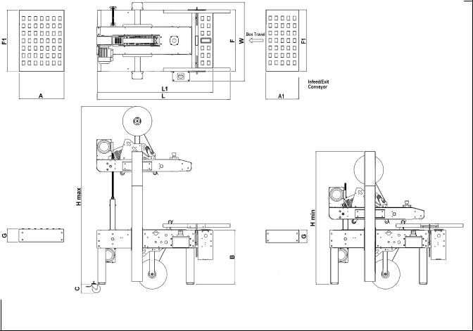
10. Machine Dimensions:
|
W |
L |
H |
A |
A1 |
B |
C** |
F |
F1 |
G |
T |
|
|
|
|
|
|
|
|
|
|
|
|
Minimum |
|
|
|
|
|
|
|
|
|
|
|
mm |
805 |
1360 |
1340 |
460 |
336 |
545 |
106 |
620 |
620 |
130 |
1640 |
(inches) |
(32) |
53.5 |
(52.8) |
(18.1) |
(13.2) |
(21.5) |
(4.2) |
(24.4) |
(24.4) |
(5.2) |
(64.6) |
|
|
|
|
|
|
|
|
|
|
|
|
Maximum |
|
|
|
|
|
|
|
|
|
|
|
mm |
-- |
-- |
1790 |
-- |
-- |
800 |
-- |
-- |
-- |
-- |
-- |
(inches) |
|
|
(70.5) |
|
|
(31.5) |
|
|
|
|
|
|
|
|
|
|
|
|
|
|
|
|
|
* Exit conveyor is optional ** Casters are optional
Weight – 193 kg [425 lbs.] crated (approximate) 170 kg [375 lbs.] uncrated (approximate)
11.Setup Recommendations:
•Machine must be level.
•Customer supplied infeed and exit conveyors (if used) should provide straight and level box entry and exit.
•Exit conveyors (powered or gravity) must convey sealed boxes away from machine.
8

Installation and Setup
Receiving And Handling
After the machine has been uncrated, examine the case sealer for damage that might have occurred during transit. If damage is evident, file a damage claim immediately with the transportation company and notify your 3M Representative.
Machine Setup
 WARNING
• To reduce the risk associated with mechanical and electrical hazards:
−Read, understand, and follow all safety and operating instructions before operating or servicing the case sealer.
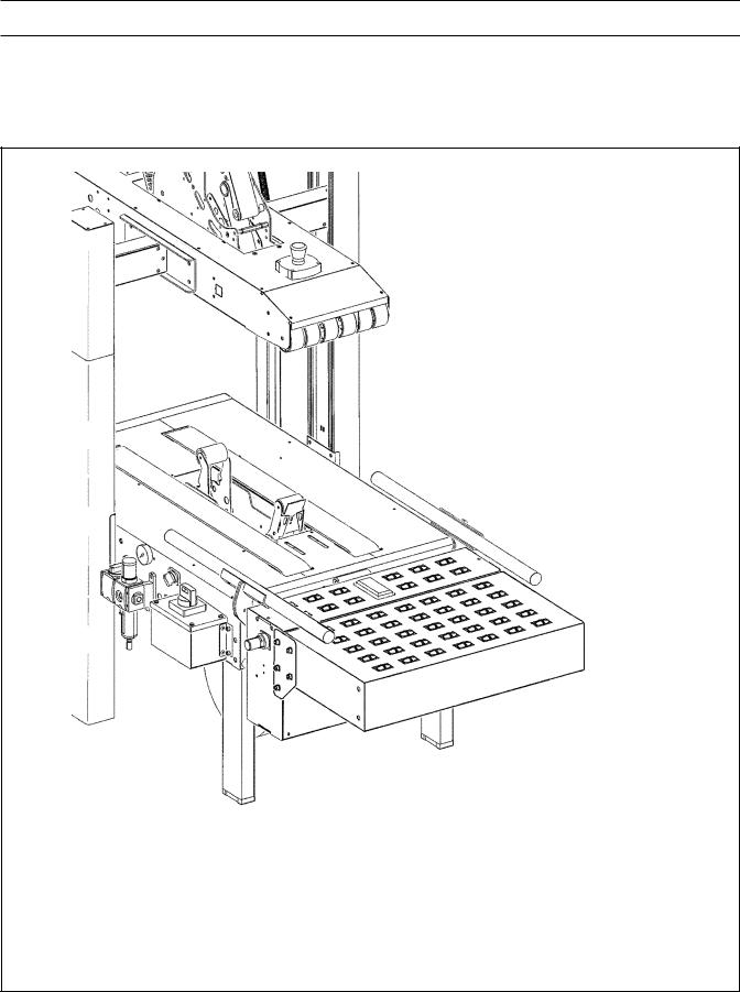
The following instructions are presented in the order recommended for setting up and installing the case sealer, as well as for learning the operating functions and adjustments. Following them step-by-step will result in thoroughly understanding the case sealer and installing it in a manner that best utilizes its many features. Refer to Figure 3-1 to identify the various components of the case sealer.
REQUIREDTOOLS
A 17 mm and 21 mm open-end wrench and a 17 mm hex socket wrench are provided with the machine.
The following customer-supplied tools are required for machine setup, maintenance, and adjustments.
•3 mm hex wrench
•4 mm hex wrench
•5 mm hex wrench
•6 mm hex wrench
•7 mm combination wrench
•8 mm combination wrench
•10 mm combination wrench
•13 mm combination wrench
•17 mm combination wrench
•#2 Phillips screwdriver
PACKAGING AND SEPARATE PARTS
1.Remove the staples from the shipping carton or cut around them.
Figure 2-1—Remove Staples
2.Remove the shipping carton from the pallet and from the machine.
Figure 2-2—r70 Frame Setup
 WARNING
• To reduce the risk associated with muscle strain:
−Use the appropriate rigging and material handling equipment when lifting or repositioning this equipment.
−Use proper body mechanics when removing or installing taping heads that are moderately heavy or awkward to lift.
9
Installation and Setup (Continued)
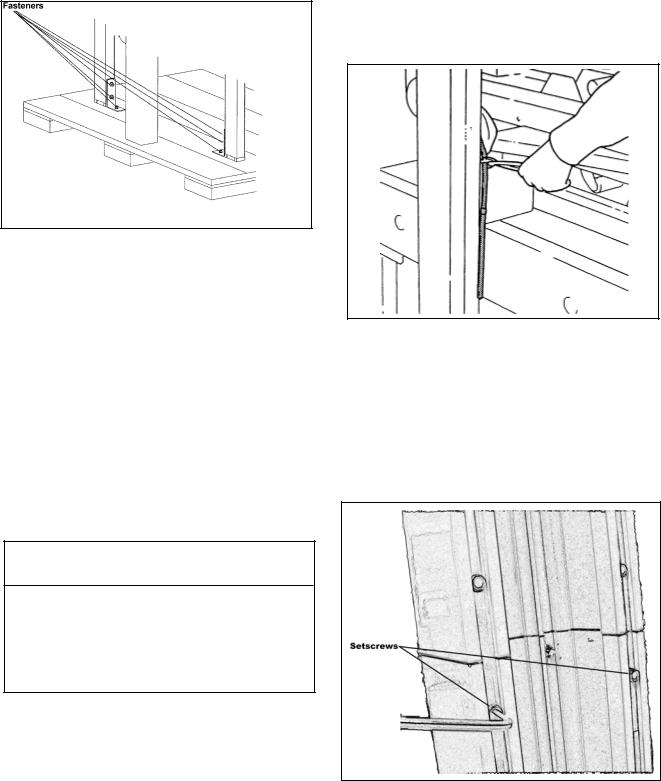
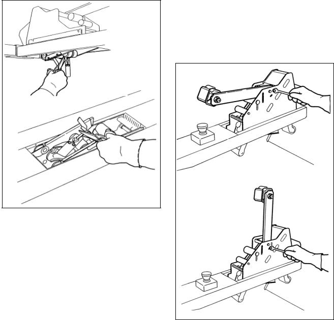
3.Using a 10 mm combination wrench, remove the fasteners that secure each of the case sealer legs to the pallet as shown in Figure 2-3.
Figure 2-3—Remove Fasteners
6.Cut the plastic straps that attach the top head to the frame as shown in Figure 2-4. Retain the tool and spare parts kit for later use.
4.Remove the leg height adjustment cap screws and replace with the cap screws from the tool kit. Remove and replace them one at a time to keep the inner threaded plate in position.
5.Remove the machine from the pallet and move it into position.
Important: Whenever the machine is lifted with a fork truck, ensure that the forks span completely across the machine frame and do not contact any wiring or mechanism under the machine frame. In some cases, the lower taping head may need to be removed to avoid damage.
Figure 2-4—Cut the Plastic Straps
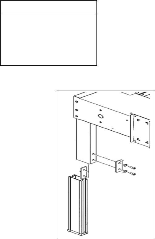
7.Assemble the column cap onto the column as shown in Figure 2-5.
8.Fasten the column setscrews as shown in Figure 2- 6.
 WARNING
• To reduce the risk associated with sharp blade hazards:
−Keep hands and fingers away from tape cutoff blades under orange blade guards. The blades are extremely sharp.
Figure 2-5—Column Cap Setscrews
10
Installation and Setup (Continued)
 WARNING
• To reduce the risk associated with muscle strain:
−Use the appropriate rigging and material handling equipment when lifting or repositioning this equipment.
INFEED CONVEYOR ASSEMBLY
1.Remove the conveyor and the package of parts from the carton.
2.Verify that the package contains two flat plates, ten M8 x 20 hex socket head screws, and ten M8 flat washers.
3.To assemble the infeed conveyor, refer to Figure 2-2 and locate the three bolt holes on the infeed end of the case sealer frame and the two bolt holes on the infeed conveyor.
4.Place the flat plates over the conveyor and the frame on each side and secure them with five M8
x20 screws and M8 washers.
5.Insert a M8 x 20 screw in each hole so that only
afew threads take hold.
Figure 2-2—Infeed Conveyor
CENTERINGGUIDES
1.Remove the two centering guides and four
M6 x 20 socket head screws from the package.
2.Using a 5 mm hex wrench, attach the centering guides to the rails with four M6 x 20 screws (two in each guide) as shown in
Figure 2-3.
Figure 2-3—Centering Guides
11
Installation and Setup (Continued)
MACHINE BED HEIGHT
The case sealer is equipped with four adjustable legs that are located at the corners of the machine frame. The legs can be adjusted to obtain different machine bed heights. See the "Specifications" section.
 WARNING
• To reduce the risk associated with muscle strain:
−Use the appropriate rigging and material handling equipment when lifting or repositioning this equipment.
−Use proper body mechanics when removing or installing taping heads that are moderately heavy or may be considered awkward to lift.
To adjust the machine bed height, do the following:
1.Use appropriate material handling equipment and blocking techniques to raise the machine frame to allow adequate leg adjustment.
2.Using a 6 mm hex wrench, loosen the socket head screws that hold the inner leg assembly to the machine as shown in Figure 2-10.
3.Adjust the leg length for the desired machine bed height. Adjust all four legs equally.
4.Retighten the screws.
Note: It is not necessary to fasten the machine to the floor.
TAPE LEG LENGTH
Taping heads are preset to apply 70 mm
[2.75 inches] long tape legs. To change tape leg length to 50 mm [2.0 inches], refer to Section II, "Special Setup Procedure—Changing the Tape Leg Length".
Figure 2-10—Machine Bed Height Adjustment
12
Installation and Setup (Continued)
ELECTRICALCONNECTIONANDCONTROLS
The electrical control box (with circuit breaker) and "On/Off" switch are located on the left side of the machine frame. See Figure 3-1. If desired, for operator convenience, the "On/Off" switch can be relocated to the right side of the machine frame. A standard three-conductor power cord with plug is provided at the back of the electrical control box. The receptacle providing this service shall be properly grounded. Before the power cord is plugged into a 115 Volt, 60 Hz outlet, verify that all packaging materials and tools are removed from the machine. Do not plug electrical cord into outlet until ready to run machine.
Use of an extension cord is not recommended. However, if one is needed for temporary use, it must have a wire size of 1.5 mm diameter [AWG 16 ], have a maximum length of 30.5 m [100 ft], and must be properly grounded.
 WARNING
• To reduce the risk associated with hazardous voltage:
−Position electrical cord away from foot and vehicle traffic.
Note: Machines outside the U.S. may be equipped with 220/240 Volt, 50 Hz systems or other electrical requirements compatible with local practice.
SPACEREQUIREMENTS
The left side of the machine must be a minimum of 1.0 m (39.4 inches) from the nearest wall.
The right side of the machine must be a minimum of 0.7 m (27.6 inches) from the nearest wall.
The machine requires a minimum of 2.7 m (106.3 inches) height.
OPERATORWORKINGPOSITION
Figure 2-11 illustrates the correct operator working position.
Figure 2-11—Operator Working Position
13

Installation and Setup (Continued)
PNEUMATICCONNECTION
Important: Use care when working with compressed air.
The case sealer requires a 5.2 bar gauge pressure 110 liter/min [75 PSIG], @ 21°C, 1.01 bar [3.75 SCFM] compressed air supply. As shown in Figure 3-1, an on/off valve, pressure regulator, and filter are provided to service the air supply.
Note: A precision regulator is used to balance the top drive assembly. Due to the selfrelieving feature of this regulator, a small amount of air continually vents to the atmosphere. This is normal and amounts to approximately 3 liter/min. [0.1 SCFM].
1.Read and remove safety tag from pneumatic "On/Off"valve.
2.Connect the main air supply line to the inlet side of the On/Off valve using the barbed fitting and hose clamp provided. The customer supplied air hose
(8 mm [5/16 inches] Inner Diameter) must be clamped tightly to the barbed fitting.
If another type of connector is desired, the barbed fitting can be removed and replaced with the desired 1/4-18 NPT threaded connector.
Always turn the air valve Off when the air supply line is being connected or disconnected.
3.Turn the air supply on by turning the air On/Off valve to On.
Note – The air valve has provisions for lock out/tag out according to plant regulations.
 WARNING
• To reduce the risk associated with impact hazards:
−Always use appropriate supporting means when working under the upper drive assembly
4.Raise the upper drive assembly to full Up position by turning the drive assembly raising switch clockwise.
14
Installation and Setup (Continued)
TAPING HEAD SETUP
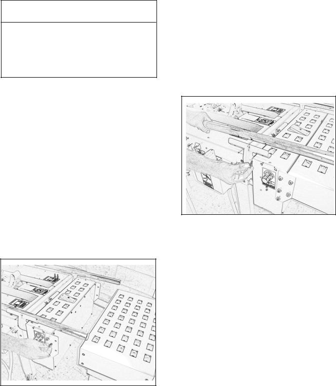
1.Cut the plastic ties holding the upper and lower taping heads in position, as shown in Figure 2-8. Hold taping head Buffing Roller while cutting the plastic tie. Allow buffing/applying arms to extend slowly.
Figure 2-8—Cut the Plastic Ties
2.Verify that the upper and lower taping heads move freely by pushing the buffing roller into the taping head.
3.Using a 10 mm open-end wrench, loosen the capscrew on the tape drum bracket assembly and move the assembly to the vertical position, as shown in Figure 2-9. Install additional capscrews from the tool kit. The tape drum bracket assembly can be pivoted as necessary to provide tape roll clearance from the floor or overheadobstacles.
Figure 2-9—Lower Tape Drum Bracket Position
INITIAL STARTUP OF CASE SEALER
After completing the "Installation and Setup" procedure, continue through "Operation" for tape loading and startup to ensure that the case sealer is properly adjusted to run boxes.
15
Operation
 WARNING
•To reduce the risk associated with mechanical and electrical hazards:
−Read, understand, and follow all safety and operating instructions before operating or servicing the case sealer
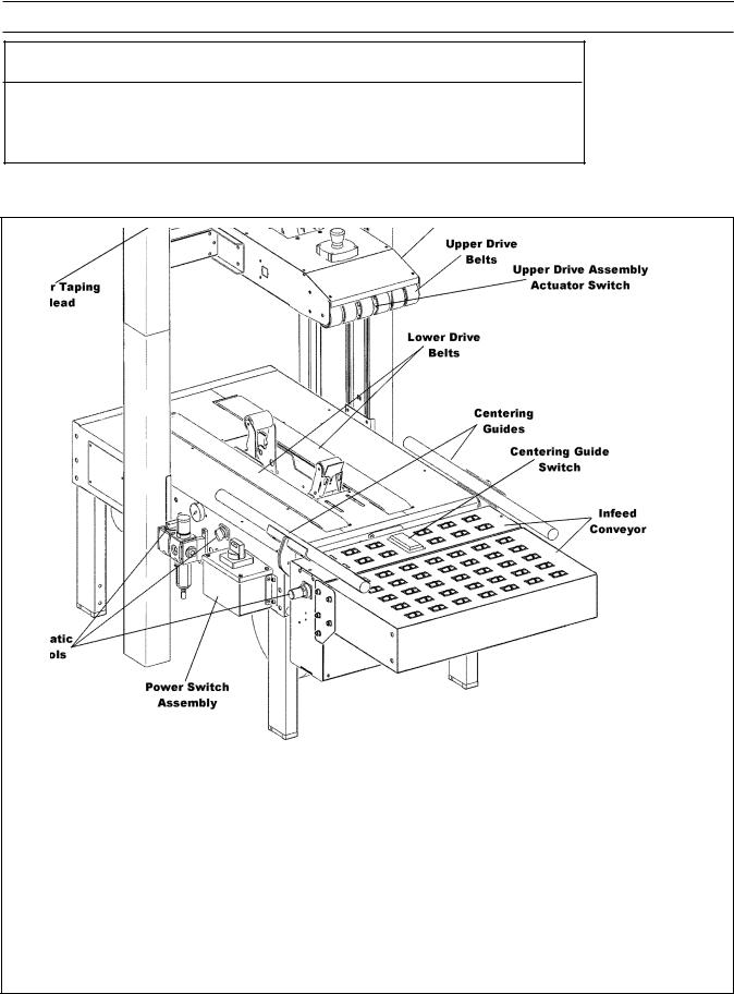
Refer to Figure 3-1 and 3-2 below to acquaint yourself with the various components and controls of the case sealer. Also see Figures 3-1 and 3-2 in Section II for taping head components.
Figure 3-1—r70 Case Sealer Components (Left Front View)
16
Operation (Continued)
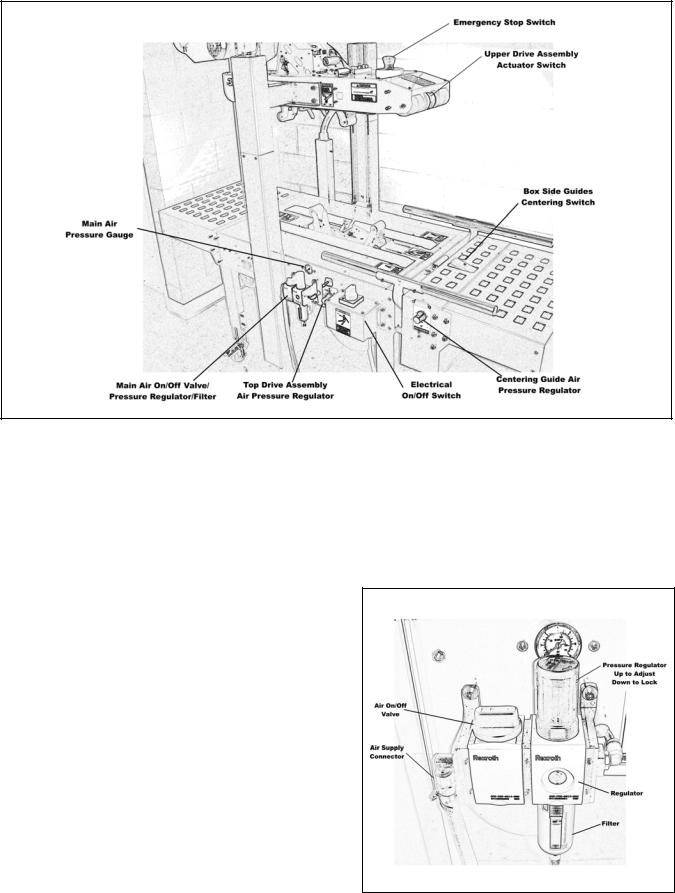
Figure 3-2—Controls, Valves and Switches
Electrical On/Off Switch (Figure 3-2)
The box drive belts are turned on and off with the electrical switch on the side of the machine frame.
The case sealer has a circuit breaker located in the electrical enclosure on the left side of the machine frame. If circuit becomes overloaded and circuit breaker trips, unplug the machine electrical cord and determine cause of overload. After two minutes, plug machine electrical cord into outlet and restart machine by rotating the On/Off switch to Off (O) then On (I).
Main Air On/Off Valve/Pressure Regulator/ Filter (Figure 3-3)
This set of pneumatic components controls, regulates and filters plant air supply to the two separate control circuits of the case sealer.
On/Off Valve (Figure 3-2)
On—turn arrows on switch toward the front of the machine; Off—turn arrows on switch toward the left side of the machine.
Note: Turning air supply off automatically bleeds air pressure from the case sealer air circuits.
Always turn off the air when machine is not in use, when servicing the machine, or when connecting or disconnecting air supply line.
Note: The air valve has provisions for lockout/ tagout according to plant regulations.
Figure 3-3—On/Off Valve/Regulator/Filter
17
Operation (Continued)
Pressure Regulator (Figure 3-3)
Regulates main air pressure to the machine to adjust pressure, pull knob up and turn; push down to lock setting.
Filter (Figure 3-3)
Removes dirt and moisture from plant air before it enters the case sealer pneumatic circuits. If water collects in bottom of bowl, unscrew the valve on the bottom of bowl to drain. When empty, retighten valve.
Emergency Stop Switch (Figure 3-2)
The machine electrical supply can be turned off by pressing the latching emergency stop switch. To restart machine, rotate emergency stop switch a quarter turn clockwise to releases switch latch. Restart machine by turning the switch to the "O" (Off) position then to "I" (On).
Upper Drive Assembly Actuator Switch
(Figure3-2)
This switch, when touched by the leading edge of a box , pneumatically raises the upper drive assembly to allow insertion of the box under the drive belts. As the box moves under the switch, releasing it, the upper drive assembly descends on the box and the drive belts convey the box through the machine. When switch is turned, the upper drive assembly rises. When the switch is released, the upper drive assembly descends to its rest position.
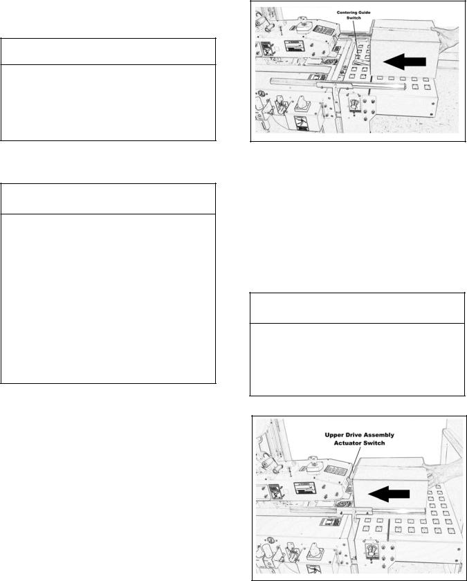
Centering Guide Switch (Figure 3-7) This pneumatic switch controls the box
centering guides. When switch is activated by a box entering the case sealer, the centering guides close (centering the box), and released (after box passes over switch), the guides open.
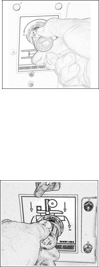
Air Pressure Regulator, Centering Guide Force Adjustment (Figure 3-4)
This regulator is used to adjust centering guides according to weight of boxes. Pressure should be adequate to center boxes, but low enough to allow easy pushing of boxes under taping head.
To adjust the regulator setting, pull the knob outward, rotate the knob to the desired setting. Push the knob inward to lock it and prevent unintentional adjustment.
Figure 3-4—Air Regulator, Centering Guides
Air Pressure Regulator, Top Drive Assembly Force Adjustment (Figure 3-5)
Set nominally to control the "down" movement of top drive assembly and the pressure exerted against the box as shown in Figure 3-5. The regulator setting is changed as necessary for the boxes being sealed to provide adequate drive belt pressure against the box to positively convey the boxes through the machine. If the boxes stop or hesitate while being conveyed, decrease the regulator pressure. This increases the drive belt force on the box for more friction between the box and drive belts. Adjust the pressure setting as necessary to get continuous movement of boxes through the machine.
Figure 3-5—Air Regulator/Gauge, Top Drive
Assembly
18
Operation (Continued)
For boxes which are fully packed with products that support the top flaps, the adjustment of this regulator is not critical since the boxes can support the pressure of the upper frame (drive belts) at a wide range of regulator settings. However, if under-filled or fragile boxes are sealed, this regulator can be used to set the upper frame pressure to a reduced level that is still adequate to positively convey the box and to prevent damage of boxes. The regulator setting can be locked by pushing the knob inward.
Note: A precision regulator is used to balance the top drive assembly. Due to the self relieving feature of this regulator a small amount of air will continually vent to the atmosphere. This is normal and amounts to approximately 3 liter/min
[0.1 SCFM ].
Main Air Pressure Gauge (Figure 3-2)
Indicates main air regulator pressure setting. Air regulator should be adjusted so gauge reads 5.2 bar gauge pressure [75 PSIG].
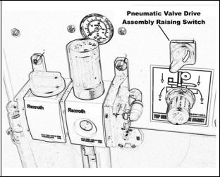
Pneumatic Valve, Drive Assembly Raising Switch (Figure 3-6)
The Pneumatic Valve Drive Assembly Raising Switch is used to hold the upper drive assembly to its fully raised position for tape threading and maintenance.
To raise the drive assembly, turn the switch to the right. To lower the drive assembly to its fully lowered position, turn the switch to the left.
Figure 3-6—Mechanical Latch, Upper
Drive Assembly
19
Operation (Continued)
Tape Loading/Threading
See Section II.
 WARNING
• To reduce the risk associated with muscle strain:
−Use proper body mechanics when removing or installing taping heads that are moderately heavy or may be considered awkward to lift.
Theory of Operation
 CAUTION
•To reduce the risk associated with pinches and entanglement hazards:
−Always feed boxes into the machine by pushing only from the end of the box.
−Keep hands clear of the upper head support assembly as boxes are transported through the machine.
•To reduce the risk associated with pinches and impact hazards:
−Keep away from the pneumatically controlled upper drive assembly and box centering guides when air and electric supplies are on.
The air supply powers movement of the centering guides and upper drive assembly to automatically adjust the case sealer to the box size being sealed as follows:
1.A box centering switch in the center of the infeed roller conveyor actuates movement of the centering guides. When the operator pushes a box onto the infeed conveyor, as shown in Figure 3-7, the lever is depressed causing the air cylinder powered centering guides to move inward, centering the box.
Figure 3-7—Centering Guide Switch
2.Once the box is centered by the guides, the operator pushes the box against the raising switch on the upper drive assembly, as shown in Figure 3-8, two air cylinders raise the upper drive assembly. The upper taping head will continue to rise above the box height so the operator can insert the box underneath the upper drive belts.
 CAUTION
•To reduce the risk associated with pinches and entanglement hazards:
−Keep hands clear of the upper head support assembly as boxes are transported through the machine
Figure 3-8—Upper Drive Assembly Actuator
Switch
20
Operation (Continued)
 CAUTION
•To reduce the risk associated with pinches and entanglement hazards:
−Keep hands, hair, loose clothing, and jewelry away from moving belts and taping heads
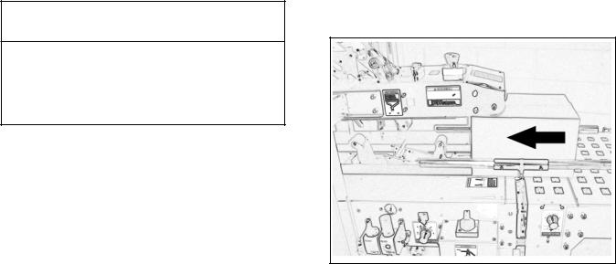
3.Once the box is pushed under the upper taping head, the upper drive assembly actuator switch is releases to lower the upper drive assembly to descend onto the box top, as shown in
Figure 3-9, allowing the drive belts to convey the box through the upper and lower taping heads for application of the tape seals.
4.As the box is conveyed through the machine, the centering guide switch is released causing the centering guides to return to their full open position, ready for insertion of the next box.
5.Once the box is conveyed from under the upper taping head, the upper drive assembly descends to its rest position, ready for insertion of the next box.
At this point it is recommended that the centering guides and upper drive assembly switches be manually actuated to better understand their functions. Depress the centering guide switch to close the guides. Release the switch to open the guides. Depress the upper drive assembly raising switch to raise the upper drive assembly. Release the upper drive assembly raising switch to lower the drive assembly.
Box Sealing
1. Turn main air valve to (On).
Important: Before turning drive belts on, be sure no tools or other objects are on the conveyor bed.
2.Turn the switch on side of machine frame to start drive belts.
3.Feed boxes to machine. Always allow previous box to exit machine BEFORE feeding next box.
4.Turn air and electrical supplies "Off" when machine is not in use.
5.Reload and thread tape as necessary.
6.Be sure machine is cleaned and lubricated according to recommendations in "Maintenance"
section of this manual. |
21 |
|
Figure 3-9—Box Conveyed Through Machine
Machine or taping head adjustments are described in "Adjustments" Section I for machine or Section II for taping heads.
Note: Box drive motors are designed to run at a temperature somewhat above ambient room temperature. A motor may feel hot to the touch during normal operation.

Maintenance
The case sealer has been designed for long, trouble free service. The machine performs best when it receives routine maintenance and cleaning. Machine components that fail or wear excessively should be promptly repaired or replaced to prevent damage to other portions of the machine or to the product.
 WARNING
•To reduce the risk associated with mechanical and electrical hazards:
−Turn electrical and air supply off and disconnect before performing any adjustments, maintenance, or servicing the machine or taping heads.
•To reduce the risk associated with impact hazards:
−Always use appropriate supporting means when working under the upper drive assembly.
Cleaning
Note – Never attempt to remove dirt from the machine by blowing it out with compressed air. This can cause the dirt to be blown inside the motor and onto sliding surfaces which may cause premature equipment wear. Never wash or subject equipment to conditions causing moisture condensation on components. Serious equipment damage could result.
Regular slotted containers produce a great deal of dust and paper chips when processed or handled in equipment. If this dust is allowed to buildup on machine components, it can cause component wear and overheating of drive motor. The dust buildup can best be removed from the machine by a shop vacuum. Depending on the number and type of boxes sealed in the case sealer, this cleaning should be done approximately once per month. If the boxes sealed are dirty, or if the environment in which the machine operates is dusty, cleaning on a more frequent basis may be necessary. Excessive dirt buildup that cannot be removed by vacuuming should be wiped off with a damp cloth.
Lubrication
The machine bearings, including the drive motor, are permanently lubricated and sealed and do not require additional lubricant.
22
 Loading...