


SuperStack II Hub 10
Table of contents
 Loading...
Related Standards
The Hub 10 Telco has been designed to conform to the following
standards:
Physical
Electrical
Hub 10 Telco only
Hub 10 Telco & Management Module
Environmental
T
ECHNICAL
I
NFORMATION
Functional
ISO 8802/3, IEEE 802.3
Safety
UL 1950, EN 60950, CSA 22.2 #950
EMC
EN 55022 Class B, EN 50082-1, FCC Part 15 Class A,
CSA C108.8 Class A
(screened cables must be used to ensure
compliance with these standards)
Environmental
EN 60068 (IEC 68)
Width
440mm (17.3 ins)
Depth
224mm (8.8 ins)
Height
44mm (1.7 ins) or 1U
Weight
2.6kg (5.7lb)
Mounting
free standing,
or 19" rack or wall mounted using kit supplied
Power Inlet
IEC 320
Fuse Protection
2 Amps
Power Consumption
22 VA
Power Dissipation
73 BTU/hr
Power Inlet
IEC 320
Fuse Protection
2 Amps
Power Consumption
30 VA
Power Dissipation
100 BTU/hr
Operating Temperature
0-50°C (32-122°F)
Humidity
0-90% (non-condensing)
SuperStack™ II Hub 10
Telco (3C16672A)
User Guide
DUA1667-2AAA03
Please read the following safety information carefully before
installing the Hub 10 Telco.
WARNING:
Installation and removal of the unit must be
carried out by
qualified personnel only
.
■
Connect the unit to an earthed power supply to ensure
compliance with safety standards.
■
It is essential that the socket outlet is installed near to the unit
and is easily accessible. You can only disconnect the unit by
removing the supply plug from the outlet.
■
This unit operates under SELV conditions (Safety Extra Low
Voltage) according to IEC 950, the conditions of which are
maintained only if the equipment to which it is connected is also
operational under SELV.
■
The appliance coupler, i.e., the connector to the device itself and
not the wall plug, must have a configuration for mating with an
EN60320/IEC320 appliance inlet.
France and Peru Only
This unit cannot be powered from IT
†
supplies. If your supplies are of IT
type, this unit should be powered by 230V (2P+T) via an isolation
transformer ratio 1:1, with the secondary connection point labelled
Neutral, connected directly to Earth (Ground).
†
Impédance à la terre
Power Cord Set
This must be approved for the country where it will be used.
Veuillez lire à fond l'information de la sécurité suivante avant
d'installer le Hub 10 Telco.
AVERTISSEMENT:
L'installation et l'enlèvement de l'unité
doivent être faits seulement par le personnel qualifié.
■
Brancher l'unité à une source de courant mise à la terre pour
assurer la conformité aux normes de sécurité.
■
C'est essentiel que le socle soit installé près de l'unité et soit
accessible. Vous pouvez seulement débrancher l'unité en
enlevant la fiche d'alimentation de la prise de courant.
■
Cette unité marche sous les conditions SELV (Safety Extra Low
Voltage) conformément à IEC950, ces conditions sont maintenues
seulement si le matériel auquel elle est branchée, est aussi en
exploitation sous SELV.
■
Le socle de connecteur, c'est-à-dire, le connecteur à l'appareil
lui-même et non pas la prise murale, doit avoir une configuration
pour le branchement avec une admission d'appareil
EN60320/IEC320.
Seulement Pour La France et Le Pérou
Cette unité ne peut pas être mise en marche des sources de courant IT
(Impédance à la terre). Si vos sources de courant sont de type IT, cette
unité doit être alimentée par 230V (2P+T) via un rapport de
transformation d'isolation de 1:1, avec un point de connexion secondaire
étiqueté Neutre, branché directement à la Terre (à la Masse).
La Cordon d'Alimentation Surmoulé
Celui-ci doit être approuvé pour le pays auquel il sera utilisé.
Bitte unbedingt vor dem Einbauen des Hub 10 Telco Einheit die
folgenden Sicherheitsanweisungen durchlesen.
Ein- und Ausbau des Gerätes ist
nur von Fachpersonal
vorzunehmen.
■
Das Gerät an geerdete Stromversorgung anschließen, um eine
Übereinstimmung mit den Sicherheitsbestimmungen zu
gewährleisten.
■
Es ist wichtig, daß der Netzstecker sich in unmittelbarer Nähe zum
Gerät befindet und leicht erreichbar ist. Das Gerät kann nur durch
Herausziehen des Verbindungssteckers aus der Steckdose vom
Stromnetz getrennt werden.
■
Das Gerät wird mit Sicherheits-Kleinspannung nach IEC 950 (SELV
= Safety Extra Low Voltage) betrieben. Angeschloßen werden
k
ö
nnen nur Geräte, die ebenfalls nach SELV betrieben werden.
■
Die Anordnung der Gerätsteckvorrichtung, d.h. die
Steckverbindung am Gerät selbst im Gegensatz zum Wandstecker,
muß in den EN60320/IEC320 Zuführungsstecker am Gerät passen.
■
Der Anschlußkabelsatz muß mit den Bestimmungen des Landes
übereinstimmen, in dem er verwendet werden soll.
S
AFETY
I
NFORMATION
USA and
Canada
■
The cord set must be UL-approved and CSA certified.
■
The minimum specifications for the flexible cord are:
No. 18 AWG
Type SV or SJ
3-conductor
■
The cord set must have a rated current capacity of at
least 10A.
■
The attachment plug must be an earth-grounding
type with a NEMA 5-15P (15A, 125V) or NEMA 6-15P
(15A, 250V) configuration.
Denmark
■
The supply plug must comply with Section 107-2-D1,
Standard DK2-1a or DK2-5a.
Switzerland
■
The supply plug must comply with SEV/ASE 1011.
L’
INFORMATION
DE
S
ÉCURITÉ
I
MPORTANTE
USA et
le
Canada:
■
Le cordon surmoulé doit être UL Certifié et CSA Certifié.
■
Les spécifications minimales pour le cordon souple sont:
No. 18 AWG
Type 5V ou SJ
3-conducteur
■
Le cordon surmoulé doit avoir une capacité de courant
calculée au moins de 10A.
■
La fiche de fixation doit être un type mis à la terre avec
une configuration NEMA 5-15P (15A, 125V) ou NEMA
6-15P (15A, 250V).
W
ICHTIGE
S
ICHERHEITSINFORMATIONEN
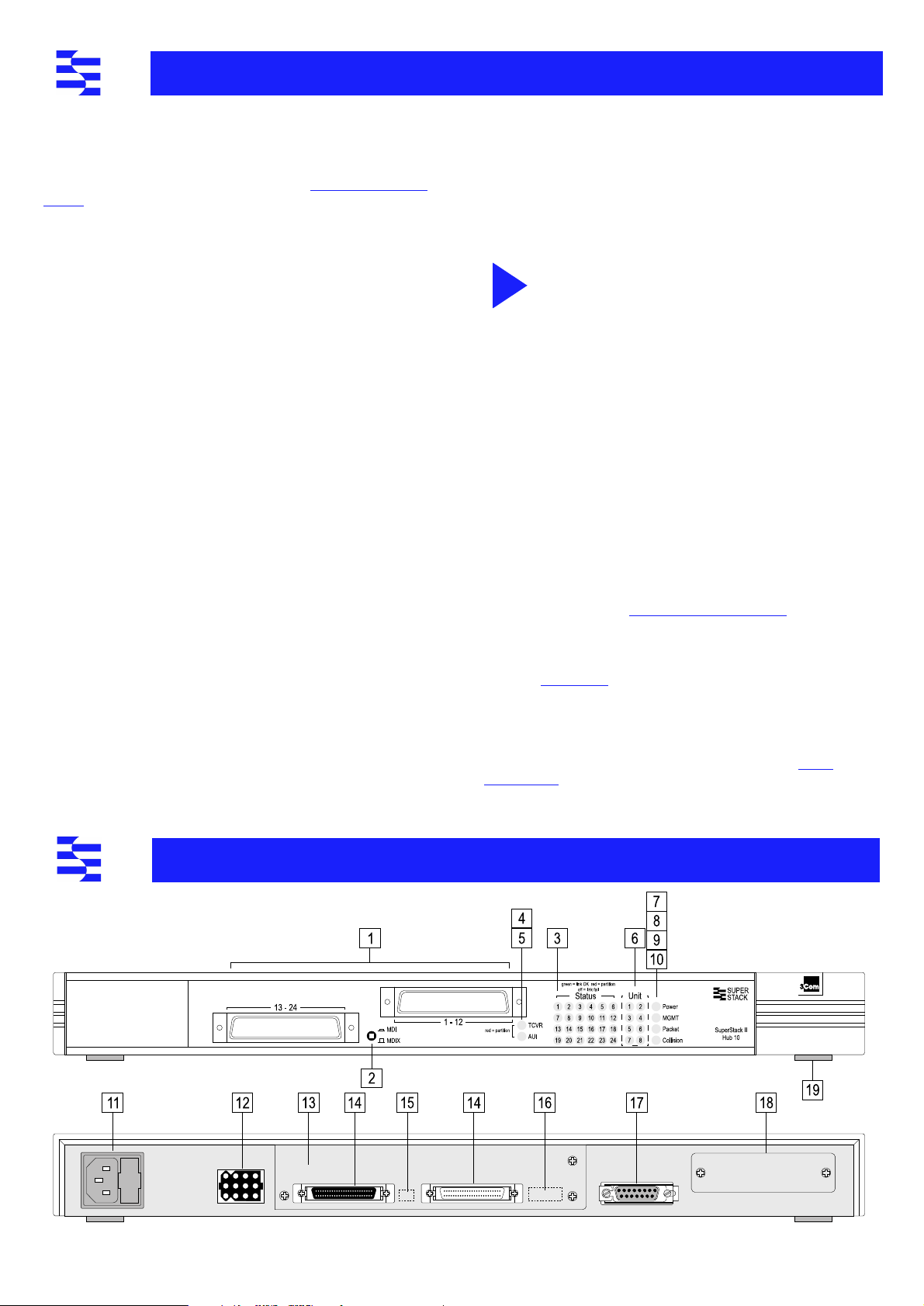
The SuperStack™ II Hub 10 Telco (3C16672A) has two 12 port Telco
connectors on the front panel providing Ethernet TP port connections,
and an AUI port on the rear panel. The rear panel also has a slot for a
3Com Transceiver Module or Bridge MicroModule: if fitted the module
will operate in addition to the AUI port. A range of different media
Transceiver Modules is available from 3Com (see
“
Products and Bulletin
Boards
”
).
The Hub 10 Telco can be stand-alone or linked with other Hub 10,
LinkBuilder FMS II, FMS, 10BT or 10BTi units to form a stack of units of
different media. Stacking units gives you the benefit of a higher port
count while the stack is still seen by the network as a single 802.3
repeater.
The Hub 10 Telco is suited for use in the office where it can be
wall-mounted, rack-mounted, or free standing. Alternatively, the unit can
be rack-mounted in a wiring closet or equipment room. A mounting kit
is supplied.
The Hub 10 Telco can be powered either from the AC mains supply, or
through an optional 3Com Redundant Power System (3C565047) to
provide a more reliable supply. Contact your local supplier for details.
Repeater Functions
The Hub 10 Telco has been designed to conform to the IEEE 802.3
standard for Local Area Networks. The unit provides all the standard
functions of an 802.3 repeater, including:
■
Signal retiming
■
Preamble regeneration
■
Fragment extension
■
Automatic partition/reconnection
Management
A SuperStack II Hub 10 Management Module (3C16630A) or Advanced
RMON Module (3C16632) can be fitted to the Hub 10 Telco to provide
f
ull SNMP management
, including statistics, resilient links and security
features
. Only one Management Module or Advanced RMON Module is
required for each stack. Refer to the guides accompanying the module
for details on how to manage an Hub 10 unit or stack.
Resilience and Security
H
ub 10 Management Module (3C16630A) and Hub 10 Advanced RMON
Module (3C16632) offer resilience
and security f
eatures.
Up to 16 resilient link pairs can be configured via management software.
To avoid the creation of loops during power-up, Hub 10 units provide a
Disable On Boot switch. If this switch is set to disable, all TP ports on the
unit will be disabled during power-up until they are correctly configured
and enabled by management software. This is only necessary on units
which have ports assigned as standby. Standby ports in resilient link
pairs can only be configured on SuperStack II Hub 10 or LinkBuilder
FMS II units.
Security features are described in the manual which comes with your
Hub 10 Management Module.
By disabling ports on boot up and enabling them with management
software, you provide extra security for your unit.
During the power up sequence, the main ports (on the front
panel) will be disabled, BUT the AUI and Transceiver Module
ports will be enabled for periods up to 1 second. During this
brief moment, the AUI and Transceiver Module ports will NOT
be secure.
Network Connections
The Hub 10 Telco has been designed for use with the majority of known
Telco connectors.
Cable fixings have been supplied for holding the Telco cables to the
unit. There are locations for these fixings to the left of the Telco
connectors.
In the unlikely event that your Telco connector will not connect fully to
the Hub 10 Telco, we recommend that you:
■
Use a connector extension
■
Use a Telco connector with a different cable approach
You can connect any 802.3 transceiver to the unit using an AUI cable
connected to the AUI port on the rear panel. Alternatively, you can fit
one of the 3Com Transceiver Modules or a Bridge MicroModule into the
slot on the rear panel (see
“
Products and Bulletin Boards
”
).
You can connect the Hub 10 Telco to any other 10Base-T unit using port
24, to form an inter-repeater link. You must switch port 24 to MDI to
bypass the internal cross-over normally implemented by 10Base-T unit
ports. See
“
MDI Switch
”
.
Important
To manage this hu b, you
may n
eed
a new v
ersion of the agent
software
installed on y
our Management Module.
See
“
Stack
Management
”
for details.
Numbered elements in this diagram refer to numbered sections in the text.
The numbers, in bold, are used as references in the text.
I
NTRODUCTION
H
OW
TO
U
SE
THE
H
UB
10
i
Loading...