


 Loading...
®
http://www.3com.com/
Installing the
SuperStack® II NETBuilder®
Token Ring and FRAD
Bridge/Router
Models 32x and 52x
Part No. 09-0848-003
Published May 1997

3Com Corporation 5400 Bayfront Plaza Santa Clara, California 95052-8145
Copyright © 3Com Corporation, 1997. All rights reserved. No part of this documentation may be reproduced in any form or by any means or used to make any derivative work (such as translation, transformation, or adaptation) without permission from 3Com Corporation.
3Com Corporation reserves the right to revise this documentation and to make changes in content from time to time without obligation on the part of 3Com Corporation to provide notification of such revision or change.
3Com Corporation provides this documentation without warranty of any kind, either implied or expressed, including, but not limited to, the implied warranties of merchantability and fitness for a particular purpose. 3Com may make improvements or changes in the product(s) and/or the program(s) described in this documentation at any time.
UNITED STATES GOVERNMENT LEGENDS:
If you are a United States government agency, then this documentation and the software described herein are provided to you subject to the following restricted rights:
For units of the Department of Defense:
Restricted Rights Legend: Use, duplication, or disclosure by the Government is subject to restrictions as set forth in subparagraph (c) (1) (ii) for Restricted Rights in Technical Data and Computer Software Clause at 48 C.F.R. 52.227-7013. 3Com Corporation, 5400 Bayfront Plaza, Santa Clara, California 95052-8145.
For civilian agencies:
Restricted Rights Legend: Use, reproduction, or disclosure is subject to restrictions set forth in subparagraph
(a) through (d) of the Commercial Computer Software - Restricted Rights Clause at 48 C.F.R. 52.227-19 and the limitations set forth in 3Com Corporation’s standard commercial agreement for the software. Unpublished rights reserved under the copyright laws of the United States.
If there is any software on removable media described in this documentation, it is furnished under a license agreement included with the product as a separate document, in the hard copy documentation, or on the removable media in a directory file named LICENSE.TXT. If you are unable to locate a copy, please contact 3Com and a copy will be provided to you.
Unless otherwise indicated, 3Com registered trademarks are registered in the United States and may or may not be registered in other countries.
3Com, NETBuilder, and SuperStack are registered trademarks of 3Com Corporation. 3TECH is a trademark of 3Com Corporation. 3ComFacts is a service mark of 3Com Corporation.
CompuServe is a registered trademark of CompuServe, Inc. IBM is a registered trademark of International Business Machines Corporation. AppleTalk is a registered trademark of Apple Corporation. Banyan and VINES are registered trademarks of Banyan Systems. UNIX is a registered trademark in the United States and other countries, licensed exclusively through X/Open Company Limited. XNS is a trademark of Xerox Corporation. Siemens and EWSD are registered trademarks of Siemens Aktiengesellschaft. AT&T and 5ESS are registered trademarks of American Telephone and Telegraph. DMS is a registered trademark of Nothern Telecom Limited.
Other brand and product names may be registered trademarks or trademarks of their respective holders.
Guide written by Ramona Boersma. Edited by Amy Guzules. Technical illustration by Debra Knodel. Production by Ramona Boersma.
Electromagnetic Compatibility Information
Classes
Various national agencies (in the United States, The Federal Communications Commission (FCC)) govern the levels of electromagnetic emissions from digital devices. Electromagnetic emissions can interfere with radio and television transmission. To reduce the risk of harmful interference these agencies have established requirements for manufacturers of digital devices
The manufacturer of a digital device must test and label a product to inform an end-user of the maximum emission level from the product when used in accordance with its instructions. The emission levels encountered are classified as Class A or Class B. A system that meets the Class A requirement can be marketed for use in an industrial or a commercial area. A system that meets the more stringent Class B requirement can be marketed for use in a residential area in addition to an industrial or a commercial area.
The end user is generally held responsible for ensuring that his system is suitable for its environment as stated in the above paragraph and bears the financial responsibility for correcting any harmful interference.
ii

Modifications
Modifications or changes made to this device, and not approved by 3Com, may void the authority granted by the FCC, or other such agency, to operate this equipment.
Shielded Cables
Connections between 3Com equipment and other equipment and peripherals must be made using shielded cables in order to maintain compliance with FCC, and other agency, electromagnetic frequency emissions limits. This statement does not apply to the ISDN cable or 10BASE-T cables.
Federal Communications Commission Notice
This equipment has been tested and found to comply with the limits for a Class A digital device, pursuant to Part 15 of the FCC rules. These limits are designed to provide reasonable protection against harmful interference when the equipment is operated in a commercial environment. This equipment generates, uses and can create radio frequency energy and, if not installed and used inaccordance with the instruction manual, may cause harmful interference to radio communications. Operation of this equipment in a residential area can cause harmful interference in which case the user will be required to correct the interference at his own expense.
Canadian Notice
This digital apparatus does not exceed the Class A limits for radio noise emissions from digital apparatus set out in the interference-causing equipment standard entitled “Digital Apparatus,” ICES-003 of the Department of Communications.
Avis Canadien
Cet appareil numérique respecte les limites bruits radioélectriques applicables aux appareils numériques de Classe A prescrites dans la norme sur le matériel brouilleur: “Appareils Numériques”, NMB-003 édictée par le ministre des Communications.
Japanese Notice
Type Approval Information
This apparatus has been approved for use for connection to the following public telecommunication services: ISDN basic access, X.25 (V.24, V.36, and X.21), X.21 leased lines, X.21bis leased lines (V.24 and V.36). Any other usage will invalidate the approval of the apparatus if as a result it then ceases to conform against the standards against which approval was granted.
Notice
The Industry Canada label identifies certified equipment. This certification means that the equipment meets certain telecommunications network protective, operational, and safety requirements. The Department does not guarantee the equipment will operate to the users’ satisfaction.
Before installing this equipment, users should ensure that it is permissible to be connected to the facilities of the local telecommunications company. The equipment must also be installed using an acceptable method of connection. In some cases, the inside wiring associated with a single line individual service may be extended by means of a certified connector assembly. The customer should be aware that compliance with the above conditions may not prevent degradation of service in some situations.
Repairs to certified equipment should be made by an authorized Canadian maintenance facility designated by the supplier. Any repairs or alterations made by the user to this equipment, or equipment malfunctions, may give the telecommunications company cause to request the user to disconnect the equipment.
Users should ensure for their own protection that the electrical ground connections of the power utility, telephone lines, and internal metallic water pipe system, if present, are connected together. This precaution may be particularly important in rural areas.
CAUTION: Users should not attempt to make electrical ground connections by themselves, but should contact the appropriate inspection authority or an electrician, as appropriate.
iii

CE Notice
Marking by the following symbol 


 indicates compliance of this equipment with the EMC and Telecom Directives of the European Community. Such marking is indicative that this equipment meets or exceeds the following technical standards:
■EN 55022 — Limits and methods of measurement of radio interference characteristics of information technology equipment.
■EN 50082-1 — Electromagnetic compatibility – generic immunity standard part 1: residential, commercial, and light industrial.
■I-CTR2 — For connection to X.25 packet switched services and X.21 leased lines.
■I-CTR3 — For models with ISDN interfaces: connection to basic rate ISDN services.
iv

CONTENTS
ABOUT THIS GUIDE
|
Conventions |
1 |
|
|
|
|
|
|
|
||||
1 INSTALLING THE HARDWARE |
|
|||||
|
Required Equipment |
1-1 |
|
|
|
|
|
Mounting 1-3 |
|
|
|
|
|
|
Rack-Mount Kit |
1-3 |
|
|
|
|
|
Installing on a Tabletop |
1-3 |
|
|
||
|
Stacking with Brackets |
1-4 |
|
|
||
|
Installing in a Rack |
1-4 |
|
|
||
|
Cabling the Connectors |
1-5 |
|
|
||
|
Cabling the LAN Connector (Models 323, 327, and 52x) 1-6 |
|||||
|
Cabling the ISDN Connector (Model 52x) 1-6 |
|||||
|
Cabling the Serial Connectors |
1-7 |
||||
|
Models 32x (DTE mode) |
1-8 |
|
|||
|
Models 32x (DCE-like mode) |
1-8 |
||||
|
Models 52x (DTE mode) |
1-9 |
|
|||
|
Models 52x (DCE-like mode) |
1-9 |
||||
|
Attaching a Redundant Power System |
1-10 |
||||
|
Connecting a PC, Terminal, or Modem 1-11 |
|||||
|
Shutting Down |
1-12 |
|
|
|
|
|
|
|
|
|
|
|
2 OVERVIEW |
|
|
|
|
|
|
|
Model Features |
2-1 |
|
|
|
|
|
Chassis Panels |
2-1 |
|
|
|
|
|
LEDs 2-3 |
|
|
|
|
|
|
Hardware Interrupt Switch |
2-3 |
|
|
||
v

|
Connectors and Cables |
2-3 |
|
|
|
|
||
|
Console Cables |
2-3 |
|
|
|
|
|
|
|
PC Cable |
2-4 |
|
|
|
|
|
|
|
Terminal Cable |
2-5 |
|
|
|
|
|
|
|
Modem Cable |
2-6 |
|
|
|
|
|
|
|
LAN Connectors and Cables |
2-6 |
|
|
|
|||
|
UTP Connector and Cable |
2-6 |
|
|
||||
|
STP Connector and Cable |
2-7 |
|
|
|
|||
|
Cabling Standards |
2-8 |
|
|
|
|
||
|
Serial Cables |
2-9 |
|
|
|
|
|
|
|
V.35 to V.35 DCE Cable (32x) |
2-9 |
|
|||||
|
V.35 to V.35 Direct Connect Cable (32x) |
2-10 |
||||||
|
UNIVERSAL to V.35 Adapter Cable |
2-11 |
||||||
|
UNIVERSAL to V.35 Direct Connect Cable |
2-12 |
||||||
|
UNIVERSAL to RS-449/V.36 DCE Cable |
2-13 |
||||||
|
UNIVERSAL to RS-449/V.36 Direct Connect Cable 2-14 |
|||||||
|
UNIVERSAL to RS-232 DCE Cable |
2-15 |
|
|||||
|
UNIVERSAL to RS-232 Direct Connect Cable 2-16 |
|||||||
|
RS-232 to RS-232 DCE Cable |
2-17 |
|
|||||
|
RS-232 to RS-232 Direct Connect Cable |
2-18 |
||||||
|
UNIVERSAL to X.21 Adapter Cable |
2-19 |
||||||
|
ISDN Cable (Model 52x ) |
2-20 |
|
|
|
|||
|
Physical Specifications |
2-21 |
|
|
|
|
||
3 |
|
|
|
|
|
|
||
UPGRADING MEMORY |
|
|
|
|
|
|||
|
Removing the Cover |
3-1 |
|
|
|
|
|
|
|
Installing Memory |
3-2 |
|
|
|
|
|
|
|
Reinstalling the Cover |
3-3 |
|
|
|
|
||
4 |
|
|
|
|
|
|
|
|
TROUBLESHOOTING |
|
|
|
|
|
|
||
|
Troubleshooting During the Test Phase |
|
4-2 |
|
||||
|
Troubleshooting During the Load Phase |
4-2 |
|
|||||
|
LED Meanings 4-3 |
|
|
|
|
|
|
|
Troubleshooting the Token Ring Connection 4-4
vi

A PROVISIONING YOUR ISDN LINE
|
Ordering North American ISDN BRI Services |
A-1 |
||||
|
North American Switch Provisioning Tables |
A-3 |
||||
|
AT&T 5ESS Switch |
A-4 |
|
|
|
|
|
AT&T 5ESS Custom Switch |
A-5 |
|
|
||
|
DMS 100 and National ISDN |
A-6 |
|
|||
|
Siemens EWSD Switch |
A-7 |
|
|
|
|
|
SPIDs A-7 |
|
|
|
|
|
|
NT1s and Power Supplies |
A-8 |
|
|
|
|
|
Ordering German ISDN BRI Services |
A-9 |
|
|||
|
|
|
|
|
|
|
B TECHNICAL SUPPORT |
|
|
|
|
||
|
Online Technical Services |
B-1 |
|
|
|
|
|
World Wide Web Site |
B-1 |
|
|
|
|
|
3Com Bulletin Board Service |
B-1 |
|
|
||
|
Access by Analog Modem |
B-2 |
|
|||
|
Access by Digital Modem |
B-2 |
|
|
||
|
3ComFacts Automated Fax Service |
B-2 |
|
|||
|
3ComForum on CompuServe Online Service B-3 |
|||||
|
Support from Your Network Supplier |
B-3 |
|
|||
|
Support from 3Com |
B-4 |
|
|
|
|
|
Returning Products for Repair |
B-5 |
|
|
||
INDEX
3COM CORPORATION LIMITED WARRANTY
vii

viii

ABOUT THIS GUIDE
This guide includes complete hardware installation and cabling information for your SuperStack® II NETBuilder® bridge/router model 32x or 52x.
This guide is for the following audience:
■Inexperienced end users configuring their first internetworking device
■Experienced network administrators who are configuring the central node as well as the peripheral node (boundary router)
■Experienced system integrators
If the information in the release notes shipped with your product differs from the information in this guide, follow the release notes.
Conventions |
Table 1 provides a list of notice icons that are used throughout this |
||
|
guide. |
|
|
|
Table 1 |
Notice Icons |
|
|
|
|
|
|
Icon |
Notice Type |
Alerts you to... |
|
|
|
|
|
|
Information note |
Important features or instructions |
|
|
Caution |
Risk of personal safety, system damage, or loss |
|
|
|
of data |
|
|
Warning |
Risk of severe personal injury |
|
|
|
|

2 CHAPTER : ABOUT THIS GUIDE
INSTALLING THE HARDWARE
1
|
This chapter describes how to install your SuperStack II NETBuilder |
|
bridge/router. |
|
|
Required |
Table 1-1 lists the items you receive in the shipping carton and items |
Equipment |
you need to provide. |
Table 1-1 Equipment Received and Equipment Needed |
|
|
|
Shipping carton |
SuperStack II NETBuilder bridge/router |
contents |
Power cable |
|
|
|
Rack-mount kit |
|
Software CD-ROM* (models 320, 327, and 527 only) |
|
Documentation and documentation CD-ROM |
|
NETBuilder Upgrade Utilities CD-ROM (models 320, 327, and 527 only) |
What you need to Unshielded twisted pair (UTP) or shielded twisted pair (STP) cable for LAN connection
provide |
(Models 323, 327, 523, and 527 only) |
|
Integrated Services Digital Network (ISDN) cable for ISDN connection (Model 52x only) |
|
A cable (3Com® part number 3C8101) to connect to a SuperStack II Redundant Power |
|
System (RPS). |
|
Terminal, PC, or modem and cable |
(continued)

1-2 CHAPTER 1: INSTALLING THE HARDWARE
Table 1-1 Equipment Received and Equipment Needed (continued)
What you need to provide (continued)
For serial connection, provide the following:
Channel service unit/digital service unit (CSU/DSU) device or modem if desired Up to three of the following cables:
X.21 or V.35 adapter cable
UNIVERSAL connector to RS-449/V.36 data communications equipment (DCE) cable UNIVERSAL to RS-232 DCE cable
UNIVERSAL to V.35 direct connect cable UNIVERSAL to RS-232 direct connect cable UNIVERSAL to RS-449/V.36 direct connect cable RS-232 to RS-232 direct connect cable
V.35 to V.35 direct connect cable
V.35 to V.35 DCE cable RS-232 to RS-232 DCE cable
*The software is preinstalled in the flash memory drive of the bridge/router and automatically loads when you turn on the power. The software CD-ROM is for software recovery purposes only.
WARNING: To eliminate cable noise emission in excess of FCC regulations, part 15, subpart J, and EN55022B, all interconnection cables should be equipped with shielded connectors, the backshells of which must completely surround the cable shield.
For more information on cables, refer to Chapter 2.
Mounting 1-3
Mounting |
You can mount your bridge/router on a tabletop, stack it, or mount it |
|
in a rack. |
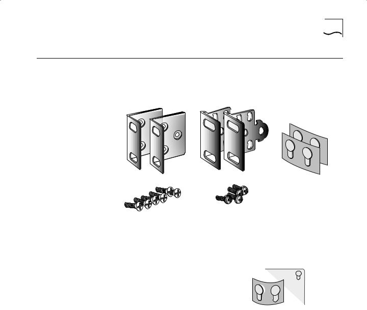
Rack-Mount Kit The rack-mount kit contains the following hardware:
Two rack-mount brackets |
Two stacking brackets |
Six M4x10 mm Phillips flathead |
Four M4x8 mm Phillips |
panhead screws for use |
|
machine screws for use |
with stacking brackets |
with rack-mount brackets |
|
Four adhesive-backed rubber feet
Figure 1-1 Rack-Mount Kit Contents
Installing on a If you plan to install your Tabletop bridge/router on a tabletop, attach
the rubber feet as shown.
Attach feet to corners of chassis bottom
Flex plastic sheet until feet pop loose
1-4 CHAPTER 1: INSTALLING THE HARDWARE
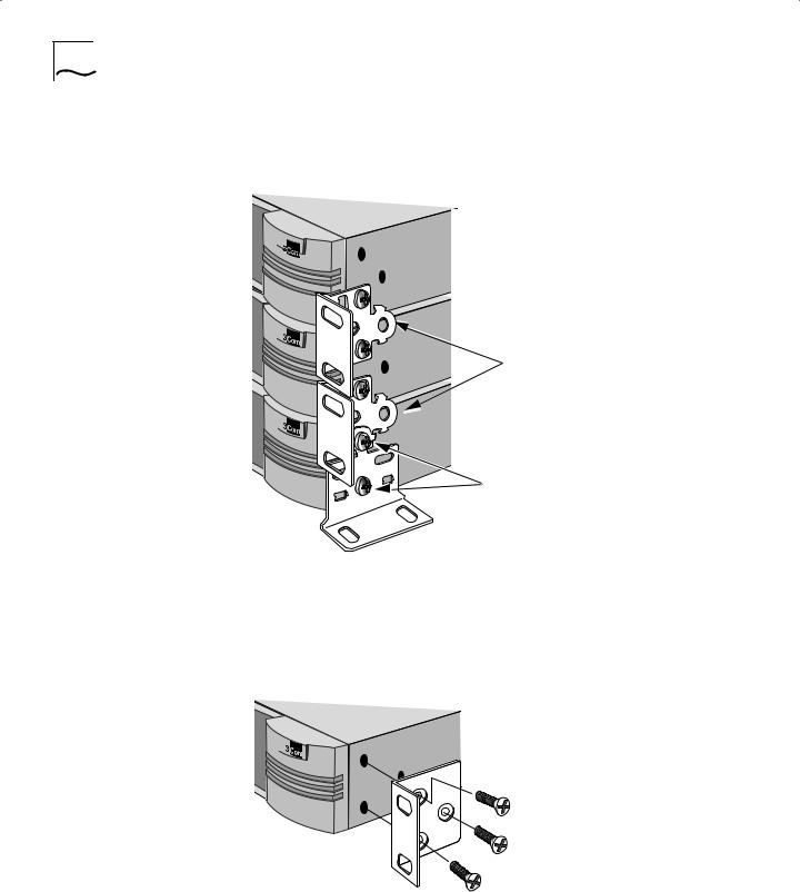
Stacking with The stacking brackets can be used to securely stack several Brackets bridge/routers on a tabletop. Use the stacking brackets and the
M4x8 mm panhead stacking screws shown in Figure 1-1.
Attach brackets as shown to lock two units together
Place screws in holes as shown
Bottom bracket acts as a support
Installing in a Rack To install the bridge/router in a rack, use the rack-mount brackets and the M4x10 mm flathead rack-mount screws shown in Figure 1-1 and follow these steps:
1Secure the rack-mount brackets to each side of the chassis using three flathead screws per bracket.
Cabling the Connectors |
1-5 |
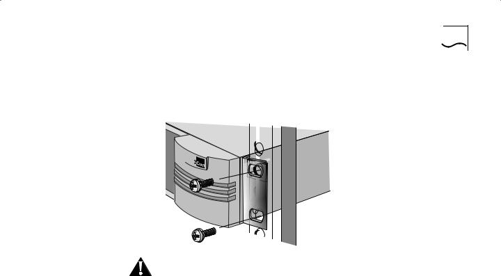
2Hold the chassis between the poles of the rack and attach the brackets to the rack using panhead screws (you must provide these screws). Tighten each screw securely.
|
|
|
|
|
|
|
|
|
|
|
|
|
|
|
|
|
|
|
|
|
CAUTION: Using fewer than two screws to secure the brackets to the |
|||
|
rack may cause the boundary router to fall and sustain damage not |
|||
|
covered by the warranty. |
|||
|
|
|||
Cabling the |
This section describes how to cable the LAN, ISDN, and serial |
|||
Connectors |
connectors on your bridge/router. |
|||
|
If you are planning to connect your SuperStack II bridge/router directly |
|||
|
to another SuperStack II system or to a NETBuilder II® bridge/router |
|||
|
with an HSS V.35 3-port module installed, you must use a modem |
|||
|
eliminator between the two devices. Be sure the default setting of |
|||
|
External for the -PATH CLock parameter is maintained on each device. |
|||
|
Contact your 3Com supplier for a list of suggested modem eliminators. |
|||
1-6 CHAPTER 1: INSTALLING THE HARDWARE
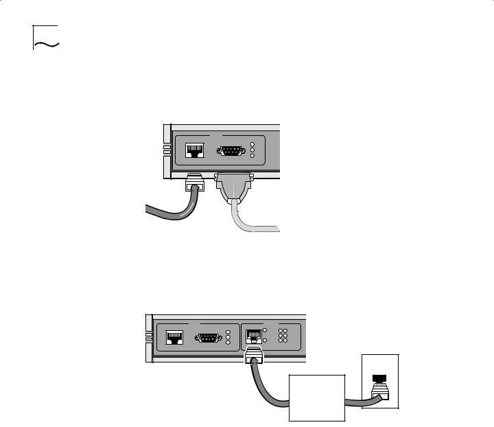
Cabling the LAN
Connector (Models
323, 327, and 52x)
This section applies to models 323, 327, and 52x only. You can use only one type of LAN connector on each bridge/router. The following figure shows how to cable a LAN connector.
|
LAN |
UTP |
STP |
|
16Mb |
|
Active |
|
Fault |
UTP
cable STP OR cable
Cabling the ISDN Connector (Model 52x)
For more information on AUI and 10BASE-T cables, refer to Chapter 2.
This section applies to model 52x bridge/routers only. The following figure shows how to cable an ISDN connector.
|
LAN |
S/T |
ISDN |
B1 B2 |
UTP |
STP |
Line |
Link |
|
|
16Mb |
|
Act |
|
|
|
Connect |
||
|
Active |
|
|
|
|
|
Line |
|
|
|
|
|
Fault |
|
|
Fault |
|
Error |
|
|
|
Wall outlet |
||
|
|
|
|
ISDN cable
Network termination (nt1)/power supply*
*required for U.S. and Canada only
The NT1 and power supply shown in the figure above must either be leased from the telephone company or purchased from an ISDN equipment vendor in the U.S. and Canada only. In other countries, you do not need to provide this equipment because the function of the equipment is provided by the ISDN switch. For more information about ISDN, refer to Appendix A.
For more information on ISDN cables, refer to Chapter 2.

Cabling the Connectors |
1-7 |
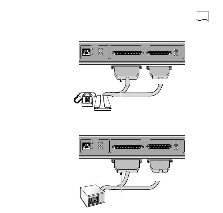
Cabling the Serial
Connectors
The serial connectors provide the following options:
■The UNIVERSAL connector can be converted to a V.35, V.36, X.21, RS-449, or RS-232 connector.
■All serial connectors can function in either DTE or DCE-like mode, which allows you to connect a serial connector to either a CSU/DSU device or modem (DTE mode), or to an IBM cluster controller (DCE-like mode). A connection to an IBM cluster controller must be made using a permanent leased line only. You can operate the serial connectors in any combination of DTE and DCE-like modes.
The cables you use determine the serial connector function. Table 1-2 lists the types of devices available for serial connections, cable options for connection to each device, and if the cable is sold by 3Com. Cables used for IBM cluster controller connectivity (DCE-like mode) are referred to as direct connect cables.
Table 1-2 Serial Connector Cabling Information
|
|
|
Connector |
|
|
Connection to |
Connector* |
Mode |
Cable Name |
Sold by 3Com? |
|
V.35 |
CSU/DSU device or |
V.35 |
DTE |
V.35 to V.35 DCE cable |
No. Easily obtained from |
modem |
|
|
|
cable manufacturer. |
|
|
|
|
|
|
|
V.35 |
CSU/DSU device or |
UNIVERSAL |
DTE |
V.35 adapter cable |
Yes (3C8035). |
modem |
|
|
|
|
|
|
|
|
|
|
|
V.35 |
IBM cluster controller |
V.35 |
DCE-like |
V.35 to V.35 direct connect |
No. See Chapter 2 for |
|
|
|
|
cable |
pin assignments. |
|
|
|
|
|
|
V.35 |
IBM cluster controller |
UNIVERSAL |
DCE-like |
UNIVERSAL to V.35 direct |
Yes (3C8135). |
|
|
|
|
connect cable |
|
|
|
|
|
|
|
X.21 |
CSU/DSU device or |
UNIVERSAL |
DTE |
X.21 adapter cable |
Yes (3C8021). |
modem |
|
|
|
|
|
|
|
|
|
|
|
RS-449 or V.36 CSU/DSU |
UNIVERSAL |
DTE |
UNIVERSAL to RS-449/V.36 |
No. See Chapter 2 for |
|
device or modem |
|
|
DCE cable |
pin assignments. |
|
|
|
|
|
|
|
RS-449 or V.36 IBM cluster |
UNIVERSAL |
DCE-like |
UNIVERSAL to RS-449/V.36 |
No. See Chapter 2 for |
|
controller |
|
|
direct connect cable |
pin assignments. |
|
|
|
|
|
|
|
RS-232 CSU/DSU device or |
UNIVERSAL |
DTE |
UNIVERSAL to RS-232 DCE |
Yes (3C8023). |
|
modem |
|
|
cable |
|
|
|
|
|
|
|
|
RS-232 CSU/DSU device or |
RS-232 |
DTE |
RS-232 to RS-232 DCE cable |
No. Easily obtained from |
|
modem |
|
|
|
cable manufacturer. |
|
|
|
|
|
|
|
RS-232 IBM cluster controller |
UNIVERSAL |
DCE-like |
UNIVERSAL to RS-232 direct |
Yes (3C8123). |
|
|
|
|
|
connect cable |
|
|
|
|
|
|
|
RS-232 IBM cluster controller |
RS-232 |
DCE-like |
RS-232 to RS-232 direct |
Yes (3C8132). |
|
|
|
|
|
connect cable |
|
*If you cable the UNIVERSAL connector, you need to perform some software configuration. For more information, refer to the software guide.

1-8 CHAPTER 1: INSTALLING THE HARDWARE
The following figures show how to cable the serial connectors.
Models 32x (DTE mode)
V.35 (A) |
SERIAL |
|
SuperStack II |
|
|
A B C |
NETBuilder |
|
|
UNIVERSAL (B) |
RS-232 (C) |
Link |
Console |
Run |
|
|
Active |
||
|
|
Status |
Load |
|
|
|
|
||
|
|
Fault |
|
|
|
|
|
Test |
Fwd Power
SYSTEM /Fault
RS-232 DCE cable
V.35 DCE cable
V.35 adapter
X.21 adapter RS-449/V.36 DCE
or RS-232 DCE cables
Models 32x (DCE-like mode)
|
SERIAL |
|
SuperStack II |
|
V.35 (A) |
RS-232 (C) |
B C |
NETBuilder |
|
UNIVERSAL (B) |
Link |
Console |
Run |
|
|
|
Active |
||
|
|
Status |
Load |
|
|
|
|
||
|
|
Fault |
|
|
|
|
|
Test |
Fwd Power
SYSTEM /Fault
V.35 direct connect cable
RS-232 direct |
IBM cluster |
|
connect cable |
||
controller |
||
|
V.35 direct connect RS-449/V.36 direct connect
or RS-232 direct connect cables
Cabling the Connectors |
1-9 |
Models 52x (DTE mode)
S/T |
ISDN |
B1 B2 |
|
|
SERIAL |
|
Line |
|
Link |
|
B |
C |
|
|
Act |
|
UNIVERSAL (B) |
RS-232 (C) |
Link |
|
|
|
|
||||
|
|
|
Connect |
|
|
Active |
|
Line |
|
|
|
|
|
|
|
Fault |
|
|
Fault |
|
|
Error |
|
|
|
||
|
|
|
|
|
RS-232 DCE cable
V.35 adapter
X.21 adapter RS-449/V.36 DCE
or RS-232 DCE cables
Models 52x (DCE-like mode)
S/T |
ISDN |
B1 B2 |
|
|
SERIAL |
|
Line |
|
Link |
|
B |
C |
|
|
Act |
|
UNIVERSAL (B) |
RS-232 (C) |
Link |
|
|
|
|
||||
|
|
|
Connect |
|
|
Active |
|
Line |
|
|
|
|
|
|
|
Fault |
|
|
Fault |
|
|
Error |
|
|
|
||
|
|
|
|
|
IBM cluster |
RS-232 direct |
|
connect cable |
||
controller |
||
|
V.35 direct connect RS-449/V.36 direct connect
or RS-232 direct connect cables
1-10 CHAPTER 1: INSTALLING THE HARDWARE
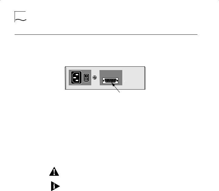
Attaching a |
You can attach your SuperStack II bridge/router to a SuperStack II |
|||
Redundant Power |
Redundant Power System (RPS). You will need to order the connecting |
|||
System |
cable (part number 3C8101) from 3Com. The following figure shows |
|||
|
where to attach this cable. |
|||
|
Rear panel of unit |
|
|
|
|
|
|||
|
|
|
|
|
|
|
|
|
|
|
|
|
|
|
Attach RPS cable here
For full power supply redundancy, attach one end of the RPS cable to the rear panel on the bridge/router and the other end to the RPS. Then attach one end of the power cord to the rear panel on the bridge/router and the other end to a power outlet.
In this configuration, the internal supply provides power. If the internal supply fails or is switched off, or if there is a power failure, the RPS is activated and the bridge/router reboots.
To reset a bridge/router in this configuration, turn the power off, wait 5 seconds and turn it back on. The bridge/router switches to the RPS, then switches back to the internal supply to reboot.
CAUTION: For system susceptibility protection, always leave the AC cord attached to the bridge/router hardware and to a power outlet.
Internal power supply failure is rare. If it occurs, the power switch on your bridge/router will not operate. To reboot you will need to unplug the RPS cable and then plug it back in. Replace your bridge/router with another bridge/router that has a functioning internal power supply as soon as possible. Contact your 3Com representative to replace your bridge/router.
Connecting a PC, Terminal, or Modem 1-11
Connecting a PC, |
Connect a PC running a terminal emulation program, a terminal, or a |
Terminal, or |
modem to the Console port on the SuperStack II bridge/router to |
Modem |
configure the bridge/router software and review startup and system |
|
operation messages. |
|
To connect a PC, terminal, or modem to the DPE module, follow these |
|
steps: |
1Obtain a cable to connect the console to the Console port on the bridge/router. See “Console Cables” on page 2-3 for cable pinouts.
The Console port is a 9-pin male connector.
For the PC, use a 9-pin female to 9-pin female PC cable. A null modem-type cable may be used.
For the terminal, use a 9-pin female to 25-pin terminal cable. A null modem-type cable may be used.
For the modem, use a 9-pin female to 25-pin male modem cable. A straight-through-type cable may be used.
2Connect one end of the cable to the Console port on the SuperStack II system and the other end to the serial port on the back of your console.
3Verify that configurable parameters of your console match the configuration settings of the Console port specified in Table 1-3.
Table 1-3 CONSOLE Port Configuration Settings
Characteristic |
Setting |
|
|
Baud rate |
9600 |
Databits |
8 |
Parity |
None |
Stop bits |
1 |
DTR |
Ignored |
Duplex |
Full |
Echo |
Off |
Flow control |
X-on/X-off |
|
|
4 Turn on the console.

1-12 CHAPTER 1: INSTALLING THE HARDWARE
Shutting Down If your SuperStack II system is not connected to an RPS, turn off the power by pressing the off (0) side of the power switch on the back panel. If your system is connected to an RPS, turn off the power by unplugging the RPS cable from the system and then pressing the off (0) side of the power switch.

OVERVIEW
2
This chapter provides an overview of the SuperStack II NETBuilder bridge/router, including information on:
■Model features
■Chassis panels
■LEDs
■DIP switches
■Hardware interrupt switch
■Connectors and cables
■Physical specifications
Model Features |
|
Table 2-1 lists each SuperStack II NETBuilder model along with |
||||||
|
|
|
memory, port, and upgrade information. |
|
|
|||
Table 2-1 SuperStack II NETBuilder Model Features |
|
|
|
|||||
|
|
|
|
|
|
|
|
|
|
Flash |
|
|
Active WAN |
Flash Memory |
DRAM |
Software |
|
Model |
Memory |
DRAM |
LAN Ports |
Ports |
Upgradeable To |
Upgradeable To |
Upgradeable |
|
|
|
|
|
|
|
|
|
|
320 |
4 MB |
8 MB |
None |
3 serial |
8 MB |
12 MB |
Yes |
|
|
|
|
|
|
|
|
|
|
323 |
4 MB |
8 MB |
1 UTP or |
1 serial |
8 MB |
12 MB |
Yes |
|
|
|
|
STP |
1 |
backup serial |
|
|
|
|
|
|
|
|
|
|
||
|
|
|
|
|
|
|
|
|
327 |
4 MB |
8 MB |
1 UTP or |
3 serial |
8 MB |
12 MB |
No |
|
|
|
|
STP |
|
|
|
|
|
|
|
|
|
|
|
|
|
|
523 |
4 MB |
8 MB |
1 UTP or |
1 |
ISDN BRI |
8 MB |
12 MB |
Yes |
|
|
|
STP |
1 |
serial |
|
|
|
|
|
|
|
|
|
|
||
|
|
|
|
|
|
|
|
|
527 |
4 MB |
8 MB |
1 UTP or |
1 |
ISDN BRI |
8 MB |
12 MB |
No |
|
|
|
STP |
2 |
serial |
|
|
|
|
|
|
|
|
|
|
||
|
|
|
|
|
|
|
|
|
Chassis Panels |
The following figures show the front and back panels for each chassis. |
Loading...