


 Loading...
|
SuperStack® II Switch 3000 TX 8 Port |
® |
User Guide |
Agent Software Version 3.1
http://www.3com.com/
Document No. DUA1694-1AAA04
Published June 1997
3Com Corporation ■ 5400 Bayfront Plaza ■ Santa Clara, California ■ 95052-8145
Copyright © 3Com Ireland, 1997. All rights reserved. No part of this documentation may be reproduced in any form or by any means or used to make any derivative work (such as translation, transformation, or adaptation) without permission from 3Com Ireland.
3Com Ireland reserves the right to revise this documentation and to make changes in content from time to time without obligation on the part of 3Com Ireland to provide notification of such revision or change.
3Com Ireland provides this documentation without warranty of any kind, either implied or expressed, including, but not limited to, the implied warranties of merchantability and fitness for a particular purpose. 3Com may make improvements or changes in the product(s) and/or the program(s) described in this documentation at any time.
UNITED STATES GOVERNMENT LEGENDS:
If you are a United States government agency, then this documentation and the software described herein are provided to you subject to the following restricted rights:
For units of the Department of Defense:
Restricted Rights Legend: Use, duplication, or disclosure by the Government is subject to restrictions as set forth in subparagraph (c) (1) (ii) for Restricted Rights in Technical Data and Computer Software Clause at 48 C.F.R. 52.227-7013. 3Com Ireland, c/o 3Com Limited, 3Com Centre, Boundary Way, Hemel Hempstead, Herts, HP2 7YU, United Kingdom.
For civilian agencies:
Restricted Rights Legend: Use, reproduction, or disclosure is subject to restrictions set forth in subparagraph (a) through (d) of the Commercial Computer Software - Restricted Rights Clause at 48 C.F.R. 52.227-19 and the limitations set forth in 3Com Corporation’s standard commercial agreement for the software. Unpublished rights reserved under the copyright laws of the United States.
If there is any software on removable media described in this documentation, it is furnished under a license agreement included with the product as a separate document, in the hard copy documentation, or on the removable media in a directory file named LICENSE.TXT. If you are unable to locate a copy, please contact 3Com and a copy will be provided to you.
Unless otherwise indicated, 3Com registered trademarks are registered in the United States and may or may not be registered in other countries.
3Com, NetAge, SuperStack, and Transcend are registered trademarks of 3Com Corporation. 3ComFacts is a service mark of 3Com Corporation.
Other brand and product names may be registered trademarks or trademarks of their respective holders.
Environmental Statement
It is 3Com’s policy to be environmentally friendly in all its operations. This manual is printed on paper that comes from European sustainable, managed forests. The production process for making the pulp has a reduced AOX level (adsorbable organic halogen) resulting in elemental chlorine free paper.
The paper is fully biodegradable and recyclable.

CONTENTS
ABOUT THIS GUIDE
Introduction 1
How to Use This Guide 1
Conventions 2
Related Documentation 2
1 GETTING STARTED
About the Switch 3000 TX 1-1
Summary of Features 1-1
Port Connections 1-2
100BASE-TX Ports 1-2
Plug-in Module 1-2
Switch Operation and Features 1-2
Intelligent Flow Management 1-2
Full Duplex 1-2
Resilient Links 1-2
Virtual LANs (VLANs) 1-3
Spanning Tree Protocol 1-3
PACE 1-3
Network Configuration Examples 1-4
Unit Overview — Front 1-6
100BASE-TX Ports 1-7
LEDs 1-7
Unit Overview — Rear 1-8
Power Socket 1-9
Unit Serial Number 1-9
Redundant Power System Socket 1-9
Reset Button 1-9
Console Port 1-9
Plug-in Module Slot 1-9
Ethernet Address 1-9
Unit Defaults 1-10
Managing the Switch 3000 TX 1-10
Quick Start For SNMP Users 1-11
Entering an IP Address for the Switch 1-11
2 INSTALLATION AND SETUP
Following Safety Information 2-1 Positioning the Switch 3000 TX 2-1 Configuration Rules for Fast Ethernet 2-2 Configuration Rules with Full Duplex 2-2 Installing the Switch 3000 TX 2-4
Rack Mounting 2-4
Stacking the Switch and Other Units 2-4 Wall Mounting 2-5
Powering-Up the Switch 2-6
Connecting a Redundant Power System (RPS) 2-6 Connecting Equipment to the Console Port 2-7
Connecting a VT100 Terminal 2-7 Connecting a VT100 Terminal Emulator 2-7 Connecting a Workstation Running SLIP 2-8

3 SETTING UP FOR MANAGEMENT
Methods of Managing the Switch 3000 TX 3-1 Using the VT100 Management Interface 3-1 Using Telnet 3-2
Managing Over The Network 3-2 IP Addresses 3-2
Obtaining a Registered IP Address 3-3 Navigating the VT100 Screens 3-4
Screen Conventions 3-4
Keyboard Shortcuts 3-5
Correcting Text Entry 3-5
Setting up the Switch for Management 3-6 Logging On 3-6
After Logging On 3-8
Switch Management Setup 3-9 Logging Off 3-12
Auto Logout 3-12
4 MANAGING THE SWITCH 3000 TX
Setting Up Users 4-2
Creating a New User 4-3
Deleting a User 4-4
Editing User Details 4-5
Assigning Local Security 4-6
Choosing a Switch Management Level 4-7
Setting Up the Switch Unit 4-9
Setting Up the Switch Ports 4-11
Setting Up the Switch Database (SDB) 4-15
The Database View 4-16
Searching the Switch Database 4-17
By MAC Address 4-17
By Port 4-17
Adding an Entry into the SDB 4-17
Deleting an Entry from the SDB 4-17
Specifying that an Entry is Permanent 4-17
Setting Up Resilient Links 4-18
Configuring Resilient Links 4-19
Creating a Resilient Link Pair 4-20
Deleting a Resilient Link Pair 4-20
Viewing the Resilient Links Setup 4-21
Setting Up Traps 4-23
Setting up the Console Port 4-24
Resetting the Switch 3000 TX 4-26
Initializing the Switch 3000 TX 4-27
Upgrading Software 4-28
5 ADVANCED MANAGEMENT
Virtual LANs (VLANs) 5-1 What are VLANs? 5-1 Benefits of VLANs 5-1
How VLANs Ease Change and Movement 5-2 How VLANs Control Broadcast Traffic 5-2 How VLANs Provide Extra Security 5-2
An Example 5-2
VLANs and the Switch 3000 TX 5-3
The Default VLAN and Moving Ports From the Default VLAN 5-3
Connecting VLANs to a Router 5-3
Connecting Common VLANs Between Switch Units 5-3
Using AutoSelect VLAN Mode 5-4
Using Non-routable Protocols 5-5
Using Unique MAC Addresses 5-5 Extending VLANs into an ATM Network 5-5
VLAN Configuration Example 5-6

Setting Up VLANs on the Switch 5-8
Assigning a Port to a VLAN When Using Port VLAN Mode 5-9
Specifying that a Port is a VLT port 5-9
Setting Up VLANs Using AutoSelect VLAN Mode 5-10 Specifying Information About the VLAN Server 5-10 Specifying AutoSelect VLAN Mode 5-11
Spanning Tree Protocol 5-12 What is STP? 5-12
How STP Works 5-14 STP Initialization 5-14 STP Stabilization 5-14
STP Reconfiguration 5-14 An Example 5-15
STP Configurations 5-16 Enabling STP on the Switch 5-17
Configuring STP on the Switch 5-18
Configuring the STP Parameters of VLANs 5-18 Configuring the STP Parameters of Ports 5-20
RMON 5-22
What is RMON? 5-22
About the RMON Groups 5-22 Statistics 5-22
History 5-22
Alarms 5-22
Hosts 5-23 Hosts Top N 5-23 Matrix 5-23 Filter 5-23 Capture 5-23 Events 5-23
Benefits of RMON 5-24 RMON and the Switch 5-24
RMON Features of the Switch 5-25
About Alarm Actions 5-26
About Default Alarm Settings 5-27
About the Audit Log 5-27
6 STATUS MONITORING AND STATISTICS
Summary Statistics 6-2
Port Statistics 6-3
Port Traffic Statistics 6-4
Port Error Analysis 6-6
Status Monitoring 6-8
Fault Log 6-9
Remote Polling 6-10
A SAFETY INFORMATION
Important Safety Information A-1
Power Supply and Fuse A-3
Sockets for Redundant Power System (RPS) A-3 RJ45 Ports A-3
L’information de Sécurité Importante A-4 La Source de Courant et Le Fusible A-5 Socle Pour Alimentation Multiple A-6 Les Ports RJ45 A-6
Wichtige Sicherheitsinformationen A-7 Stromversorgung und Sicherung A-8 Steckdose für Redundant Power System A-8 RJ45 Anschlußen A-8
B SCREEN ACCESS RIGHTS

C TROUBLE-SHOOTING
LEDs C-1
Using the VT100 Interface C-2
Using the Switch C-3
D PIN-OUTS
Null Modem Cable D-1
PC-AT Serial Cable D-1
Modem Cable D-2
RJ45 Pin Assignments D-2
ESWITCH 3000 TX TECHNICAL SPECIFICATIONS
FTECHNICAL SUPPORT
Online Technical Services F-1 World Wide Web Site F-1
3Com Bulletin Board Service F-1 Access by Analog Modem F-1 Access by Digital Modem F-2
3ComFacts Automated Fax Service F-2 3ComForum on CompuServe Online Service F-2
Support from Your Network Supplier F-3 Support from 3Com F-3
Returning Products for Repair F-4
GLOSSARY
3COM CORPORATION LIMITED WARRANTY
ELECTRO-MAGNETIC COMPATIBILITY STATEMENTS
INDEX
ABOUT THIS GUIDE
About This Guide provides an overview of this guide, describes the guide conventions, tells you where to look for specific information and lists other publications that may be useful.
Introduction
This guide provides the information you need to install and configure the Switch 3000 TX 8 Port (3C16941A) with v3.1 agent software.
This guide is intended for use by network administrators who are responsible for installing and setting up network equipment. It assumes a basic working knowledge of Local Area Networks.
If the information in the Release Notes shipped with your product differs from the information in this guide, follow the Release Notes.
Throughout this guide, the SuperStack® II
Switch 3000 TX 8 Port is referred to as the
Switch 3000 TX, or Switch.
How to Use This Guide
This table shows where to find specific information in this guide.
If you are looking for... |
Turn to... |
|
|
An overview of the Switch |
Chapter 1 |
Information about installing the Switch into your net- |
Chapter 2 |
work |
|
Information about the methods you can use to |
Chapter 3 |
manage the Switch |
|
Information about managing the Switch |
Chapter 4 |
Information about more advanced management |
Chapter 5 |
features; for example VLANs, Spanning Tree and |
|
RMON |
|
Information about monitoring the status of the Switch |
Chapter 6 |
Safety information |
Appendix A |
Information about the access rights for each VT100 |
Appendix B |
screen |
|
Trouble-shooting information |
Appendix C |
Information about the pin-outs relating to the Switch |
Appendix D |
Information about the Technical Specifications of the |
Appendix E |
Switch |
|
Information about the Technical Support available |
Appendix F |
from 3Com |
|
|
|
2 ABOUT THIS GUIDE
Conventions
Table 1 and Table 2 list conventions that are used throughout this guide.
Table 1 Text Conventions
Convention |
Description |
|
Screen |
This typeface represents information as it |
|
displays |
appears on the screen. |
|
The words |
When you see the word “enter” in this guide, |
|
“enter” |
you must type something, and then press the |
|
and “type” |
Return or Enter key. Do not press the Return or |
|
|
Enter key when an instruction simply says |
|
|
“type.” |
|
[Key] names |
Key names appear in text in one of two ways: |
|
|
■ |
Referred to by their labels, such as “the |
|
|
Return key” or “the Escape key” |
|
■ |
Written with brackets, such as [Return] or |
|
|
[Esc]. |
|
If you must press two or more keys simulta- |
|
|
neously, the key names are linked with a plus |
|
|
sign (+). Example: |
|
|
|
Press [Ctrl]+[Alt]+[Del]. |
Menu commands |
Menu commands or button names appear in |
|
and buttons |
italics. Example: |
|
|
|
From the Help menu, select Contents. |
Words in italicized |
Italics emphasize a point or denote new terms at |
|
type |
the place where they are defined in the text. |
|
Words in |
Bold text denotes key features. |
|
bold-face type |
|
|
Table 2 |
Notice Icons |
|
Icon |
Notice Type |
Alerts you to... |
|
Information |
Important features or instructions |
|
note |
|
|
Caution |
Risk of personal injury, system damage, |
|
|
or loss of data |
|
Warning |
Risk of severe personal injury |
Related Documentation
The Switch 3000 TX document set includes:
■SuperStack II Switch 3000 TX 8 Port Quick Reference Guide.
Document Number DQA1694-1AAA0x
■SuperStack II Switch 3000 TX 8 Port Quick Installation Guide.
Document Number DIA1694-1AAA0x
■SuperStack II Switch 3000 TX 8 Port Release Notes.
Document Number DNA1694-1AAA0x
Other publications you may find useful:
■Documentation accompanying the Plug-in Modules.
■Documentation accompanying the Redundant Power System.
1 GETTING STARTED
About the Switch 3000 TX
Switching is currently a leading option for increasing performance by providing high speed backbone links and eliminating server bottlenecks. Part of the 3Com SuperStack® II range of products, the Switch 3000 TX provides simple, low cost and high performance switched connections to Fast Ethernet networks.
The SuperStack II Switch 3000 TX is a revision of the LinkSwitch 3000 TP.
Summary of Features
The Switch 3000 TX has the following features:
■Eight 100BASE-TX ports
■Plug-in Module slot (Asynchronous Transfer Mode (ATM) and Fast Ethernet)
■Support for up to 4080 addresses in the Switch Database
■Store-and-forward forwarding mode ensuring the switch forwards all valid Ethernet frames and discards invalid Ethernet frames such as those with an incorrect CRC
■Intelligent Flow Management for congestion control
■Full Duplex on all fixed ports, and Fast Ethernet Plug-in Module ports
■Resilient Links
■Support for 16 Virtual LANs (VLANs)
■Spanning Tree Protocol (STP) per VLAN
■PACE (Priority Access Control Enabled) for supporting multimedia applications over Ethernet
■3Com’s SuperStack II architecture:
■Connects to Redundant Power System
■Integrated network management
■19-inch rack or stand-alone mounting
■SmartAgent support:
■IP and IPX management over SNMP
■RMON
■Repeater and Bridge MIB
■Broadcast storm control
■Easy software upgrades
■BOOTP for automatic IP address configuration
■Local management
1-2 CHAPTER 1: GETTING STARTED
Port Connections
100BASE-TX Ports
The Switch has eight Fast Ethernet 100BASE-TX ports configured as MDIX (cross-over), which provide a 100Mbps connection to other Fast Ethernet devices such as the SuperStack II Switch 1000. The maximum segment length is 100m (328ft) over category 5 twisted pair cable.
As these ports are configured as MDIX (cross-over), you need to use a cross-over cable to connect to devices whose ports are MDIX-only. Most 100BASE-TX ports in 3Com devices are MDIX-only.
Plug-in Module
A slot at the rear of the unit can take a Plug-in Module, providing an additional high-speed port if required. This could be used to provide a Fast Ethernet or Asynchronous Transfer Mode (ATM) backbone connection to the rest of your network.
Switch Operation and Features
The Switch 3000 TX uses the same algorithm as a conventional 802.1d bridge for filtering, forwarding and learning packet addresses.
Intelligent Flow Management
Intelligent Flow Management (IFM) is a system for controlling congestion on your network. Congestion can be caused by one or more devices sending traffic to an already busy port on the Switch. If a port on the Switch is connected to another switch or endstation, IFM prevents packet loss and inhibits
the device from generating more packets until the period of congestion ends.
IFM should be enabled on a port if it is connected to another switch, or an endstation. IFM should be disabled on a port connected to a repeater.
For more information about enabling IFM, refer to “Setting Up the Switch Ports” on page 4-11.
Full Duplex
The Switch 3000 TX provides full duplex support for all its fixed ports, and Fast Ethernet Plug-in Module ports. Full duplex allows frames to be transmitted and received simultaneously and, in effect, doubles the potential throughput of a link. In addition, full duplex also supports 100BASE-FX cable runs of up to 2km (6562ft).
Full Duplex can be enabled on all ports, or on individual ports. For more information, refer to “Setting Up the Switch Unit” and “Setting Up the Switch Ports” in Chapter 4.
Resilient Links
The Switch’s Resilient Link feature enables you to protect critical links and prevent network downtime should those links fail. Setting up resilience ensures that should a main communication link fail, a standby duplicate link immediately and automatically takes over the task of the main link. Each main and standby link pair is referred to as a resilient link pair.
For more information about resilient links, refer to “Setting Up Resilient Links” on page 4-18.
Virtual LANs (VLANs)
The Switch 3000 TX has a Virtual LAN (VLAN) feature which allows you to build your network segments without being restricted by physical connections. A VLAN is defined as a group of locationand topology-independent devices that communicate as if they are on the same physical LAN.
Implementing VLANs on your network has three main advantages:
■It eases the change and movement of devices on IP networks. If an endstation in VLAN 1 is moved to a port in another part of the network, you only need to specify that the new port is in VLAN 1.
■It helps to control broadcast traffic. If an endstation in VLAN 1 transmits a broadcast frame, then only VLAN 1 devices receive the frame.
■It provides extra security. Devices in VLAN 1 can only communicate with devices in VLAN 2 using a router.
For more information about VLANs, refer to “Virtual LANs (VLANs)” on page 5-1.
Spanning Tree Protocol
The Switch 3000 TX supports the Spanning Tree Protocol (STP) which is a bridge-based system for providing fault tolerance on networks. STP allows you to implement parallel paths for network traffic, and ensure that:
■Redundant paths are disabled when the main paths are operational
About the Switch 3000 TX |
1-3 |
■Redundant paths are enabled if the main traffic paths fail
For more information about STP, refer to “Spanning Tree Protocol” on page 5-12.
PACE
The Switch 3000 TX supports PACE (Priority Access Control Enabled) technology, which allows multimedia traffic to be carried over standard Ethernet and Fast Ethernet LANs. PACE provides two features:
■Implicit Class of Service — When multimedia traffic is transmitted, it is given a higher priority than other data and is therefore forwarded ahead of other data when it arrives at the Switch. The Implicit Class of Service feature minimizes latency through the Switch and protects the quality of multimedia traffic.
■Interactive Access — When two-way multimedia traffic passes over an Ethernet network, interference can occur because access to the bandwidth is unequally allocated to traffic in one direction.
The Interactive Access feature allocates the available bandwidth equally in both directions, therefore increasing the quality of the traffic.
For more information about setting up PACE on the Switch, refer to “Setting Up the Switch Unit” and “Setting Up the Switch Ports” in Chapter 4.
1-4 CHAPTER 1: GETTING STARTED
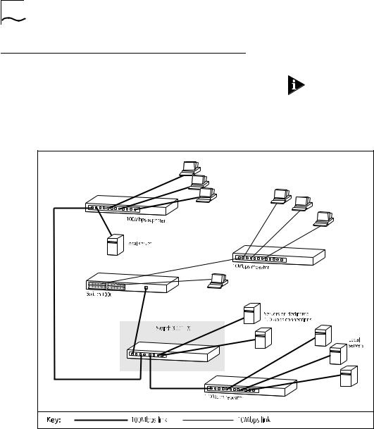
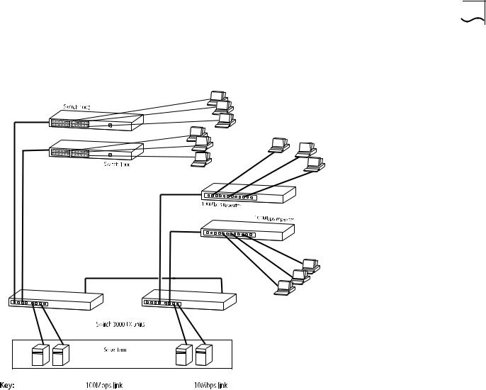
Network Configuration Examples
The following two illustrations show some examples of how the Switch 3000 TX can be used on your network.
Examples of how the Switch 3000 TX can be used in a VLAN-based network are given in Chapter 5.
Figure 1-1 |
The Switch 3000 TX used as a data-center switch |
|
|
|
|
|
|
Network Configuration Examples |
1-5 |
|
|
|
|
|
|
|
|
|
|
|
|
|
|
|
|
|
|
|
|
|
|
|
|
|
|
|
|
|
|
|
|
|
|
|
|
|
|
|
|
|
|
|
|
|
|
|
|
|
|
|
|
|
|
|
Figure 1-2 Increasing port density with the Switch 3000 TX
1-6 CHAPTER 1: GETTING STARTED
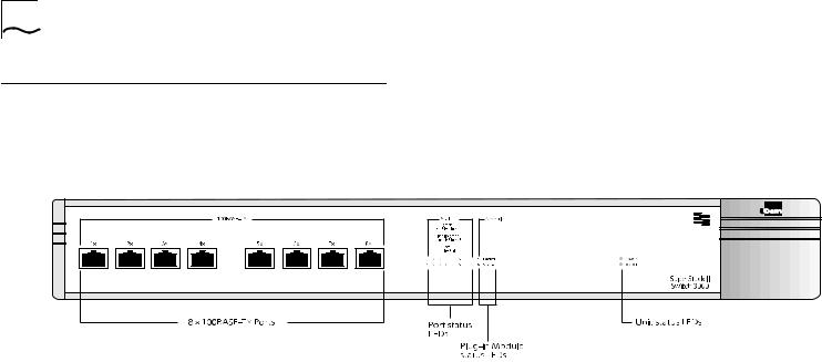
Unit Overview — Front
Figure 1-3 Switch 3000 TX front view

100BASE-TX Ports
The Switch 3000 TX has eight Fast Ethernet 100BASE-TX RJ45 ports configured as MDIX (cross-over), which provide connection to other Fast Ethernet devices such as the SuperStack II Switch 1000. The maximum segment length is 100m (328ft) over category 5 UTP or STP cable.
As these ports are configured as MDIX (cross-over), you need to use a cross-over cable to connect to devices whose ports are MDIX-only. Most of the 100BASE-TX ports in 3Com devices are MDIX-only.
LEDs
Table 1-1 describes the LED behavior on the Switch 3000 TX. For more details about corrective action in the event of a problem, refer to “LEDs” on page C-1.
|
|
Unit Overview — Front |
1-7 |
Table 1-1 LED behavior |
|
|
|
|
|
||
|
|
|
|
LED |
Color |
Indicates |
|
|
|
||
Port Status LEDs (ports 1 – 8) |
|
||
Packet |
Yellow |
Frames are being transmitted/received |
|
|
|
on the port. |
|
Status |
Green |
Link is present; port is enabled. |
|
|
Green flashing |
Link is present; port is disabled. |
|
|
Off |
Link is not present. |
|
Plug-in Module Status LEDs (port 9) |
|
||
Packet |
Yellow |
Frames are being transmitted/received |
|
|
|
on the Plug-in Module port. |
|
Status |
Green |
Link is present; port is enabled. |
|
|
Green flashing |
Link is present; port is disabled. |
|
|
Green flashing |
Refer to the “SuperStack II Switch ATM |
|
|
(long on, short off) OC-3c Module User Guide”. |
|
|
|
Yellow |
Plug-in Module has failed its Power On |
|
|
|
Self Test (if the MGMT LED is flashing |
|
|
|
yellow), or the agent software of the |
|
|
|
Plug-in Module is not installed correctly. |
|
|
Yellow flashing |
Plug-in Module is not recognized. |
|
|
Off |
Link is not present or the Plug-in Mod- |
|
|
|
ule is not installed in the Switch. |
|
Unit Status LEDs |
|
|
|
Power |
Green |
Switch is powered-up. |
|
MGMT |
Green |
Switch is operating normally. |
|
|
Green flashing |
Switch or Plug-in Module is either |
|
|
|
downloading software or initializing |
|
|
|
(which includes a Power On Self Test). |
|
|
Yellow |
Switch has failed its Power On Self Test. |
|
|
Yellow flashing |
Plug-in Module has failed its Power On |
|
|
|
Self Test. |
|
|
|
|
|
1-8 CHAPTER 1: GETTING STARTED
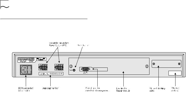
Unit Overview — Rear
Figure 1-4 Switch 3000 TX rear view

Power Socket
The Switch 3000 TX automatically adjusts to the supply voltage. The fuse is suitable for both 110V A.C. and 220–240V A.C. operation. For information on replacing fuses, refer to Appendix A.
Unit Serial Number
You may need this serial number for fault reporting purposes.
Redundant Power System Socket
Use one of these sockets to connect a SuperStack II Redundant Power System (RPS) to the unit. You can use either socket. Refer to “Connecting a Redundant Power System (RPS)” on page 2-6.
Reset Button
Press the reset button to simulate a power-off/on cycle. This has the same effect as carrying out a reset via the VT100 interface; refer to “Resetting the Switch 3000 TX” on page 4-26.
Console Port
Connect a terminal to the console port to carry out remote or local out-of-band configuration and management. Configuration for the console port is set to auto-baud, 8 data bits, no parity, and 1 stop bit.
Unit Overview — Rear |
1-9 |
Plug-in Module Slot
Use this slot to install a Plug-in Module. The Module can be used to provide an additional high speed link to the rest of your network. 3Com provides a range of Plug-in Modules; contact your supplier for availability.
When no Plug-in Module is installed, the blanking plate should be secured in place.
Ethernet Address
This label shows the unique Ethernet (or MAC) address assigned to the unit.

1-10 CHAPTER 1: GETTING STARTED
Unit Defaults
The following table shows the factory defaults for the Switch 3000 TX features.
Port Status |
Enabled |
Intelligent Flow |
Enabled |
Management |
|
Duplex Mode |
Half duplex on all relevant ports |
Virtual LANs |
All ports use Port VLAN Mode and |
|
belong to the Default VLAN (VLAN 1) |
PACE |
Disabled |
Spanning Tree |
Disabled |
(STP) |
|
Power On Self Test |
Normal (Fast Boot) |
(POST) |
|
System Alarm (broadcast bandwidth used)
System Alarm (errors per 10,000 packets)
System Alarm
(bandwidth used)
Enabled
■High threshold: 20% — Notify and Blip
■Low threshold: 10% — No action
Enabled
■High threshold: 2% — Notify
■Low threshold: 1% — No action
Enabled
■High threshold: 85% — No action
■Low threshold: 50% — No action
System Alarm |
Enabled |
|
(percentage of |
■ |
High threshold: 85% — No action |
frames forwarded) |
■ |
Low threshold: 50% — No action |
|
||
Managing the Switch 3000 TX
The menu-driven interface built into the Switch 3000 TX is known as the VT100 interface. You can access it using a VT100 terminal, or a PC using terminal emulation software. You can connect the terminal directly to the Switch or via a modem. You can also access the VT100 interface remotely using Telnet running over the TCP/IP protocol.
Remote management is also possible using a Network Manager from 3Com’s Transcend® product range. The management protocol is SNMP (Simple Network Management Protocol) and any SNMP-based management facility can manage the unit if the Management Information Base (MIB) is installed correctly in the management workstation. The Switch 3000 TX supports SNMP over both IP and IPX protocols.
Quick Start For SNMP Users
This section describes how to get started if you want to use an SNMP Network Manager to manage the Switch. It assumes you are already familiar with SNMP management.
■If you are using IP and you have a BOOTP server set up correctly on your network, the IP address for the Switch is detected automatically and you can start managing the Switch without any further configuration.
■If you are using the IPX protocol, the Switch 3000 TX is allocated an IPX address automatically. You can start the SNMP Network Manager and begin managing the Switch.
■If you are using IP without a BOOTP server, you must enter the IP address of the Switch before the SNMP Network Manager can communicate with the device. To do this, refer to “Entering an IP Address for the Switch”, below.
If you need more information about IP and IPX, refer to “Managing Over The Network” on page 3-2.
Entering an IP Address for the Switch
1Connect a terminal to the console port of the Switch 3000 TX. The terminal should be configured to 9600 line speed (baud rate), 8 data bits, no parity, and 1 stop bit. Refer to “Connecting a VT100 Terminal” on page 2-7.
2Press [Return] one or more times until the Main Banner screen is displayed.
Quick Start For SNMP Users |
1-11 |
3At the Main Banner screen, press [Return] to display the Logon screen. Log on using the default user name admin (no password is required). Select OK.
4The Main Menu is displayed. From this menu, select the MANAGEMENT SETUP option. The Switch Management Setup screen is displayed.
5On the Management Setup screen, fill in the following fields:
■Device IP Address
■Device SubNet Mask (if necessary)
■Default Router (if necessary)
For further information on the Management Setup screen, refer to “Setting up the Switch for Management” on page 3-6.
6If you need the Switch 3000 TX to send SNMP traps to the Network Manager, you may need to set up the address of the Network Manager in the Trap Table. Refer to “Setting Up Traps” on page 4-23.
3Com Network Managers such as Transcend Enterprise Manager for Windows may automatically configure the Switch 3000 TX to send traps to them.
Please read the documentation supplied with your network management software.
7When you have finished with the Management Setup screen, select OK.

1-12 CHAPTER 1: GETTING STARTED
2 INSTALLATION AND SETUP
Following Safety Information
Before installing or removing any components from the Switch or carrying out any maintenance procedures, you must read the safety information provided in Appendix A of this guide.
Positioning the Switch 3000 TX
The Switch is suited for use in the office where it can be wall-mounted, mounted in a standard 19-inch equipment rack, or free standing. Alternatively, the unit can be rack-mounted in a wiring closet or equipment room. A wall-mounting / rackmounting kit, containing two mounting brackets and six screws, is supplied with the Switch.
When deciding where to site the unit, ensure that:
■You are able to meet the configuration rules detailed in the following section.
■The unit is accessible and cables can be connected easily.
■Cabling is away from:
■Sources of electrical noise such as radios, transmitters and broadband amplifiers.
■Power lines and fluorescent lighting fixtures.
■Water or moisture cannot enter the case of the unit.
■Air-flow around the unit and through the vents in the side of the case is not restricted. We recommend that you provide a minimum 25mm (1in.) clearance.
■No objects are placed on top of the unit.
■Units are not stacked more than four high if free-standing.

2-2 CHAPTER 2: INSTALLATION AND SETUP
Configuration Rules for Fast Ethernet
The topology rules for 100Mbps Fast Ethernet are slightly different to those for 10Mbps Ethernet. Figure 2-1 illustrates the key topology rules and provides examples of how they allow for large-scale Fast Ethernet networks.
The key topology rules are:
■Maximum UTP cable length is 100m (328ft) over category 5 cable.
■A 412m (1352ft) fiber run is allowed for connecting for switch to switch, or endstation to switch, using half-duplex 100BASE-FX.
■A total network span of 325m (1066ft) is allowed in single-repeater topologies (one hub stack per wiring closet with a fiber run to the collapsed backbone). For example, a 225m (738ft) fiber downlink from a repeater to a router or switch, plus a 100m (328ft) UTP run from a repeater out to the endstations.
Configuration Rules with Full Duplex
The Switch 3000 TX provides full duplex support for all its fixed ports, and Fast Ethernet Plug-in Module ports. Full duplex allows frames to be transmitted and received simultaneously and, in effect, doubles the potential throughput of a link.
With full duplex, the topology rules are:
■Maximum UTP cable length is 100m (328ft) over category 5 cable
■A 2km (6562ft) fiber run is allowed for connecting switch to switch, or endstation to switch

Configuration Rules with Full Duplex |
2-3 |
Figure 2-1 Fast Ethernet configuration rules
2-4 CHAPTER 2: INSTALLATION AND SETUP
Installing the Switch 3000 TX
Rack Mounting
The Switch is 1.5U high and fits in most standard 19-inch racks.
CAUTION: Disconnect all cables from the Switch before continuing. Remove all self adhesive pads from the underside of the unit, if fitted.
1Place the unit the right way up on a hard flat surface, with the front facing towards you.
2Locate a mounting bracket over the mounting holes on one side of the unit, as shown in Figure 2-2.
Figure 2-2 |
Fitting a bracket for rack mounting |
3Insert the three screws and fully tighten with a suitable screwdriver.
4Repeat steps 2 and 3 for the other side of the unit.
5Insert the unit into the 19-inch rack and secure with suitable screws (not provided). Ensure that ventilation holes are not obstructed.
6Connect network cabling.
Stacking the Switch and Other Units
If the units are free standing, up to four units can be placed on top of one another. If mixing a variety of SuperStack® II Switch and Hub units, the smaller units must be positioned at the top.
The Switch is supplied with four self-adhesive rubber pads. Apply the pads to the underside of the unit, sticking one in the marked area at each corner of the unit. Place the units on top of each other, ensuring that the pads of the upper unit line up with the recesses of the lower unit.
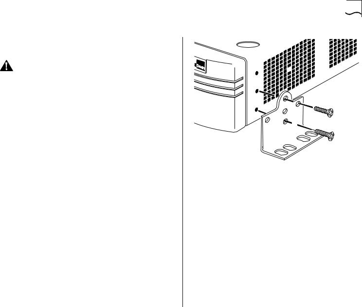
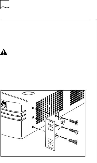
Wall Mounting
A single Switch can be wall-mounted.
CAUTION: Disconnect any cables from the unit before continuing. Remove self-adhesive pads from the underside of the unit if they have been previously fitted.
1Place the Switch the right way up on a hard flat surface, with the front facing towards you.
2Locate a mounting bracket over the mounting holes on one side of the unit, as shown in Figure 2-3.
3Insert the two screws and tighten with a suitable screwdriver.
4Repeat for the other side of the unit.
5Ensure that the wall you are going to use is smooth, flat, dry and sturdy. Attach a piece of plywood, approximately 305mm x 510mm x 12mm (12in. x 20in. x 0.5in.) securely to the wall if necessary, and mount the Switch as follows:
a Position the base of the unit against the wall (or plywood) ensuring that the ventilation holes face sidewards. Mark on the wall the position of the screw holes in both wall brackets. Drill the four holes.
b Using suitable fixings and screws (not provided), attach the Switch unit securely to the wall or plywood.
c Connect network cabling.
Installing the Switch 3000 TX |
2-5 |
|
|
|
|
Figure 2-3 Fitting a bracket for wall mounting

2-6 CHAPTER 2: INSTALLATION AND SETUP
Powering-Up the Switch
1Connect the power cord to the IEC socket on the rear of the Switch, and to your mains socket.
The Switch has no ON/OFF switch; the only method of connecting or disconnecting mains power is through the power cord.
2The Switch enters a Power On Self Test (POST). The time taken for the test to complete is dependent on the type of POST configured (refer to “Switch Management Setup” on page 3-9 for details of how to configure the type of POST). For a new Switch that is being installed for the first time, power-up takes approximately 15 seconds.
3Check the status LEDs to ensure the Switch is operating correctly (refer to “LEDs” on page 1-7).
Connecting a Redundant Power System (RPS)
You can connect a Redundant Power System (RPS) to the Switch.
At +5V, the current requirement for the Switch is 4.8A, excluding a Plug-in Module. Check the documentation supplied with your Plug-in Module for power consumption figures.
For most configurations, you need only one SuperStack II RPS output, and this can be connected to either of the two sockets on the rear of the unit.
If the current consumption of the Switch plus any Plug-in Module exceeds the capability of the RPS (8.5A), you need a SuperStack II Advanced RPS with one Advanced RPS 100W module.
If the RPS is used incorrectly, its Output Fault LED lights yellow.
You should check the documentation supplied with the RPS or Advanced RPS to see if the outputs can be used in parallel.

Connecting Equipment to the Console Port
The Switch console port settings are set to:
■8 data bits
■no parity
■1 stop bit
The terminal connected to the console port on the Switch must be configured with the same settings. This procedure is described in the documentation supplied with the terminal. If you have enabled auto-configuration for the Switch, the terminal’s line speed (baud rate) is detected automatically.
Connection to the console port can be direct for local management, or through a modem for remote management. The maximum baud rate the auto-configuration detects is 19,200 baud.
Appropriate cables are available from your local supplier. If you need to make your own cables, pin-outs are detailed in Appendix D.
Connecting Equipment to the Console Port |
2-7 |
Connecting a VT100 Terminal
To connect a VT100 terminal directly to the console port on the Switch, you need a standard null modem cable:
1Connect one end of the cable to the console port on the Switch, and the other to the console port on the VT100 terminal.
2Ensure that your terminal is set to:
■8 data bits
■no parity
■1 stop bit
If auto-configuration is enabled for the Switch, the terminal’s line speed (baud rate) is detected automatically.
Connecting a VT100 Terminal Emulator
1Ensure that the workstation is running a suitable terminal emulation package. There are many available; contact your local supplier for further details.
2If you are using a PC, you need a null modem cable with an appropriate connector. Connect one end of the cable to the workstation, and the other end to the console port on the Switch.
3Ensure that your workstation is set to:
■8 data bits
■no parity
■1 stop bit
If auto-configuration is enabled for the Switch, the workstation’s line speed (baud rate) is detected automatically.

2-8 CHAPTER 2: INSTALLATION AND SETUP
Connecting a Workstation Running SLIP
You can communicate with the Switch via the console port from a workstation running SLIP (Serial Line Internet Protocol). In this way, you can perform out-of-band management using Telnet or SNMP.
Cables required for this connection depend on the type of workstation you are using. You must configure the workstation to run SLIP. Refer to the documentation supplied with the workstation for more details.
You must configure the console port of the Switch to accept SLIP and set up the SLIP parameters (address and subnet mask). Refer to “Switch Management Setup” on page 3-9.
You may need a 5-wire cable when running SLIP. Two of the wires are required for Flow Control.

3 SETTING UP FOR MANAGEMENT
Methods of Managing the Switch 3000 TX
You can manage the Switch in four ways:
■Using the VT100 interface by connecting a VT100 terminal (or workstation with terminal emulation software) to the Switch console port.
■Using the VT100 interface over a TCP/IP network using a workstation running VT100 terminal emulation and Telnet.
■Using the VT100 interface by connecting a workstation running SLIP to the Switch console port.
■Using an SNMP Network Manager over a network running either the IP or IPX protocol. Each Network Manager provides its own user interface to the management facilities.
Using the VT100 Management Interface
The menu-driven user interface built into the Switch is known as the VT100 or local management interface. The VT100 management interface gives a forms-based structure with pre-defined security levels, enabling access to be restricted to particular users.
The Switch can support up to four management user sessions concurrently (for example, one console port and three Telnet connections).
You can establish VT100 management communication with the Switch through two different interfaces:
■Via the Console Port — You can access the local management interface using a VT100 terminal, or PC using suitable terminal emulation software. The terminal can be connected directly to the Switch, or via a modem. You can also connect a management workstation running SLIP to the console port, which allows you to use out-of-band Telnet. The workstation can be connected directly or remotely, via a modem. This method provides a way of managing the Switch in situations where the LAN is not providing a reliable service, or where the Network Manager does not have direct LAN connectivity or when a Network Manager does not support SNMP.
■Via a Network Connection — The local management facility is also accessible via Telnet over a network running the TCP/IP protocol. The management available through Telnet is exactly the same as that of a locally connected terminal. The Telnet application requires a VT100 terminal or PC with VT100 emulation software.

3-2 CHAPTER 3: SETTING UP FOR MANAGEMENT
Using Telnet
Any Telnet facility that emulates a VT100 terminal should be able to communicate with the Switch over a TCP/IP network. Up to three active Telnet sessions can access the Switch concurrently. If a connection to a Telnet session is lost inadvertently, the connection is closed by the Switch after 2–3 minutes of inactivity.
Before you can start a Telnet session you must set up the IP parameters described in “Switch Management Setup” on page 3-9.
To open the Telnet session, you must specify the IP address of the device that you want to manage. Check the user manual supplied with the Telnet facility if you are unsure how to do this.
Once the connection is established, the main banner of the VT100 management interface is displayed and you can log on.
Managing Over The Network
Any Network Manager running the Simple Network Management Protocol (SNMP) can manage the Switch, provided the MIB (Management Information Base) is installed correctly on the management workstation.
Each Network Manager provides its own user interface to the management facilities. 3Com's Transcend® range of Network Managers all have facilities for managing the Switch.
The Switch supports SNMP over both IP and IPX protocols.
IP Addresses
If you are uncertain about IP addresses that may be assigned to your devices, contact your network administrator first.
To operate correctly, each device on your network must have a unique IP address. IP addresses have the format n.n.n.n where n is a decimal number between 0 and 255. An example IP address is: 191.128.40.120
The IP address can be split into two parts:
■The first part (191.128 in the example) identifies the network on which the device resides.
■The second part (40.120 in the example) identifies the device within the network.
Loading...