


 Loading...
H3C SecPath U200 Series Unified Threat
Management Products
Installation Manual
Hangzhou H3C Technologies Co., Ltd.
http://www.h3c.com
Manual Version: 5PW101-20090520
Copyright © 2009, Hangzhou H3C Technologies Co., Ltd. and its licensors
All Rights Reserved
No part of this manual may be reproduced or transmitted in any form or by any means without prior written consent of Hangzhou H3C Technologies Co., Ltd.
Trademarks
H3C,  , Aolynk,
  , H3Care,
  , TOP G,
  , IRF, NetPilot, Neocean, NeoVTL, SecPro, SecPoint, SecEngine, SecPath, Comware, Secware, Storware, NQA, VVG, V2G, VnG, PSPT, XGbus, N-Bus, TiGem, InnoVision and HUASAN are trademarks of Hangzhou H3C Technologies Co., Ltd.
All other trademarks that may be mentioned in this manual are the property of their respective owners.
Notice
The information in this document is subject to change without notice. Every effort has been made in the preparation of this document to ensure accuracy of the contents, but all statements, information, and recommendations in this document do not constitute the warranty of any kind, express or implied.
Technical Support
customer_service@h3c.com
http://www.h3c.com
About This Manual
Organization
H3C SecPath U200 Series Unified Threat Management Products Installation Manual is organized as follows:
|
Chapter |
Contents |
|
1 |
Product Overview |
Briefly introduces the product specifications, as well as the features |
|
and applications of the H3C SecPath U200 series UTM devices. |
|||
|
|
||
|
|
|
|
2 |
Interface Modules |
Describes the interface cards and interface modules supported by |
|
the H3C SecPath U200 series UTM devices. |
|||
|
|
||
|
|
|
|
|
|
Describes the site requirements for installing the H3C SecPath U200 |
|
3 |
Preparing for Installation |
series UTM devices, safety recommendations before and during |
|
|
|
installation, and required tools. |
|
|
|
|
|
4 |
Installing the U200 Series |
Introduces how to install an H3C SecPath U200 series UTM device, |
|
as well as how to connect the power cable, console cable, Ethernet |
|||
Device |
|||
cable, and interface cable. |
|||
|
|
||
|
|
|
|
5 |
Starting and Configuring |
Describes how to boot and configure an H3C SecPath U200 series |
|
UTM device, including device startup, power-on, and initialization of |
|||
the U200 Series Device |
|||
system files. |
|||
|
|
||
|
|
|
|
|
|
Introduces how to maintain software of the H3C SecPath U200 |
|
6 |
Maintaining Software |
series UTM devices, including upgrading software and updating |
|
|
|
configuration files. |
|
|
|
|
|
7 |
Maintaining Hardware |
Introduces how to maintain hardware of the H3C SecPath U200 |
|
series UTM devices. |
|||
|
|
||
|
|
|
|
|
|
Describes some problems you may encounter during installation and |
|
8 |
Troubleshooting |
startup of an H3C SecPath U200 series UTM device and how to |
|
|
|
solve them. |
|
|
|
|
|
Appendix Compliance and |
This section introduces part of the compliance and safety |
||
precautions that should be followed during the installation and |
|||
Safety Manual |
|||
maintenance of the equipment. |
|||
|
|
||
|
|
|
|
Conventions
The manual uses the following conventions:
Command conventions
Convention |
Description |
|
Boldface |
The keywords of a command line are in Boldface. |
|
|
|
|
italic |
Command arguments are in italic. |
|
|
|
|
[ ] |
Items (keywords or arguments) in square brackets [ ] are optional. |
|
|
|
|
{ x | y | ... } |
Alternative items are grouped in braces and separated by vertical bars. |
|
One is selected. |
||
|
||
|
|
|
[ x | y | ... ] |
Optional alternative items are grouped in square brackets and |
|
separated by vertical bars. One or none is selected. |
||
|
||
|
|
|
{ x | y | ... } * |
Alternative items are grouped in braces and separated by vertical bars. |
|
A minimum of one or a maximum of all can be selected. |
||
|
||
|
|
|
Convention |
|
Description |
|
[ x | y | ... ] * |
|
Optional alternative items are grouped in square brackets and |
|
|
separated by vertical bars. Many or none can be selected. |
|
|
|
|
|
|
|
|
|
|
&<1-n> |
|
The argument(s) before the ampersand (&) sign can be entered 1 to n |
|
|
times. |
|
|
|
|
|
|
|
|
|
# |
|
A line starting with the # sign is comments. |
|
|
|
|
|
GUI conventions
Convention |
Description |
|
Boldface |
Window names, button names, field names, and menu items are in |
|
Boldface. For example, the New User window appears; click OK. |
||
|
||
|
|
|
> |
Multi-level menus are separated by angle brackets. For example, File > |
|
Create > Folder. |
||
|
||
|
|
Symbols
Convention |
Description |
|
|
Means reader be extremely careful. Improper operation may cause bodily injury.
Means reader be careful. Improper operation may cause data loss or damage to equipment.
Means a complementary description.
Related Documentation
In addition to this manual, each H3C SecPath Series Security Products documentation set includes the following:
|
Manual |
|
Description |
|
H3C SecPath Series Security |
|
Describes the features, operation fundamentals, and configuration |
|
|
commands of the H3C SecPath series security products, guides |
|
|
Products User Manual |
|
|
|
|
you to make configuration, and provides configuration examples. |
|
|
|
|
|
|
|
|
|
Obtaining Documentation
You can access the most up-to-date H3C product documentation on the World Wide Web at this URL: http://www.h3c.com.
The following are the columns from which you can obtain different categories of product documentation:
[Products & Solutions]: Provides information about products and technologies.
[Technical Support & Document > Technical Documents]: Provides several categories of product documentation, such as installation, configuration, and maintenance.
[Technical Support & Document > Software Download]: Provides the documentation released with the software version.
Documentation Feedback
You can e-mail your comments about product documentation to info@h3c.com.
We appreciate your comments.
Environmental Protection
This product has been designed to comply with the requirements on environmental protection. For the proper storage, use and disposal of this product, national laws and regulations must be observed.
Table of Contents
1 Product Overview ······································································································································1-1
Introduction ·············································································································································1-1 Features ··········································································································································1-1 Physical Description································································································································1-2 U200-A ············································································································································1-2 U200-M············································································································································1-3 U200-S ············································································································································1-4 Technical Specifications··························································································································1-5 Processor and Storages··················································································································1-5 Dimensions and Weight···················································································································1-5 Fixed Interfaces and Slots···············································································································1-6 Power Input ·····································································································································1-6 Operating Environment Specifications ····························································································1-6 Components············································································································································1-7 Processor and Storages··················································································································1-7 Front Panel LEDs ····························································································································1-7 Fixed Interfaces·······························································································································1-8 AC Power Input ·····························································································································1-14 Clock··············································································································································1-14 Port Lightning Arrester (Optional)··································································································1-14 Power Lightning Arrester (Optional)······························································································1-15 Signal Lightning Arrester (Optional) ······························································································1-15 System Software ···························································································································1-16
i

1 Product Overview
Introduction
The H3C SecPath U200 Series Unified Threat Management Products are new-generation UTM devices designed for enterprise users.
The U200 series comprises three models:
z
z
z
U200-A: Designed for largeand medium-sized enterprise users U200-M: Designed for medium-sized enterprise users
U200-S: Designed for smalland medium-sized enterprise users
In addition to traditional firewall functions, the U200 series protect network security by providing a wide range of functions including virtual firewall, security zone, intrusion detection and protection, gateway anti-virus, anti-spam, P2P traffic control, and URL filtering. With the application specification packet filter (ASPF) technology, a U200 series device can monitor connection setup processes and illegal operations, and dynamically filter packets based on ACLs. Moreover, the U200 series support multiple VPN services including IPSec VPN, L2TP VPN, and GRE VPN, and thereby can be used for constructing a variety of VPN networks. The series deliver abundant routing capabilities and support RIP and OSPF. Adopting a high-performance multi-core CPU, the U200-A, U200-M and U200-S can support up to 10, 8, and 7 GE interfaces respectively, delivering high scalability for user investment protection.
The U200 series are available with AC power supply to ensure high reliability, fully satisfy requirements for network maintenance, update, and optimization, support detection of chassis internal temperature, support network management, and provide a Web management interface.
The U200-A provides two MIM expansion slots for future service expansion. Currently, the slots support the NSQ1GT2UA0 and NSQ1GP4U0 MIM modules.
The U200-M provides one MIM expansion slot and currently supports the same MIM as the U200-A does.
The U200-S provides a mini expansion slot for future service expansion. Currently, the device supports the 2-GE and NSQ1WLAN0 interface modules.
Features
The U200 series deliver the following features:
Powerful hardware platform
The U200 series perfectly fit in enterprise networks thanks to the adoption of MIPS64-based CPUs and integrated high-performance hardware-based VPN accelerators.
Abundant security protection functions
zSecurity zone management: You can create security zones based on physical interfaces, logical interfaces, Layer-2 Ethernet interfaces, or combinations of Layer-2 Ethernet interfaces and VLANs. Interfaces belonging to the same security zone share the same security requirements in security
1-1
policy control. With security zones, security administrators can classify interfaces with different security requirements into different zones. This simplifies policy maintenance and separates network services and security services.
zPacket filtering: Applies standard or extended ACL rules between security zones to implement packet filtering based on UDP or TCP port information. You can also implement packet filtering based on time ranges.
zApplication specific packet filter (ASPF): Dynamically determines whether to forward or drop a packet by checking its application layer protocol information (such as FTP, HTTP, SMTP, RTSP, or any other application layer protocol carried on TCP/UDP), monitoring the status of connection-oriented application layer protocols, and maintaining status information for each connection.
zP2P traffic control: Performs in-depth packet inspection to identify and manipulate P2P traffic. With various control policies, a U200 series device controls P2P traffic flexibly.
zVirtual firewall: You can create multiple virtual firewalls, each implementing a separate security policy. These virtual firewalls are isolated from one another and thus can be managed separately.
zDiverse attack prevention functions: Guards against attacks including Land, Smurf, Fraggle, WinNuke, Ping of Death, Tear Drop, IP Spoofing, IP fragment, fragment, TCP flag invalid, large ICMP packet, IP Sweep, port scan, and DDoS attacks such as SYN Flood, UDP Flood, and ICMP Flood.
zPacket filtering: Blocks specified URLs to better utilize network resources.
Powerful VPN functions
zIPSec and GRE
zIKE and PKI
zA built-in hardware-based VPN encryption engine, ensuring high-performance VPN processing
Physical Description
U200-A
Front view
Figure 1-1 U200-A front view
|
|
|
|
|
|
|
|
|
|
|
|
|
|
|
|
|
|
|
|
|
|
|
|
|
|
|
|
|
|
|
|
|
|
|
|
|
|
|
|
|
|
|
|
|
|
|
|
|
|
|
|
|
|
|
|
|
|
|
|
|
|
|
|
|
|
|
|
|
|
|
|
|
|
|
|
|
|
|
|
|
|
|
|
|
|
|
|
|
|
|
|
|
|
|
|
|
|
|
|
|
|
|
|
|
|
|
|
|
|
|
|
|
|
|
|
|
|
|
|
|
|
|
|
|
|
|
|
|
|
|
|
|
|
|
|
|
|
|
|
|
|
|
|
|
|
|
|
|
|
|
|
|
|
|
|
|
|
|
|
|
|
|
|
|
|
|
|
|
|
|
|
|
|
|
|
|
|
|
|
|
|
|
|
|
|
|
|
|
|
|
|
|
|
|
|
|
|
|
|
|
|
|
|
|
|
|
|
|
|
|
|
|
|
|
|
|
|
|
|
(1) |
10/100/1000 Mbps electrical Ethernet |
|
|
|
|
|
(2) 10/100/1000 Mbps electrical Ethernet |
||||||||||||||||||||||||||||||||||||
interface 0 |
|
|
|
|
|
interface 1 |
|||||||||||||||||||||||||||||||||||||
(3) |
10/100/1000 Mbps electrical Ethernet |
|
|
|
|
|
(4) 10/100/1000 Mbps electrical Ethernet |
||||||||||||||||||||||||||||||||||||
interface 2 |
|
|
|
|
|
interface 3 |
|||||||||||||||||||||||||||||||||||||
(5) |
10/100/1000 Mbps electrical Ethernet |
|
|
|
|
|
(6) 10/100/1000 Mbps electrical Ethernet |
||||||||||||||||||||||||||||||||||||
interface 4 |
|
|
|
|
|
interface 5 |
|||||||||||||||||||||||||||||||||||||
(7) |
Console port (CONSOLE) |
|
|
|
|
|
(8) USB interface |
||||||||||||||||||||||||||||||||||||
(9) |
CF card ejector button |
|
|
|
|
|
(10) CF card slot |
||||||||||||||||||||||||||||||||||||
(11) |
System LED (SYS) |
|
|
|
|
|
(12) Slot 2 LED (SLOT2) |
||||||||||||||||||||||||||||||||||||
(13) |
Slot 1 LED (SLOT1) |
|
|
|
|
|
(14) Power LED (PWR) |
||||||||||||||||||||||||||||||||||||
(15) |
CF card LED (CF) |
|
|
|
|
|
|
|
|
|
|||||||||||||||||||||||||||||||||
|
|
|
|
|
|
|
|
|
|
|
|
|
|
|
|
|
|
|
|
|
|
|
|
|
|
|
|
|
|
|
|
|
|
|
1-2 |
|
|
|
|
|
|||

Rear view
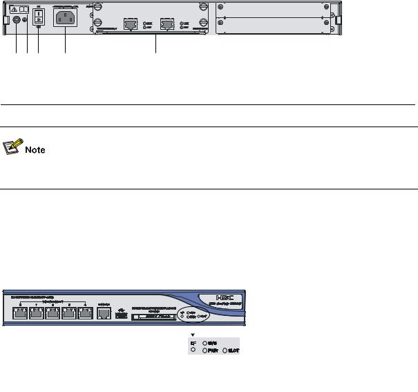
Figure 1-2 U200-A rear view
(1) |
(2) |
(3) |
(4) |
(5) |
(6) |
|
(1) |
Grounding screw and symbol |
(2) OPEN BOOK symbol |
|
|
|
(3) |
AC power switch (ON/OFF) |
(4) |
AC power socket |
|
|
(5) |
Slot 1 (with an NSQ1GT2UA0 module |
(6) |
Slot 2 (with an NSQ1GT2UA0 module |
|
|
installed) |
installed) |
|
||
|
|
|
|
|
|
The open book symbol is used to remind the operator to read the relevant chapters when performing any of these operations on the U200-A:
zConnecting the ESD-preventive wrist strap
zInstalling the device on a workbench or in a rack
zConnecting the PGND cable or the AC power cord
zConnecting the power lightning arrester, signal lightning arrester, or port lightning arrester
zConnecting the console cable, AUX cable, or Ethernet cables
zOpening and closing the chassis cover
zInstalling or removing the mini card (available only on the U200-S), MIM module (available only on the U200-A and U200-M), or CF card
U200-M
Front view
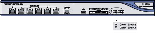
Figure 1-3 U200-M front view
|
|
|
|
|
|
|
|
|
|
|
|
|
|
|
|
|
|
|
|
|
|
|
|
|
|
|
|
|
|
|
|
|
|
|
|
|
|
|
|
|
|
|
|
|
|
|
|
|
|
|
|
|
|
|
|
|
|
|
|
|
|
|
|
|
|
|
|
|
|
|
|
|
|
|
|
|
|
|
|
(1) |
10/100/1000 Mbps electrical Ethernet |
|
|
|
|
|
|
(2) 10/100/1000 Mbps electrical Ethernet |
|||||||||||
interface 0 |
|
|
|
|
|
|
interface 1 |
||||||||||||
(3) |
10/100/1000 Mbps electrical Ethernet |
|
|
|
|
|
|
(4) 10/100/1000 Mbps electrical Ethernet |
|||||||||||
interface 2 |
|
|
|
|
|
|
interface 3 |
||||||||||||
(5) |
10/100/1000 Mbps electrical Ethernet |
|
|
|
|
|
|
(6) 10/100/1000 Mbps electrical Ethernet |
|||||||||||
interface 4 |
|
|
|
|
|
|
interface 5 |
||||||||||||
(7) |
Console port (CONSOLE) |
|
|
|
|
|
|
(8) USB interface |
|||||||||||
(9) |
CF card ejector button |
|
|
|
|
|
|
(10) |
CF card slot |
||||||||||
(11) System LED (SYS) |
|
|
|
|
|
|
(12) |
Slot 1 LED (SLOT1) |
|||||||||||
(13) Power LED (PWR) |
|
|
|
|
|
|
(14) |
CF card LED (CF) |
|||||||||||
|
|
|
|
|
|
|
|
|
1-3 |
|
|
|
|
|
|
|
|||
Rear view
Figure 1-4 U200-M rear view
(1) |
Grounding screw and symbol |
(2) OPEN BOOK symbol |
(3) |
AC power switch (ON/OFF) |
(4) AC power socket |
(5) Slot 1 (with an NSQ1GT2UA0 module installed)
For detailed description of the OPEN BOOK symbol, refer to the note under Figure 1-2.
U200-S
Front view
Figure 1-5 U200-S front view
|
|
|
|
|
|
|
|
|
|
|
|
|
|
|
|
|
|
|
|
|
|
|
|
|
|
|
|
|
|
|
|
|
|
|
|
|
|
|
|
|
|
|
|
|
|
|
|
|
|
|
|
|
|
|
|
|
|
|
|
|
|
|
|
|
|
|
|
|
|
|
|
|
|
|
|
|
|
|
|
|
|
|
|
|
|
|
|
|
|
|
|
|
|
|
|
|
|
|
|
|
|
|
|
|
|
|
|
|
|
|
|
|
|
|
|
|
|
|
|
|
|
|
|
|
|
|
|
|
|
|
|
|
|
|
|
|
|
|
|
|
|
|
|
|
|
|
|
|
|
|
|
|
|
|
|
|
|
|
|
|
|
|
|
|
|
|
|
|
|
|
|
|
|
|
|
|
|
|
|
|
|
|
|
|
|
|
|
|
|
|
|
|
|
|
|
|
|
|
|
|
|
|
|
|
|
|
|
|
|
|
|
|
|
|
|
|
|
|
|
|
|
|
|
|
|
|
|
|
|
|
|
|
|
|
|
|
|
|
|
|
|
|
|
|
|
|
|
|
|
|
|
|
|
|
|
|
|
|
|
|
|
|
|
|
|
|
|
|
|
|
|
|
|
|
|
|
|
|
|
|
|
|
|
|
|
|
(1) |
10/100/1000 Mbps electrical Ethernet |
|
(2) |
10/100/1000 Mbps electrical Ethernet |
||||||||||||||||||||||||||||||||||||
|
interface 0 |
|
|
interface 1 |
||||||||||||||||||||||||||||||||||||
(3) |
10/100/1000 Mbps electrical Ethernet |
|
|
(4) |
10/100/1000 Mbps electrical Ethernet |
|||||||||||||||||||||||||||||||||||
|
interface 2 |
|
|
interface 3 |
||||||||||||||||||||||||||||||||||||
(5) |
10/100/1000 Mbps electrical Ethernet |
|
|
(6) |
Console port (CONSOLE) |
|||||||||||||||||||||||||||||||||||
|
interface 4 |
|
||||||||||||||||||||||||||||||||||||||
|
|
|
|
|
||||||||||||||||||||||||||||||||||||
(7) |
USB interface |
|
|
(8) |
CF card ejector button |
|||||||||||||||||||||||||||||||||||
(9) |
CF card slot |
|
|
(10) System LED (SYS) |
||||||||||||||||||||||||||||||||||||
|
(11) Slot LED (SLOT) |
|
|
(12) Power LED (PWR) |
||||||||||||||||||||||||||||||||||||
|
(13) CF card LED (CF) |
|
|
|
|
|||||||||||||||||||||||||||||||||||
1-4
Rear view
Figure 1-6 U200-S rear view
|
|
|
|
|
|
|
|
|
|
|
|
|
|
|
|
|
|
|
|
|
|
|
|
|
|
|
|
|
|
|
|
|
|
|
|
|
|
|
|
|
|
|
|
|
(1) |
AC power socket |
|
|
(2) Slot (with 2GE) |
|
||||
|
(3) |
OPEN BOOK symbol |
|
|
(4) Grounding screw and sign |
|
||||
|
|
|
|
|
|
|
|
|
|
|
For detailed description of the open book symbol, refer to the note under Figure 1-2.
Technical Specifications
Processor and Storages
Table 1-1 Processor and storages of the U200 series
|
|
Item |
|
|
|
Description |
|
|
|
|
|
U200-A |
U200-M |
U200-S |
|
|
|
|
|
|
|||
|
|
Processor |
|
RMI XLS208 750 MHz |
|
RMI XLS404 800 MHz |
|
|
|
|
|
|
|
|
|
|
|
Flash |
|
32 MB |
|
|
|
|
|
|
|
|
|
|
|
|
|
Memory type and size |
|
DDR2 SDRAM |
|
DDR2 SDRAM |
|
|
|
|
1 GB by default |
|
512 MB by default |
||
|
|
|
|
|
|
||
|
|
|
|
|
|
||
|
|
External CF card |
256 MB, 512 MB, or 1 GB |
|
|
||
|
|
|
|
|
|
|
|
Dimensions and Weight
Table 1-2 Dimensions and weight of the U200 series
|
|
Item |
|
|
|
Description |
|
|
|
|
|
U200-A |
U200-M |
U200-S |
|
|
|
|
|
|
|||
|
|
Dimensions (H × W × D), |
|
|
|
43.6 × 300 × 260 |
|
|
|
excluding feet and |
|
44.2 × 442 × 400 mm (1.74 × 17.40 × 15.75 in.) |
mm (1.72 × 11.81 × |
||
|
|
mounting brackets |
|
|
|
10.24 in.) |
|
|
|
|
|
|
|
|
|
|
|
Weight (fully configured) |
|
5.9 kg (13.01 lb) |
5.5 kg (12.13 lb) |
2.22 kg (4.89 lb) |
|
|
|
|
|
|
|
|
|
1-5

Fixed Interfaces and Slots
Table 1-3 Interface (fixed) and slot specifications
|
|
Item |
|
|
|
|
|
|
Description |
|
|
|
|
|
|
|
|
|
U200-A |
|
|
U200-M |
|
|
U200-S |
|
|
|
|
|
|
|
|
|
|
|
|
|
|||
|
|
Console port |
1 |
(9600 bps to 115200 bps, 9600 bps by default) |
|
|
|
||||||
|
|
|
|
|
|
|
|
|
|
|
|
|
|
|
|
USB |
1 |
(host mode, reserved without software support) |
|
|
|
||||||
|
|
interface |
|
|
|
||||||||
|
|
|
|
|
|
|
|
|
|
|
|
||
|
|
|
|
|
|
|
|
|
|||||
|
|
GE |
6 |
(GE0 to GE5) |
|
|
|
5 (GE0 to GE4) |
|||||
|
|
interfaces |
|
10/100/1000 Mbps electrical interfaces, MDI/MDIX autosensing |
|||||||||
|
|
|
|
|
|||||||||
|
|
|
|
|
|
|
|||||||
|
|
CF card slot |
1 external CF card slot (256 MB, 512 MB, or 1 GB) |
|
|
|
|||||||
|
|
|
|
|
|
|
|
|
|
||||
|
|
|
|
2 |
MIM expansion slots |
|
1 MIM expansion slot |
|
1 Mini expansion slot |
||||
|
|
Slots |
|
Available interface module: |
|
Available interface module: |
|
Available interface |
|||||
|
|
|
NSQ1GT2UA0 and |
|
NSQ1GT2UA0 and |
|
module: 2GE and |
||||||
|
|
|
|
|
|
|
|||||||
|
|
|
|
|
NSQ1GP4U0 |
|
NSQ1GP4U0 |
|
NSQ1WLAN0 |
||||
|
|
|
|
|
|
|
|
|
|
|
|
|
|
Power Input
Table 1-4 Input voltage specifications
|
|
Item |
|
|
Description |
|
|
|
|
U200-A |
U200-M |
U200-S |
|
|
|
|
|
|||
|
|
Rated voltage range |
100 VAC to 240 VAC; 50 Hz or 60 Hz |
|
||
|
|
|
|
|
|
|
|
|
Maximum input current |
1.6 A |
|
0.6 A |
|
|
|
|
|
|
|
|
|
|
Maximum power |
100 W |
|
54 W |
|
|
|
|
|
|
|
|
Operating Environment Specifications
Table 1-5 Operating environment specifications
|
|
Item |
|
|
|
|
|
Description |
|
|
|
|
|
|
|
|
U200-A |
|
|
U200-M |
|
|
U200-S |
|
|
|
|
|
|
|
|
|
|
|
|
|||
|
|
Operating temperature |
|
0°C to 45°C (32°F to 113°F) |
|
|
|
|
|
|||
|
|
|
|
|
|
|
|
|
|
|
|
|
|
|
Operating humidity |
|
10% to 95% |
|
|
|
|
|
|||
|
|
(noncondensing) |
|
|
|
|
|
|
||||
|
|
|
|
|
|
|
|
|
|
|
||
|
|
|
|
|
|
|
|
|
|
|
|
|
|
|
Operating altitude |
|
–60 to 3000 m (–196.85 to +9842.52 ft.) |
|
–60 to 2000 m (–196.85 |
||||||
|
|
|
|
to +6561.68 ft.) |
||||||||
|
|
|
|
|
|
|
|
|
|
|
||
|
|
|
|
|
|
|
|
|
|
|
|
|
1-6
Components
Processor and Storages
Processor
A U200 series device uses a multi-core microprocessor as its data forwarding and service processing engine.
Flash
A U200 series device uses a 32 MB flash for storing BootWare and APP.
Memory
The memory temporarily stores data for the running system and buffering data to be forwarded. By default, the U200-A and U200-M are equipped with a 1 GB memory while the U200-S has a 512 MB memory.
Front Panel LEDs
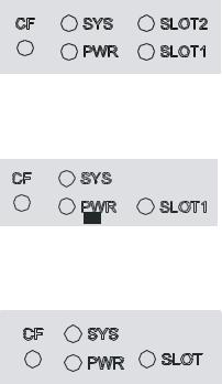
Figure 1-7 U200-A front panel LEDs
Figure 1-8 U200-M front panel LEDs
Figure 1-9 U200-S front panel LEDs
Table 1-6 Description of the front panel LEDs
|
LED |
Status |
Description |
|
|
Off |
No CF card is in position or the CF card cannot be |
|
|
identified. |
|
|
|
|
|
|
|
|
|
|
CF (green) |
On |
A CF card is in position and has passed the test. It can |
|
be removed in this state. |
||
|
|
|
|
|
|
|
|
|
|
Blinking |
The system is accessing the CF card. Do not unplug |
|
|
the card in this state. |
|
|
|
|
|
|
|
|
1-7 |
|
|
LED |
|
Status |
|
Description |
|
|
|
|
Off |
|
The system is powered off or faulty. |
|
|
|
|
|
|
|
|
|
SYS (green) |
|
Slow blinking (at 1 Hz) |
|
The interface module is operating normally as |
|
|
|
|
configured. |
||
|
|
|
|
|
|
|
|
|
|
|
|
|
|
|
|
|
|
Fast blinking (at 8 Hz) |
Software is being loaded or the system is not working. |
|
|
|
|
|
|
|
|
|
|
PWR (green) |
|
Off |
|
The power module is not working or faulty. |
|
|
|
|
|
|
|
|
|
|
On |
The power module is supplying power normally. |
||
|
|
|
|
|||
|
|
|
|
|
|
|
|
|
|
|
Off |
|
No interface module is in the slot or the interface |
|
|
SLOT1/SLOT2/ |
|
|
module is faulty. |
|
|
|
|
|
|
||
|
|
SLOT (green) |
|
On |
|
An interface module is in the slot and operating |
|
|
|
|
|
||
|
|
|
|
|
normally. |
|
|
|
|
|
|
|
|
|
|
|
|
|
|
|
Fixed Interfaces
Table 1-7 Description of the fixed interfaces
Interface |
|
|
Description |
||
Console port |
|
1 |
|
|
|
|
|
|
|
|
|
USB interface |
|
1 |
|
Host mode, reserved without software support |
|
|
|
|
|
|
|
|
U200-A |
6 |
|
10/100/1000 Mbps electrical Ethernet interfaces: GE0 to GE5 |
|
GE |
|
|
|
|
|
U200-M |
6 |
|
10/100/1000 Mbps electrical Ethernet interfaces: GE0 to GE5 |
||
interfaces |
|
||||
|
|
|
|
||
|
U200-S |
5 |
|
10/100/1000 Mbps electrical Ethernet interfaces: GE0 to GE4 |
|
|
|
|
|
||
|
|
Three CF card options of different memory sizes are available: |
|||
CF card slot |
1 |
z |
256 MB |
||
z |
512 MB |
||||
|
|
||||
|
|
z |
1 GB |
||
Console port
1)Introduction
A U200 series device provides an RS232 asynchronous serial console port (Console), which can be connected to a computer for system debugging, configuration, maintenance, management, and software loading.
2)Specifications
Table 1-8 Technical specification of the console port
Attribute |
Description |
Connector type |
RJ-45 |
|
|
Interface standard |
Asynchronous EIA/TIA-232 |
|
|
Baud rate |
9600 bps (default) to 115200 bps |
|
|
Maximum transmission distance |
15 m (49.21 ft.) |
|
|
1-8
Attribute |
Description |
|
|
Connection to an ASCII terminal
Services Connection to the serial interface of a local PC to run the terminal emulation program
Command line interface
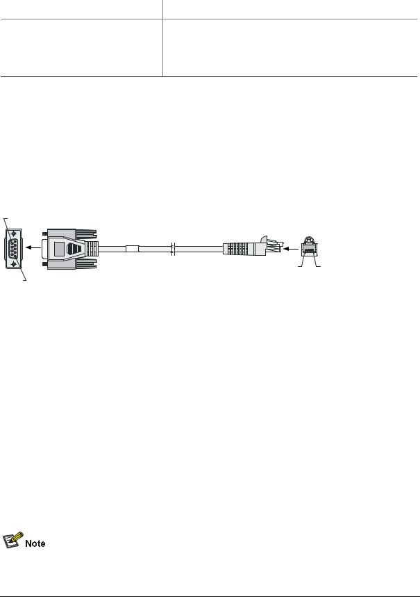
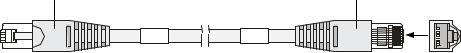
3)Console cable
The console cable is an 8-core shielded cable. The RJ-45 connector at one end of the cable is for the console port on the UTM device, and the DB-9 female connector at the other end is for the serial port on a configuration terminal.
Figure 1-10 illustrates the console cable.
Figure 1-10 Console cable
Table 1-9 Console cable pinouts
|
RJ-45 |
Signal direction |
DB9 |
Signal |
|
|
1 |
Æ |
8 |
CTS |
|
|
|
|
|
|
|
|
2 |
Æ |
6 |
DSR |
|
|
|
|
|
|
|
|
3 |
Æ |
2 |
RXD |
|
|
|
|
|
|
|
|
4 |
Å |
1 |
DCD |
|
|
|
|
|
|
|
|
5 |
— |
5 |
GND |
|
|
|
|
|
|
|
|
6 |
Å |
3 |
TXD |
|
|
|
|
|
|
|
|
7 |
Å |
4 |
DTR |
|
|
|
|
|
|
|
|
8 |
Å |
7 |
RTS |
|
|
|
|
|
|
|
|
|
|
|
|
|
For how to connect the console cable, refer to the “Connecting the Console Cable” section in Chapter 4 “Installing the U200 Series Device.”
Ethernet interfaces
1)Introduction
A UTM series device provides fixed 10/100/1000Base-T Ethernet interfaces on its front panel, the number of which depends on the device model. Each fixed Ethernet interface (RJ-45) uses two built-in
1-9
LEDs in the upper corners to indicate its status.
Table 1-10 Description of Ethernet interface LEDs
|
|
Status |
Description |
|
|
|
LINK |
Off |
No link is present. |
|
|
|
|
|
|
|
On |
A link is present. |
|
|
|
|
||
|
|
|
|
|
|
|
ACT |
Off |
No data is being received or transmitted. |
|
|
|
|
|
|
|
Blinking |
Data is being received or transmitted. |
|
|
|
|
||
|
|
|
|
|
2)Specifications
Table 1-11 Technical specifications of the Ethernet interfaces
|
Item |
|
Description |
|
|
|
Connector type |
RJ-45 |
|
|
|
|
|
|
|
|
|
|
Interface type |
Autosensing (Ethernet does not support MDI/MDIX autosensing when |
|
||
|
working in the forced mode) |
|
|
|
|
|
|
|
|
|
|
|
|
|
|
|
|
|
Frame format |
Ethernet_II |
|
|
|
|
Ethernet_SNAP |
|
|
|
|
|
|
|
|
|
|
|
|
|
|
|
|
|
|
10 Mbps (autosensing) |
|
Half-/full-duplex auto-negotiation |
|
|
Rate and negotiation |
|
|
|
|
|
100 Mbps (autosensing) |
|
Half-/full-duplex auto-negotiation |
|
|
|
mode |
|
|
||
|
|
|
|
|
|
|
|
1000 Mbps (autosensing) |
|
Full-duplex auto-negotiation |
|
|
|
|
|
|
|
|
|
|
|
|
|
The media dependent interface (MDI) standard is typically used for the Ethernet interfaces of network adaptors. The media dependent interface crossover (MDI-X) standard is typically used on hubs or LAN switches.
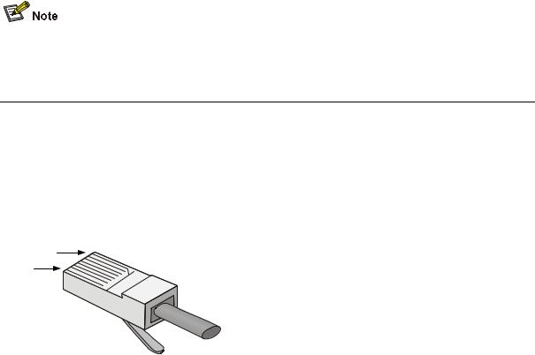
3)RJ-45 connector
The 10/100/1000Base-T Ethernet interfaces of the U200 series use RJ-45 connectors and support MDI/MDIX autosensing. Category-5 twisted pair cables are used for RJ-45 connectors. Figure 1-11 shows an RJ-45 connector.
Figure 1-11 RJ-45 connector
1-10
When working in the forced mode, Ethernet does not support MDI/MDIX autosensing.
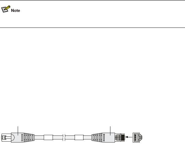
4)Cable connecting electrical Ethernet interfaces
Ethernet electrical interfaces usually use category-5 twisted pair cables. Ethernet cables fall into two categories:
zStandard cables: Also known as straight-through cables. At both ends of a standard cable, wires are crimped in the RJ-45 connectors in the same sequence. A straight-through cable is used for connecting a terminal (for example, a PC or UTM device) to a hub or LAN switch. Straight-through cables are shipped with the U200 series.
zCrossover cables: At both ends of a crossover cable, wires are crimped in the RJ-45 connectors in different sequences. A crossover cable is used for connecting two terminals (for example, two PCs or UTM devices). You can make crossover cables yourself as needed.
Figure 1-12 Ethernet cable
Table 1-12 Straight-through cable connector pinouts
|
RJ-45 |
|
|
Signal |
|
|
Category-5 |
|
Signal direction |
|
|
RJ-45 |
|
|
|
|
|
|
|
twisted pair |
|
|
|
|
|||||
|
|
|
|
|
|
|
|
|
|
|
|
|
||
|
|
|
|
|
|
|
|
|
|
|
|
|
|
|
1 |
|
|
TX+ |
|
White (Orange) |
Æ |
|
1 |
|
|||||
|
|
|
|
|
|
|
|
|
|
|
||||
2 |
|
|
TX- |
|
Orange |
Æ |
|
2 |
|
|||||
|
|
|
|
|
|
|
|
|
|
|
||||
3 |
|
|
RX+ |
|
White (Green) |
Å |
|
3 |
|
|||||
|
|
|
|
|
|
|
|
|
|
|||||
4 |
|
— |
|
Blue |
|
— |
4 |
|
||||||
|
|
|
|
|
|
|
|
|
|
|||||
5 |
|
— |
|
White (Blue) |
|
— |
5 |
|
||||||
|
|
|
|
|
|
|
|
|
|
|
||||
6 |
|
|
RX- |
|
Green |
Å |
|
6 |
|
|||||
|
|
|
|
|
|
|
|
|
|
|
||||
7 |
|
|
— |
|
White (Brown) |
|
— |
7 |
|
|||||
|
|
|
|
|
|
|
|
|
|
|||||
8 |
|
— |
Brown |
|
— |
8 |
|
|||||||
|
|
|
|
|
|
|
|
|
|
|
||||
Table 1-13 Crossover cable connector pinouts |
|
|
|
|
|
|
||||||||
|
|
|
|
|
|
|
|
|
|
|
|
|
|
|
|
RJ-45 |
|
|
Signal direction |
|
|
Category-5 |
|
|
Signal direction |
|
|
RJ45 |
|
|
|
|
|
|
twisted pair |
|
|
|
|
|
||||
|
|
|
|
|
|
|
|
|
|
|
|
|
|
|
|
|
|
|
|
|
|
|
|
|
|
|
|
|
|
1 |
|
|
TX+ |
|
White (Orange) |
Æ |
|
3 |
|
|||||
|
|
|
|
|
|
|
|
|
|
|||||
2 |
|
|
TX- |
|
Orange |
Æ |
|
6 |
|
|||||
|
|
|
|
|
|
|
|
|
|
|||||
3 |
|
|
RX+ |
|
White (Green) |
Å |
|
1 |
|
|||||
|
|
|
|
|
|
|
|
|
|
|
|
|
|
|
|
|
|
|
|
|
1-11 |
|
|
|
|
|
|
|
|
|
|
RJ-45 |
|
|
Signal direction |
|
|
Category-5 |
|
|
Signal direction |
|
|
RJ45 |
|
|
|
|
|
|
|
|
twisted pair |
|
|
|
|
|
|
||||
|
|
|
|
|
|
|
|
|
|
|
|
|
|
|
|
|
|
|
|
|
|
|
|
|
|
|
|
|
|
|
|
|
|
|
4 |
|
— |
|
Blue |
|
— |
4 |
|
|
||||||
|
|
|
|
|
|
|
|
|
|
|||||||
|
5 |
|
— |
White (Blue) |
|
— |
5 |
|
|
|||||||
|
|
|
|
|
|
|
|
|
|
|
|
|||||
|
6 |
|
|
RX- |
|
Green |
Å |
|
2 |
|
|
|||||
|
|
|
|
|
|
|
|
|
|
|
|
|||||
|
7 |
|
|
— |
|
White (Brown) |
|
— |
7 |
|
|
|||||
|
|
|
|
|
|
|
|
|
|
|
||||||
|
8 |
|
— |
|
Brown |
|
— |
8 |
|
|
||||||
|
|
|
|
|
|
|
|
|
|
|
|
|
|
|
|
|
|
|
|
|
|
|
|
|
|
|
|
|
|
|
|
|
|
zYou can refer to the tables above when trying to identify or preparing the two types of Ethernet cables.
zWhen preparing Ethernet cables, follow the color pairings in the tables. Otherwise, communication quality will be affected even if the two devices at both ends can communicate.
zWhen preparing Ethernet cables, use shielded cables preferentially for electromagnetic compatibility.
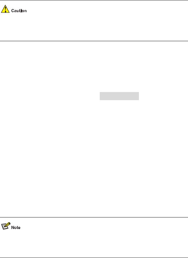
USB interface
USB interfaces can connect multiple types of devices and provide higher data transfer rates than common parallel interfaces and serial interfaces.
The U200 series support USB 2.0 to provide important storage and security functions. For example, with USB interfaces, you can provide large flash memory space for application programs, configuration files, and VPN certificates for setting up secure VPN connections and, secure distribution of configuration files.
In addition, USB interfaces provide a backup CF card mechanism to make file backup and restoration easy and reliable.
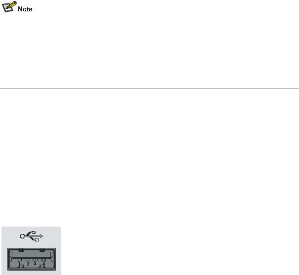
Figure 1-13 USB interface
The USB interface provided by a U200 series device is a USB 2.0 type-A interface. Serving as a host, it can connect an external USB device to expand the device's storage space for storing files and logs and in addition, facilitate file transfer.
1-12
zAt present, the USB interface provided on a U200 series device is a reserved module without software support.
zUse the USB flash drives provided by H3C only, because the U200 series may be incompatible with other USB flash drives.
zAvoid removing the USB flash drive when its LED is flashing. Doing so may cause the file system on the drive to get corrupted.
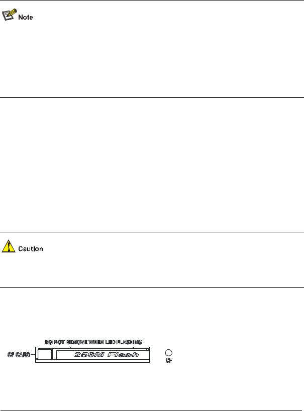
CF card
1)Introduction
A compact flash (CF) card is used for storing logs, host files, and configuration files. A U200 series device provides an external CF card slot for expanding storage space. Three CF card options of different memory sizes are available:
z256 MB
z512 MB
z1 GB
Use the CF cards provided by H3C only, because the U200 series may be incompatible with other CF cards.
2)CF card slot
Figure 1-14 CF card
|
|
|
|
|
|
|
|
|
|
|
|
|
|
|
|
|
|
|
|
|
|
|
|
|
|
|
|
|
|
|
|
|
|
|
|
|
|
|
|
|
|
|
|
|
|
|
|
|
|
|
|
|
|
|
|
|
|
|
|
|
|
|
|
|
|
|
(1) Ejector button |
|
(2) CF card slot |
|||||||
(3)CF card LED (CF)
3)CF card LED
For description of the CF card LED, see Table 1-6.
1-13
The CF card is hot-swappable. When the device is reading from or writing to the CF card or performing any other file system related operation, the CF card LED blinks. Do not unplug the CF card in this state because doing so can corrupt the file system in it.
AC Power Input
Table 1-14 lists the AC power specifications for the U200 series.
Table 1-14 AC power specifications
|
|
Item |
|
|
|
|
Description |
|
|
|
|
|
|
|
U200-A |
|
U200-M |
|
U200-S |
|
|
|
|
|
|
|
|
|
|
|||
|
|
Rated voltage range |
|
100 VAC to 240 VAC; 50 Hz or 60 Hz |
|
|
|
|||
|
|
|
|
|
|
|
|
|||
|
|
Maximum input current |
|
1.6 A |
|
|
0.6 A |
|||
|
|
|
|
|
|
|
|
|||
|
|
Maximum power |
|
100 W |
|
|
54 W |
|||
|
|
|
|
|
|
|
|
|
|
|
Clock
The U200 series are designed with a clock module for providing system time. You can set the system time at the command line interface.
The clock module can work despite power failure to ensure that the system time is correct at reboot. With the device powered off, the clock module can work for at least 10 years.
Note that:
zNever replace the clock module battery when power is present on the device.
zThe system time gets lost once the clock module battery is removed. You can set it at the command line interface.
You can use three commands including clock datetime, ock summer-time one-off (or clock summer-time repeating), and clock timezone to complete setting the system time. See the accompanying documentation for how to do that.
Port Lightning Arrester (Optional)
Before connecting an outdoor Ethernet cable to an Ethernet port, install a port lightning arrester to protect the device against lightning strikes.
The port lightning arresters available for the U200 series feature these:
1-14
zFor single-port use, maximum discharge current (8/20μs waveform): 5 kA, output voltage (10/700μs waveform): core-core < 40 V, core-ground < 600 V.
For the installation of the port lightning arrester, refer to the “Installing a Port Lightning Arrester” section in Chapter 4 “Installing the U200 Series Device.”
Power Lightning Arrester (Optional)
Before connecting an outdoor AC power cable to the device directly, you can connect the AC power input to a lightning protection busbar to protect the device against lightning strikes. In a heavy lightning area, you are recommended to install a power lightning arrester.
The lightning arresters available for the U200 series feature these:
zMaximum discharge current of 6500 A, protection for 500 VAC to 220 VAC.
For how to install a power lightning arrester, refer to the “Installing a Power Lightning Arrester (Optional)” section in Chapter 4 “Installing the U200 Series Device.”
Signal Lightning Arrester (Optional)
Generally, you need to install a signal lightning arrester between a signal cable and the connected device. This can protect electronic components against surge over-voltage resulting from lightning strikes or any other interferences, and minimize the impact on the system.
The following are specifications of the three signal lightning arrester options available for the U200 series:
zMaximum discharge current 2.5KA/protection voltage 25V-SMB-75J/SMB-75J-1W-10Mbps.
zMaximum discharge current 2.5KA/protection voltage 25V-BNC-75K/BNC-75K-10MBit/s.
zFor U-shape ports, maximum discharge current 3KA/common mode 400 V/differential mode 170V-RJ11
For how to install a signal lightning arrester, refer to the “Installing a Signal Lightning Arrester” section in Chapter 4 “Installing the U200 Series Device.“
1-15
System Software
The U200 series operate on the H3C Comware V5 or i-Ware software platform, integrating a rich set of security features including virtual firewall, attack prevention, load balancing, and P2P traffic management. Combining network and security technologies perfectly, the series can be deployed in various complex network environments to provide strong security protection.
1-16
Table of Contents
2 Interface Cards and Interface Modules ···································································································2-1
2GE Module ············································································································································2-1 NSQ1GT2UA0 Module····························································································································2-3 NSQ1GP4U0 Module······························································································································2-4 NSQ1WLAN0 Module ·····························································································································2-6 Arranging Slots and Naming Interfaces ··································································································2-7
Slot Arrangement·····························································································································2-7 Naming Interfaces ···························································································································2-7 Examples·········································································································································2-7
i
2 Interface Cards and Interface Modules
zCurrently, the U200 series do not support hot-swapping of interface modules.
zWith the hot swapping feature, you can remove an interface module after stopping it with the remove slot number command and then replacing the interface module or plugging in a new interface module as needed without powering off the device.
zCurrently the 2GE and NSQ1GT2UA0 interface modules are not available yet.
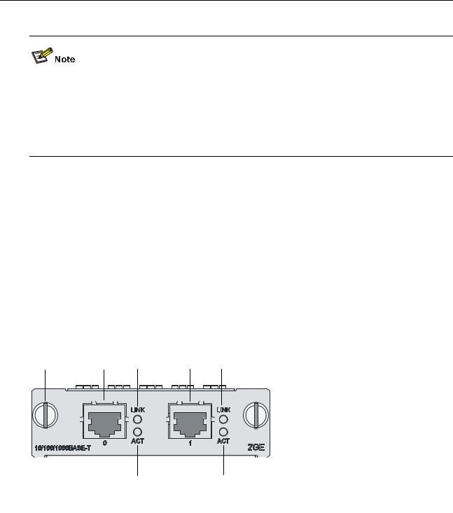
2GE Module
Introduction
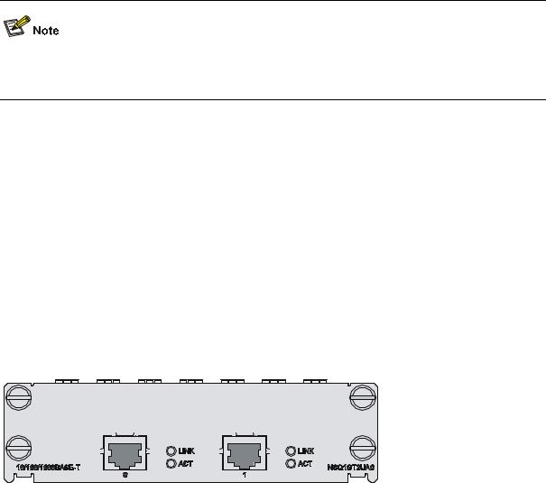
The 2GE module is a mini high-speed Layer 3 Gigabit Ethernet interface module. The 2GE module provides two RJ-45 electrical interfaces that support the Layer 3 routing function. Each interface on the 2GE module is available with a link LED and an activity LED for monitoring the link status and data transmission status. The 2GE module is connected to the processor through a 10-Gbps high-speed bus and can provide all functions of Layer 3 Ethernet interfaces with high performance.
Front view
Figure 2-1 2GE front view
(1) |
Captive screw |
(2) |
GE interface 0 |
|
(3) |
Link LED (LINK) of GE interface 0 |
(4) |
GE interface 1 |
|
(5) |
Link LED (LINK) of GE interface 1 |
(6) |
Data transmit/receive activity LED of GE interface 1 |
|
(ACT) |
||||
|
|
|||
(7) |
Data transmit/receive activity LED of |
GE interface 0 (ACT) |
||
2-1
LEDs
Table 2-1 Description of the LEDs on the front panel of the 2GE module
|
|
LED |
|
Status |
|
Description |
|
|
LINK |
|
Off |
|
No link is present. |
|
|
|
|
On |
|
A link is present. |
|
|
|
|
|
|
|
|
|
ACT |
|
Off |
|
No data is being transmitted or received. |
|
|
|
|
|
|
|
|
|
|
Blinking |
|
Data is being transmitted or received. |
|
|
|
|
|
|
||
|
|
|
|
|
|
|
Interface specifications
Table 2-2 Interface specifications of 2GE
|
|
Item |
|
|
Description |
|
|
|
Connector type |
RJ-45 |
|
|
|
|
|
|
|
|
|
|
|
|
Number of interfaces |
2 |
|
|
|
|
|
|
|
|
|
|
|
|
Interface standards |
|
802.3, 802.3u, 802.3ab |
|
|
|
|
|
|
|
|
|
|
|
|
|
Autosensing |
|
|
|
|
Interface type |
|
When working in the forced mode, Ethernet does not support |
||
|
|
|
|
MDI/MDIX autosensing. |
|
|
|
|
|
|
|
|
|
|
|
Frame formats |
|
Ethernet_II |
|
|
|
|
|
Ethernet_SNAP |
|
|
|
|
|
|
|
|
|
|
|
|
|
|
|
|
|
|
|
Maximum transmission |
|
100 m (328.08 ft.) over category-5 twisted pairs |
||
|
|
distance |
|
|||
|
|
|
|
|
|
|
|
|
|
|
|
|
|
|
|
|
|
10 Mbps (autosensing) |
|
Half-/full-duplex auto-negotiation |
|
|
Rate and negotiation mode |
|
|
|
|
|
|
|
100 Mbps (autosensing) |
|
Half-/full-duplex auto-negotiation |
|
|
|
|
|
|
|
|
|
|
|
|
1000 Mbps (autosensing) |
|
Full-duplex auto-negotiation |
|
|
|
|
|
|
|
Interface cable
The 2GE module uses a straight-through or crossover Ethernet cable for connection.
Figure 2-2 Ethernet cable
RJ-45 |
RJ-45 |
|
Connector |
Connector |
A |
|
|
|
|
1 |
A |
|
8 |
|
2-2
For how to connect the Ethernet cable, refer to the “Connecting an Ethernet cable for the 2GE module” section in Chapter 4 “Installing the U200 Series Device.”
NSQ1GT2UA0 Module
Introduction
The NSQ1GT2UA0 module is a MIM high-speed Layer 3 Gigabit Ethernet interface module. The module provides two RJ-45 electrical interfaces that support the Layer-3 routing function. Each interface on the NSQ1GT2UA0 module is available with a link LED and an activity LED for monitoring the link status and data transmission status. The NSQ1GT2UA0 module is connected to the processor through a PCIE high-speed bus to provide all functions of a Layer-3 Ethernet interface with high performance.
Front view
Figure 2-3 NSQ1GT2UA0 front view
|
|
|
|
|
|
|
|
|
|
|
|
|
|
|
|
|
|
|
|
|
|
|
|
|
|
|
|
|
|
|
|
|
|
|
|
|
|
|
|
|
|
|
|
|
|
|
|
|
|
|
|
|
|
|
|
|
|
|
|
|
|
|
|
|
|
|
(3) |
|
|
|
(6) |
|
|
|
|
|
|
||
(1) |
(2) |
(4) |
|
(5) |
(7) |
|
|
|
|
|
|
||||||||
|
|
|
|
|
|
|
|
|
|
|
|
|
|
|
|
|
|||
(1) |
Captive screw |
|
|
|
|
|
(2) |
GE interface 0 |
|||||||||||
(3) |
Link LED (LINK) of GE interface 0 |
|
|
(4) |
Data transmit/receive activity LED (ACT) of GE |
||||||||||||||
|
|
interface 0 |
|||||||||||||||||
|
|
|
|
|
|
|
|
|
|
|
|
||||||||
(5) |
GE interface 1 |
|
|
|
|
|
(6) |
Link LED (LINK) of GE interface 1 |
|||||||||||
(7) |
Data transmit/receive activity LED (ACT) of |
GE interface 1 |
|||||||||||||||||
LEDs
See Table 2-1.
Interface specifications
See Table 2-2.
Interface cable
See Figure 2-2.
2-3
NSQ1GP4U0 Module
Introduction
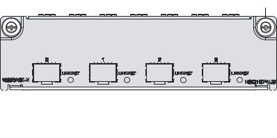
The NSQ1GP4U0 module is a high-speed Layer 3 Gigabit Ethernet interface module. The module provides four SFP optical interfaces that support the Layer-3 routing function. Each interface on the NSQ1GP4U0 module is available with an LED indicating its status. The NSQ1GP4U0 module is connected to the processor through a PCIE high-speed bus to provide all functions of a Layer-3 Ethernet interface with high performance.
Front view
Figure 2-4 NSQ1GP4U0 front view
|
|
|
|
|
|
|
|
|
|
|
|
|
|
|
|
|
|
|
|
|
|
|
|
|
|
|
|
|
|
|
|
|
|
|
|
|
|
|
|
|
|
|
|
|
|
|
|
|
|
|
|
(1) |
Captive screw |
|
|
|
|
(2) LINK/ACT LED |
||||||
(3) |
SFP interface |
|
|
|
|
|
|
|
|
|
||
LEDs
Table 2-3 Description of LEDs on the front panel of NSQ1GP4U0
|
|
LED |
|
Status |
Meaning |
|
|
LINK/ACT |
|
Off |
No link is present on the interface. |
|
|
|
|
|
|
|
|
|
On |
A 1000 Mbps link is present on the SFP interface. |
|
|
|
(Green) |
|
||
|
|
|
|
|
|
|
|
|
Blinking |
The SFP interface is transmitting or receiving data at 1000 Mbps. |
|
|
|
|
|
||
|
|
|
|
|
|
Interface specifications
Table 2-4 Interface specifications of NSQ1GP4U0
Item |
Specification |
|
Connector type |
SFP/LC |
|
|
|
|
Number of |
4 |
|
interfaces |
||
|
||
|
|
|
|
802.3, 802.3u, and 802.3ab |
|
Interface standards |
Ethernet_II |
|
|
Ethernet_SNAP |
|
|
|
|
Interface speed |
1000 Mbps |
|
|
|
2-4
|
Item |
|
|
|
Specification |
|
|
|
|
|
|
|
Multi-mode |
Single-mode |
Long haul |
Long haul |
Single-mode |
|
|
Type |
|
ultra-long |
||||
|
Optical |
|
short haul |
medium haul |
(1310 nm) |
(1550 nm) |
||
|
|
|
haul |
|||||
|
transmit |
|
|
|
|
|
|
|
|
|
|
|
|
|
|
|
|
|
power |
Min. |
|
–9.5 dBm |
–9 dBm |
–2 dBm |
–4 dBm |
–4 dBm |
|
|
|
|
|
|
|
|
|
|
|
Max. |
|
0 dBm |
–3 dBm |
5 dBm |
1 dBm |
2 dBm |
|
|
|
|
|
|
|
|
|
|
Receiving |
|
|
–17 dBm |
–20 dBm |
–23 dBm |
–21 dBm |
–22 dBm |
|
sensitivity |
|
|
|||||
|
|
|
|
|
|
|
|
|
|
|
|
|
|
|
|
|
|
|
Central wavelength |
|
850 nm |
1310 nm |
1310 nm |
1550 nm |
1550 nm |
|
|
|
|
|
|
|
|
|
|
|
Max. transmission |
|
0.55 km |
10 km (6.21 |
40 km (24.86 |
40 km (24.86 |
70 km (43.50 |
|
|
distance |
|
|
(0.34 miles) |
miles) |
miles) |
miles) |
miles) |
|
|
|
|
|
|
|
|
|
|
Fiber type |
|
|
62.5/125 μm |
9/125 μm |
9/125 μm |
9/125 μm |
9/125 μm |
|
|
|
multi-mode |
single-mode |
single-mode |
single-mode |
single-mode |
|
|
|
|
|
|||||
|
|
|
|
|
|
|
|
|
Interface cable
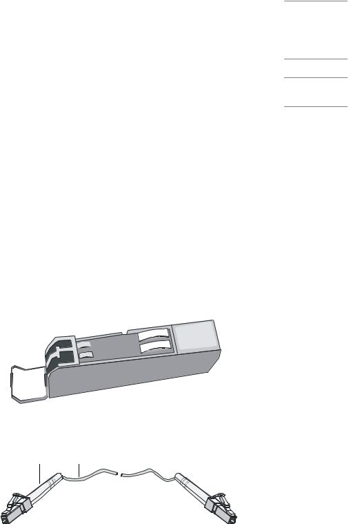
zThe NSQ1GP4U0 module can work with SFP optical transceivers using optical fibers with LC-type connectors.
Figure 2-5 and Figure 2-6 show an SFP optical transceiver and an optical fiber with LC-type connectors respectively.
Figure 2-5 SFP optical transceiver
Figure 2-6 Optical fiber with LC connectors
(1) LC-type connector |
(2) Optical fiber |
zThe NSQ1GP4U0 module can work with optical-to-electrical SFP modules using straight-through or crossover Ethernet cables. See Figure 2-2.
2-5
For how to connect the interface cable for the NSQ1GP4U0 module, refer to “Connecting an optical fiber or Ethernet cable to the NSQ1GP4U0 module" in Chapter 4 “Installing the U200 Series Device.”
NSQ1WLAN0 Module
Introduction
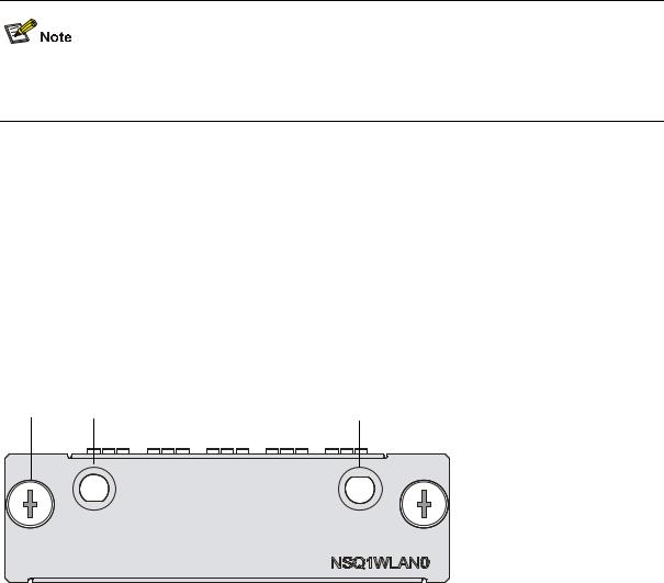
The NSQ1WLAN0 module is an 802.11a/b/g mini WLAN interface module that supports the Layer-3 routing function. The NSQ1WLAN0 module is connected to the processor through a 10-Gbps high-speed bus to provide all functions of a Layer-3 Ethernet interface with high performance.
Front view
Figure 2-7 NSQ1WLAN0 front view
(1) Captive screw |
(2) Auxiliary antenna interface |
(3) Main antenna interface |
|
Interface specifications
Table 2-5 Interface specifications of NSQ1GP4U0
|
|
Item |
|
Specification |
|
|
|
Interface type |
|
Antenna interface (2.4 GHz or 5 GHz) |
|
|
|
|
|
|
|
|
|
Number of interfaces |
1 |
|
|
|
|
|
|
|
|
|
|
Interface standards |
IEEE 802.11a, IEEE 802.11b, IEEE 802.11g |
||
|
|
|
|
|
|
|
|
|
|
6, 9, 12, 18, 24, 36, 48, 54 MHz |
802.11a |
|
|
Interface speed and negotiation |
|
|
|
|
|
|
1, 2, 5.5, 11 MHz |
802.11b |
|
|
|
mode |
|
||
|
|
|
|
|
|
|
|
|
|
6, 9, 12, 18, 24, 36, 48, 54 MHz |
802.11g |
|
|
|
|
|
|
Interface cable
The antenna interface of the NSQ1WLAN0 module supports 2.4 GHz and 5 GHz dual-frequency omni antennas.
2-6
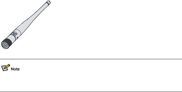
Figure 2-8 Omni antenna for the NSQ1WLAN0 module
For how to connect the antenna for the NSQ1WLAN0 module, refer to “Connecting an antenna for the NSQ1WLAN0 module” in Chapter 4 “Installing the U200 Series Device.”
Arranging Slots and Naming Interfaces
Slot Arrangement
The U200 series support interfaces such as console, AUX, Gigabit Ethernet, and WLAN interfaces. This section describes how these interfaces are numbered.
Naming Interfaces
The interfaces on a U200 series device are named following these conventions:
1)An interface is named in the form of interface-type X/Y, where
zinterface-type represents the type of the interface, such as GigabitEthernet.
zX represents the number of the slot in which the interface module is inserted.
zY represents the number of the interface on the interface module.
2)The interfaces on the same interface module uses the same slot number X.
3)The interfaces of the same type on an interface module are numbered starting with 0 for Y from left to right.
Examples
1)The five fixed GigabitEthernet interfaces on the U200-S are named as follows: z GigabitEthernet 0/0
z GigabitEthernet 0/1 z GigabitEthernet 0/2 z GigabitEthernet 0/3 z GigabitEthernet 0/4
2)If a 2GE module is installed on the U200-S, the GigabitEthernet interfaces on the 2GE module are
z
z
numbered as follows: GigabitEthernet 1/0 GigabitEthernet 1/1
2-7
Loading...